1.INTRODUCTION
1.1 PRECAUTIONS
1.2 TRANSPORT
1.3 PACKAGE CONTENT
1.4 USE
2. DEVICE CHARACTERISTICS
2.1 INTERNATIONAL PROTECTION DEGREE IP
2.2 CONSTRUCTION AND PRINCIPLE OF OPERATION
2.3 LCE COATING
2.4 DEVICE DIMENSIONS
2.5 DEVICE TECHNICAL DATA
3. ASSEMBLY
3.1 GENERAL PRINCIPLES
3.2 ROTATING MOUNTING BRACKET
4. INSTALLATION INSTRUCTIONS
4.1 CONNECTION OF THE DEVICE TO THE HYDAULIC SYSTEM
4.2 CONNECTION OF THE DEIVCE TO THE ELECTRICAL SYSTEM
5. PRECAUTIONS & WARNINGS
6. CONTROLS
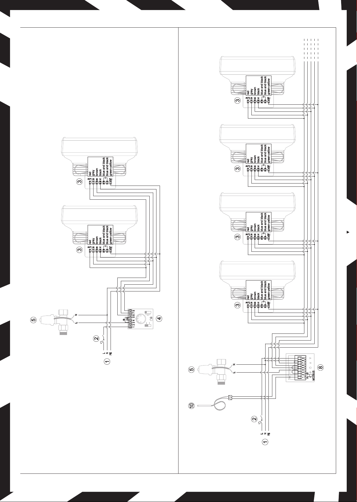
7. CONNECTION SCHEMES
8. TERMS OF WARRANTY
1. INTRODUCTION
Thank you very much for purchasing air water heater FARMER HCF. We would
like to congratulate you on excellent choice. Please read and keep this manual.
1.1 PRECAUTIONS
The buyer and the user of the air water heater Reventon Group brand should
read carefully the following instructions and proceed to the content
recommendations. Proceeding due to the following instruction guarantees
the correct usage and safety. In case of any doubts please contact directly
the producer Reventon Group sp. z o. o. [Ltd.]. The producer reserves the rights
to make changes to the technical documentation without previous notice.
Reventon Group sp. z o. o. [Ltd.] is not responsible for the damages which occur
due to improper installation, not keeping the device in repair or using the device
out of line. The installation should be carried out by the professional installers,
who possess the qualifications to install these types of devices. The installers
are responsible for making the installation as instructed in the technical data.
In case of unserviceable please plug out the device and contact
with the authorized for repair person or the supplier. During the installation,
use, service and periodical inspections all regulations and safety rules
must be followed.
1.2 TRANSPORT
During the acceptance of goods, it is needed to check the device to exclude
any damages. During the transport, it is needed to use the proper equipment,
it is necessary to carry the device by two people. In case of any damages please fill
in the damage report in presence of the supplier.
1.3 PACKAGE CONTENT
- heater
- operation and maintenance manual and warranty card
1.4 USE
Reventon Group Farmer HCF heating devices are designed for heating or cooling
surfaces in which aggressive conditions prevail, i.e. high content of acids,
ammonia and high concentration of dust. However, heaters should not be used in
highly corrosive environments for aluminum, copper and steel. The devices
should also not be installed in rooms where they would be exposed to the high
humidity or direct water action, exceeding the fan's resistance to water
penetration (see IP protection degree).
2. DEVICE CHARACTERISTICS
2.1INTERNATIONAL PROTECTION DEGREE IP
Determines the tightness of the electrical device (fan motor), which is defied
by two digits:
ź first characteristic digit - specifies protection of the device against access
to dangerous parts as well as against penetration of solids
ź second characteristic digit – determines the resistance of the engine
to the water ingress, its waterproofness
ENG
TECHNICAL DOCUMENTATON Fan motors of the Farmer HCF series have following IP:
5 - protection against access to hazardous parts by wire with a diameter of 1 mm
or more and against dust in quantities which might impair the proper functioning
of the equipment;
4 – protection against splashes of the water from any direction.
6- protection against access to hazardous parts by wire with a diameter of 1 mm
or more and against dust (total dust tightness);
5 – protection against stream of the water (12.5 l/min) from any direction
2.2 CONSTRUCTION AND PRINCIPLE OF OPERATION
Casing: made of expanded polypropylene (EPP). This material is characterized by
low density (light weighted) and high chemical and physical resistance.
It has an excellent sound and thermal insulation properties. Moreover, material
is environmentally friendly and "green", i.e. 100% recyclable.
Air stators: made of polypropylene PP. It is possible to adjust manually
the air stators to achieve the needed direction of the air flow. There are also
versions with confusor (increased airflow range) or with diffuser 360° (better
mixing of supplied and room air).
Heating coil: made of copper and aluminum. It is covered by LCE coating.
Supplied by distribution medium (heating or cooling), which circulates through
the coil and releases or extracts heat from the air. The coil has the following
technical parameters: the maximum temperature of the heating factor is 120°C;
maximum pressure 1.6 MPa; headers diameter ¾”. Farmer HCF series have
a double row heat exchanger.
Axial blowing fan IP54 (Farmer HCF IP54-3S): made of galvanized steel.
Fan has to ensure air flow through the exchanger. It has a single- and three phase
motor with the following parameters: protection degree IP54, rate current
0.7-1.08 A (depending on the operating mode). Diameter of the fan is 450 mm.
Axial blowing fan IP65 (Farmer HCF IP65): protective grid made of galvanized
steel, blades and casing made of plastic. Fan has to ensure air flow through
the exchanger. It has a single-, three phase motor with the following parameters:
protection degree IP65, rated current 2A. Diameter of the fan is 450 mm.
Rotating mounting bracket (optional equipment): enables the device
to be installed in several configurations (depending on the requirements)
and the unit to be rotated in a horizontal plane.
Farmer HCF IP54-3S
Farmer HCF IP65
2.3 LCE COATING
The coating technology is based on immersion of the exchanger in the liquid LCE,
which allows ptotection of the whole surface of the exchanger. The LCE coating
is waterproof and protects the heater exchanger from corrosion, mould
and bacteria without compromising heat transfer efficiency. It is flexible enough
not to be teared during thermal expansion of metal parts.
Periodic maintenance guarantees the resistance of the LCE coating
to the following concentrations of chemical factors:
In addition the above LCE COATING demonstrates high resistance to fumes
of the following: Lactic Acid, Oxalic Acid, Humic Acid, Saltwater and NOx.
Agent Concentration
Hydrochloric Acid 30%
Sulphuric Acid 30%
Phosphoric Acid 50%
Acetic Acid 10%
Sodium Hydroxide 10%
Ammonia in the air 30 ppm
Urea in the air 30 ppm
Trichloroethylene 30 ppm
Toluene 25 ppm
Methylated Spirits
30 ppm
Mineral Turps 30 ppm
MEK 25 ppm
Acetone 25 ppm
Hydrogen Sulphide
30 ppm


 Operation and maintenance instructions")