Reverso Outboard Flushing System 1.5 User manual

Manual
Automatic Outboard Flushing System 1.5
Shown: Version 1.5 B with optional remote switch kit and optional inlet hose kit.

This page intentionally left blank.

Table of Contents
System Overview............................................................................... 4
Technical Specications, Electrical, and Installation.......................... 5
Inlet Hose Kit ..................................................................................... 6
Remote Switch Kit ............................................................................. 7
Installation Diagram: 2 Engine Setup ................................................ 8
Installation Diagram: 3 Engine Setup ................................................ 9
Installation Diagram: 4 Engine Setup .............................................. 10
Installation Diagram: 5 Engine Setup .............................................. 11
Version A Dimensions: 2 Engine Setup ........................................... 12
Version A Dimensions: 3 Engine Setup ........................................... 13
Version A Dimensions: 4 Engine Setup ........................................... 14
Version B Dimensions: 2 Engine Setup........................................... 15
Version B Dimensions: 3 Engine Setup........................................... 16
Version B Dimensions: 4 Engine Setup........................................... 17
Version B Dimensions: 5 Engine Setup........................................... 18
Operation and Troubleshooting ....................................................... 19

4
System Overview
Power input
Version A: Delphi connector for optional remote switch
Version B: Deutsch connector for optional remote switch
Cover
Start button and LED status indicator
Base
3/4” hose barb - water inlet
3/8” or 1/2” hose barb - water outlet to engine
Inlet hose kit (optional and available in various hose lengths)
Remote switch kit (optional and available in various cable lengths)
7
1
2A
5
3
6
4
1
3
4
5
6
7
8
9
2B
8
9
2B
2A
5
Technical Specications, Electrical, and Installation
Basic Features
• 12or24Volt
• 2,3,or4Enginesetup
• StartbuttonwithLEDstatusindicator
• 3’inlethosekitincluded
Optional Features
• RemoteSwitchKitwithLEDstatusindicator.Availablein
lengthsof3,6,9,12,15and18feet
• InletHoseKit.Availableinhoselengthsof1,2,3,6,and
9feet
Primary Inspection
• Upondeliveryinspectthesystemforanydamagethat
mayhaveoccurredduringshipment.
• Iftheunitisdamagedupondelivery,contactthe
shippingcompanyimmediately.
Mounting
• Mountingholes:Ø3/16”
• Orientation:Anydirectionon
aatsurfaceofthebulkhead
oraccessoriescompartment,
exceptupsidedown.
Electrical
• Installationmustincludeprotectionwith5Afuseor
breaker(providedbyinstaller).
• ONLY CONNECT BLACK (-) AND RED (+) WIRES
TO SAME RESPECTIVE COLOR. DAMAGE CAN
OCCUR TO THE SYSTEM IF THE WIRES ARE
CROSSED.
• Installationofunitshouldonlybeperformedby
qualiedelectricianwhohavethoroughlyreadand
understandstheinstallationinstructionscoveredin
thismanualandadheretoABYCrequirements.
• Toavoidtheriskofharmorinjury,makesurethat
thepowersupplyisdisconnected.Ensurethat
thepowersupplyisatzerovoltswithamultimeter
beforemakinganyelectricalconnections.
• Besurethatthepowersourceavailablematches
thepowerrequirements.
Connection to Engines
Hose:Smallerthantherequireddiameterhoseis
notrecommended.Choosettingswhichtthe
appropriatehosesize.Thehosewillrunfromthe
system,throughtheoutboardloom,andtotheengine.
Locatetheushingportontheengine,splittheline,
andconnectthehose.Or,choosetoinstallatee.
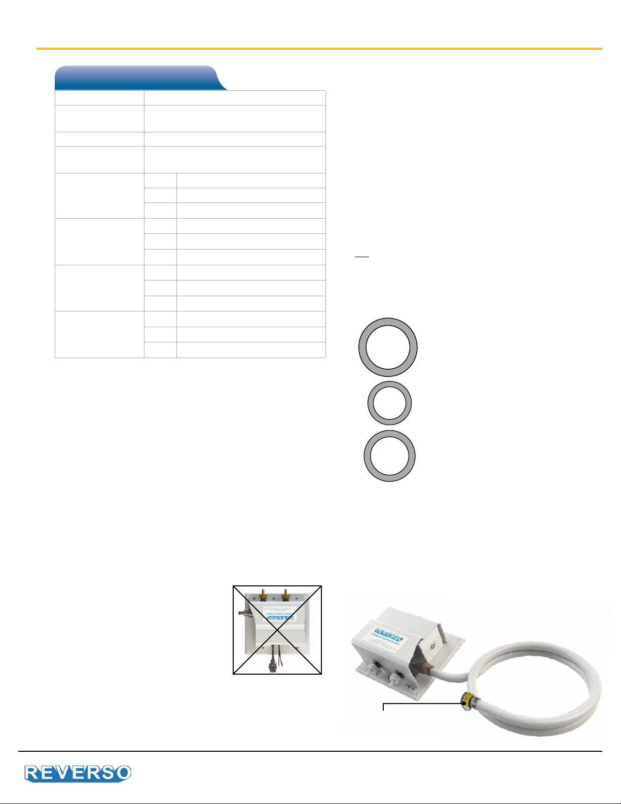
Important: Sealed Water Inlet
Incorporateasealedcapforthewaterinlettoblock
anybackow.Chooseoneofthefollowingways:
• InstalltheInletHoseKitwhichincludesacapon
thehoseendalready(shownbelow).
• IftheInletHoseKitisnotused,analternativecan
beabulkheadcap,quickdisconnect,orother
sealedttingprovidedbytheinstaller.
Technical Specications
Voltage 12V or 24V
Max. Amp. Draw 3A / 12V
1.5A / 24V
Water Inlet Hose 3/4”
Water Outlet
To Engine
3/8” hose barb, or 1/2” hose barb for
engines over 300HP
Dimensions
2 Engine Setup
A 10.5” / 267 mm
B 10” / 254 mm
C 4.7” / 119 mm
Dimensions
3 Engine Setup
A 14.17” / 360 mm
B 10” / 267 mm
C 4.7” / 119 mm
Dimensions
4 Engine Setup
A 17.84” / 453 mm
B 10” / 267 mm
C 4.7” / 119 mm
Dimensions
5 Engine Setup
A 21.5” / 546 mm
B 10” / 267 mm
C 4.7” / 119 mm 3/4” ID
3/8” ID
1/2” ID
3/8” inner diameter hose is required
for water outlet (to engines).
Reinforced hose is recommended.
On the version designed for
engines over 300HP, 1/2” inner
diameter hose is required for water
outlet (to engines). Reinforced
hose is recommended.
3/4” inner diameter hose is required
for water inlet.
Capped tting on the
Inlet Hose Kit
6
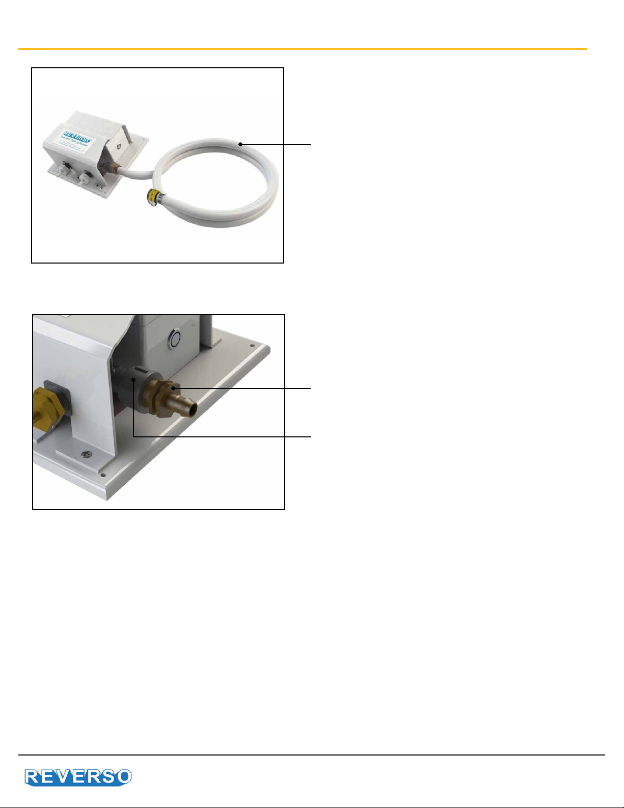
Inlet Hose Kit
Inlet Hose Kit Installation
When installing the inlet hose kit, do not turn water inlet
hose barb. Only turn the collar of the valve to prevent
damage to the o-ring seal.
Water Inlet hose barb
Collar of the valve
Availableinhoselengthsof1,2,3,6,and9feet

7
Remote Switch Kit
Remote Switch Kit Version B
Remote Switch Kit Version A
Version B is equipped with Deutsch connector. Remove dust cover and connect remote switch kit.
Version A is equipped with Delphi connector. Connect remote switch kit.
Availableinwirelengths3,6,9,12,15and18feet
8
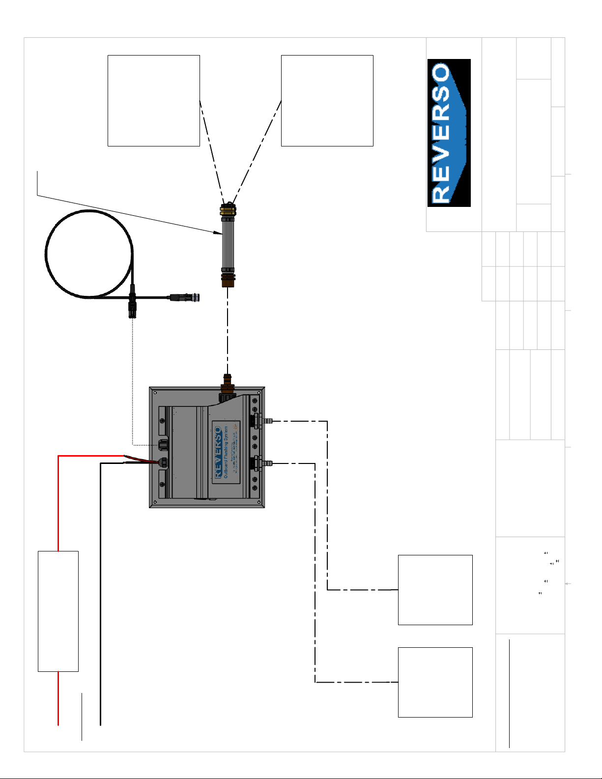
2
2
Power In
Red (Postive)
If Inlet Hose Kit is not used.
Installer must
supply
a Cap
or Quick-disconnect on hose
running from unit to the
water inlet.
Outboard
Engine 2
Flush Port
Outboard
Engine 1
Flush Port
5 Amp Fuse
or Circuit Breaker
(NOT Included with Unit)
Garden
Hose
Separate Fresh
Water Inlet
Fitting on Boat.
1 Foot long Inlet
Hose Kit Included
(Optional Longer
Inlet Hose Kit)
Optional
Remote Switch
and Harness
Black (Negative)
A
DO NOT SCALE DRAWING
OFS V1.0 Application-0616
SHEET 1 OF 4
6/7/2016
JC
UNLESS OTHERWISE SPECIFIED:
SCALE: 1:6
WEIGHT:
REV
DWG. NO.
A
SIZE
TITLE:
NAME
DATE
COMMENTS:
Q.A.
MFG APPR.
ENG APPR.
CHECKED
DRAWN
FINISH
MATERIAL
INTERPRET GEOMETRIC
TOLERANCING PER:
DIMENSIONS ARE IN INCHES
TOLERANCES:
FRACTIONAL
1/64
ANGULAR: MACH
BEND
0.2
TWO PLACE DECIMAL
.01
THREE PLACE DECIMAL
.005
PROPRIETARY AND CONFIDENTIAL
THE INFORMATION CONTAINED IN THIS
DRAWING IS THE SOLE PROPERTY OF
REVERSO PUMPS
ANY REPRODUCTION IN PART OR
AS A WHOLE WITHOUT THE WRITTEN
PERMISSION OF
REVERSO PUMPS
IS PROHIBITED.
5
4
3
2
1
OFS-2-12
Install Application
JC
5/11/2016
Installation Diagram: 2 Engine Setup

9
3
2
Power In
Red (Postive)
If Inlet Hose Kit is not used.
Installer must
supply
a Cap
or Quick-disconnect on hose
running from unit to the
water inlet.
Outboard
Engine 3
Flush Port
Outboard
Engine 2
Flush Port
Outboard
Engine 1
Flush Port
5 Amp Fuse
or Circuit Breaker
(NOT Included with Unit)
Garden
Hose
Separate Fresh
Water Inlet
Fitting on Boat.
1 Foot long Inlet
Hose Kit Included
(Optional Longer
Inlet Hose Kit)
Optional
Remote Switch
and Harness
Black (Negative)
A
DO NOT SCALE DRAWING
OFS V1.0 Application-0616
SHEET 2 OF 4
6/7/2016
JC
UNLESS OTHERWISE SPECIFIED:
SCALE: 1:6
WEIGHT:
REV
DWG. NO.
A
SIZE
TITLE:
NAME
DATE
COMMENTS:
Q.A.
MFG APPR.
ENG APPR.
CHECKED
DRAWN
FINISH
MATERIAL
INTERPRET GEOMETRIC
TOLERANCING PER:
DIMENSIONS ARE IN INCHES
TOLERANCES:
FRACTIONAL
1/64
ANGULAR: MACH
BEND
0.2
TWO PLACE DECIMAL
.01
THREE PLACE DECIMAL
.005
PROPRIETARY AND CONFIDENTIAL
THE INFORMATION CONTAINED IN THIS
DRAWING IS THE SOLE PROPERTY OF
REVERSO PUMPS
ANY REPRODUCTION IN PART OR
AS A WHOLE WITHOUT THE WRITTEN
PERMISSION OF
REVERSO PUMPS
IS PROHIBITED.
5
4
3
2
1
OFS-3-12
Install Application
JC
5/11/2016
Installation Diagram: 3 Engine Setup

10
4
2
Power In
Red (Postive)
If Inlet Hose Kit is not used.
Installer must
supply
a Cap
or Quick-disconnect on hose
running from unit to the
water inlet.
Outboard
Engine 4
Flush Port
Outboard
Engine 3
Flush Port
Outboard
Engine 2
Flush Port
Outboard
Engine 1
Flush Port
5 Amp Fuse
or Circuit Breaker
(NOT Included with Unit)
Garden
Hose
Separate Fresh
Water Inlet
Fitting on Boat.
1 Foot long Inlet
Hose Kit Included
(Optional Longer
Inlet Hose Kit)
Optional
Remote Switch
and Harness
Black (Negative)
A
DO NOT SCALE DRAWING
OFS V1.0 Application-0616
SHEET 3 OF 4
6/7/2016
JC
UNLESS OTHERWISE SPECIFIED:
SCALE: 1:6
WEIGHT:
REV
DWG. NO.
A
SIZE
TITLE:
NAME
DATE
COMMENTS:
Q.A.
MFG APPR.
ENG APPR.
CHECKED
DRAWN
FINISH
MATERIAL
INTERPRET GEOMETRIC
TOLERANCING PER:
DIMENSIONS ARE IN INCHES
TOLERANCES:
FRACTIONAL
1/64
ANGULAR: MACH
BEND
0.2
TWO PLACE DECIMAL
.01
THREE PLACE DECIMAL
.005
PROPRIETARY AND CONFIDENTIAL
THE INFORMATION CONTAINED IN THIS
DRAWING IS THE SOLE PROPERTY OF
REVERSO PUMPS
ANY REPRODUCTION IN PART OR
AS A WHOLE WITHOUT THE WRITTEN
PERMISSION OF
REVERSO PUMPS
IS PROHIBITED.
5
4
3
2
1
OFS-4-12
Install Application
JC
5/11/2016
Installation Diagram: 4 Engine Setup
Table of contents
Popular Boating Equipment manuals by other brands


Humphree
Humphree HCS-5 installation manual

Vetus
Vetus BOW4512D Operation manual and installation instructions

Dock Doctors
Dock Doctors SLIDING BOARDING STEP Assembly instructions

Mastervolt
Mastervolt Mass Combi 12/2000-100 Quick installation

SeaView
SeaView PM5-FMD-8 installation instructions

Hobie
Hobie Mirage 360 manual


