Revo PJL3211 User manual

Pro
Video
Stabilizer
ST-1000

2
Thank you for choosing Revo and congratulations on your purchase of the Revo ST-1000 Pro Video
Stabilizer. The Revo Pro Video Stabilizer is a compact, lightweight camera stabilization rig that uses
counterbalance weights and a gimbal to help you keep your camera steady when shooting video—
eliminating distracting camera movement for smoother, more professional-looking movies.
The ST-1000 can support a DSLR or camcorder weighing up to 4.85 pounds. A comfortable
padded hand grip supports the camera mount. The universal camera mount is adjustable and has a
quick-release mount. A super-smooth gimbal and adjustable counterweight help keep the camera
balanced and stable. You can use the built-in bubble level to check the camera’s balance at any time.

3
Components
Grip Handle
Grip Handle
Thumb
Stabilizer
Thumb
Stabilizer
Gimbal
Gimbal
Fore/Aft Trim Screw Fore/Aft
Trim Screw
Lock Screw
Lock Screw
Lock Screw
Camera
Plate
Lock
Lock Screw
Side to Side Trim Screw
Horizontal/Vertical
Adjustment
Camera Mounting Plate
Camera Mounting Screw
Counterbalance Weights

4
Warnings
• Please read and follow these instructions, and keep this manual in
a safe place.
• Handle the unit with care.
• Clean the unit with a soft, dry cloth.
• Use only parts provided by the manufacturer.
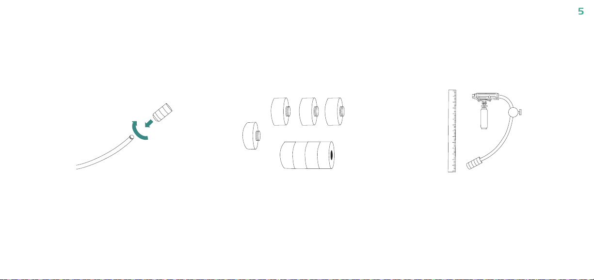
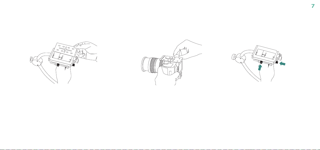
• Make sure everything is secure before proceeding.
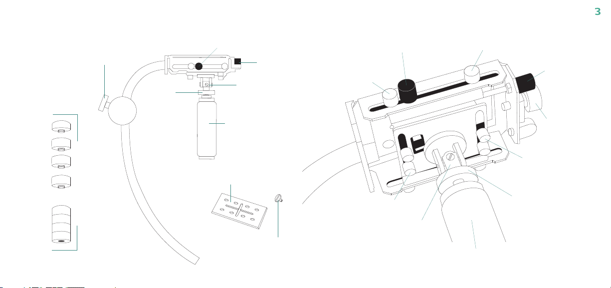
• Make sure the item is intact and that there are no missing parts.
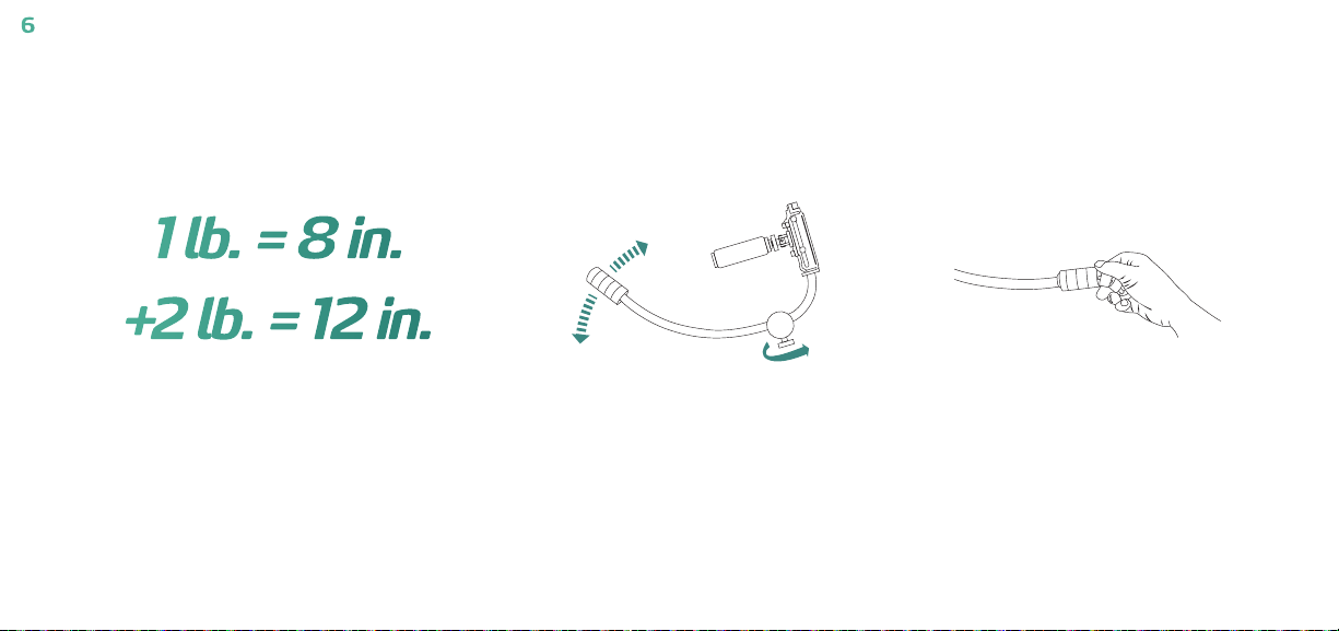
• Do not exceed the maximum load capacity.
• All photos are for illustrative purposes only.
Limited One-year Warranty
Revo provides a limited warranty that this product is free from defects in materials and workmanship to the original purchaser under normal use for a period of one (1) year from the
original purchase date or thirty (30) days after replacement (the “Warranty Period”), whichever occurs later. Our responsibility with respect to this limited warranty shall be limited
solely to repair or replacement, at its option, of any product which fails during normal consumer use.
To obtain warranty coverage during the Warranty Period, contact your place of purchase (“Seller”) to obtain a return merchandise authorization (“RMA”) number, and return to Seller
the defective product along with proof of purchase and the RMA number.
This warranty does not extend to damage or failure which results from misuse, neglect, accident, alteration, abuse, improper installation or maintenance. EXCEPT AS PROVIDED
HEREIN, REVO MAKES NEITHER ANY EXPRESS WARRANTIES NOR ANY IMPLIED WARRANTIES, INCLUDING BUT NOT LIMITED TO ANY IMPLIED WARRANTY OF
MERCHANTABILITY OR FITNESS FOR A PARTICULAR PURPOSE. This warranty provides you with specific legal rights, and you may also have additional rights which vary from
state to state.
© Copyright 2012 Gradus Group www.RevoCinema.com

5
The ST-1000 Pro Video Stabilizer uses a gimbal device with a grip to keep the camera steady. The camera mount “floats,” anchored by the counterbalance
weight at the end of the micro-adjustable counterbalance. Setting up this mechanism for the best results requires time and patience. Once it has been set-
up properly, the settings can be recorded and used quickly without further set-up required. Always be sure to keep one hand on your camera when making
adjustments, to prevent the camera from falling. Keep in mind that any professional technology requires practice and patience to master, with your results
directly related to the time you devote to it.
1 lb. = 8 in.
+2 lb. = 12 in.
1 lb. = 8 in.
+2 lb. = 12 in.
1 lb. = 8 in.
+2 lb. = 12 in.
1Attach the largest counter balance weight
to the end of the counter balance extension.
(After mounting the camera, smaller
counterbalance weights may be added, if
necessary.). It doesn’t need to be overly
tightened — just tight enough so that there’s
no play in the screw.
2For the starting position, measure the counter
balance hinge distance from the end of the
weight on the hinge to the end of the camera
mounting base.
Pre-Adjusting the Counterbalance Hinge
Note: There are five weights included with this
stabilizer—one large weight and four small weights.
You can use any one of these weights (including
just a single small weight), or any combination
of weights (including all of the weights) on the
counterbalance extension to achieve the correct
counterbalance for your camera.

6
1 lb. = 8 in.
+2 lb. = 12 in.
1 lb. = 8 in.
+2 lb. = 12 in.
4You can adjust the vertical balance by turning
the horizontal and vertical trim screw to open
or close the counterbalance hinge.
5Adding or subtracting counterbalance weight
will also affect the balance. The correct
balance should be slightly bottom-heavy.
1 lb. = 8 in.
+2 lb. = 12 in.
3If your camera weighs approximately one
pound (450 g), set the counter balance
hinge distance to about 8 inches (23 cm).
If your camera weighs two pounds or more,
set the counter balance hinge distance to
approximately 12 inches (30.48 cm).

7
Mounting the camera
1 lb. = 8 in.
+2 lb. = 12 in.
1 lb. = 8 in.
+2 lb. = 12 in.
1Remove the quick-release camera plate from
the receiver mount. 3Check that the side-to-side trim screw and
the fore-and-aft trim screw on the receiver
mount are at their respective start points—the
long screw controlled by the black knob on
the mounting platform, in each case, should
not extend past the sheath at the end of the
screw.
1 lb. = 8 in.
+2 lb. = 12 in.
2Using the included 1/4″mounting screw,
attach the camera to the quick-release plate,
and securely tighten the screw.

8
1 lb. = 8 in.
+2 lb. = 12 in.
1 lb. = 8 in.
+2 lb. = 12 in.
4Remove the quick-release camera plate from
the receiver mount. 5Check that the side-to-side trim screw and
the fore-and-aft trim screw on the receiver
mount are at their respective start points—the
long screw controlled by the black knob on
the mounting platform, in each case, should
not extend past the sheath at the end of the
screw.
Note: The distance of the weight from the
camera affects the balance, and can be
adjusted using the horizontal and vertical
trim screw to open or close the arc of the
counterbalance hinge.
Note: When mounting a DSLR camera with a heavy lens attached (such as a telephoto or zoom lens), move the plate forward in the direction of the lens as a
starting point. When mounting a video camcorder, mount the plate so that it’s centered or slightly forward of the center of the camera as a starting point.
For purposes of balance, you can use any of the holes on the mounting plate for mounting the camera, in addition to the X slot.
1 lb. = 8 in.
+2 lb. = 12 in.

9
1Gripping the handle with your camera
mounted on the mounting platform, hold it up
to see if it tilts to the left or to the right
2To make adjustments to the side-to-side placement of the camera, loosen the four silver screws
on the bottom of the camera mount and use the black screw on the side of the mounting platform
to adjust the side-by-side position of the camera. When you’ve achieved the best possible side-
to-side balance, tighten the four silver screws on the bottom of the mount securely.
Adjusting Horizontal and Vertical Trim
1 lb. = 8 in.
+2 lb. = 12 in.
1 lb. = 8 in.
+2 lb. = 12 in.

10
1 lb. = 8 in.
+2 lb. = 12 in.
1 lb. = 8 in.
+2 lb. = 12 in.
1 lb. = 8 in.
+2 lb. = 12 in.
3If the camera dips forward or backwards, you
can make adjustments to the front-to-back
position of the camera.
4Loosen the two silver screws on the left side
and the two silver screws on the right side of
the mounting platform, then use the black
screw at the back of the platform to move the
camera forward or backward.
5When you’re finished, tighten the two silver
screws on the right side of the platform and
the two silver screws on the left side of the
platform.

11
1 lb. = 8 in.
+2 lb. = 12 in.
6You may need to repeat each of these steps several times to achieve the
correct balance. When you have the correct balance, note the weight
you used, the distance that the counter balance hinge is open, and the
position of the quick-release plate on the mounting platform. Then, you
can easily use the same settings for every shoot.
Note: Once you’ve achieved optimal balance of your camera on the ST-
1000, you will be able to pan or tilt the camera while shooting. To pan
the camera, place the thumb of the hand supporting the ST-1000 on the
control ring directly above the hand grip and below the receiver mount.
Using your thumb, the knurled ring can be carefully turned to the left or
to the right to pan the camera. To tilt the camera, put your thumb firmly
against the bottom of the receiver mount between the two silver screws
at the back of the receiver mount and the knurled ring attached to the
bottom of the receiver mount. Apply pressure carefully to tilt the camera
as desired.
When you’re finished shooting, remove the camera and quick-release
plate from the stabilizer. If the stabilizer is placed on a flat surface with
the camera mounted, it could possibly cause stress or damage to the
camera.

12
Operating the ST-1000 with two hands provides the best control of your
camera. Using one hand is less precise than using two, but it can be very
useful for shots high over your head, shooting off to one side, or moving
through a crowd.
For a two-handed grip, (see Fig. 1) take the grip in one hand and support
the weight of the camera. This hand carries the ST-1000 with your
camera attached, avoiding contact with anything that could disrupt the
smooth flow of your shot. The supporting hand doesn’t pan or tilt the
camera or do anything other than support it as firmly as possible. With
the thumb and two fingertips of your other hand, touch the control ring
lightly when you want to change where the camera is pointing.
Move the knurled ring to pan, and press the bottom of the receiver
mount to tilt the camera. If possible, don’t let this operating hand touch
the supporting hand, unless you need two hands to support the weight of
your camera. You can slide the little finger of the operating hand between
the fingers of supporting hand to help support the weight in that case,
while keeping a light touch on the control ring.
If you’re using one hand to support the ST-1000, (see Fig. 2) place your
hand on the grip, so that your second finger is just below the control ring.
Use your second, third, and pinky finger to firmly hold the grip. Wrap your
index finger around the base of the receiver mount and your thumb on
the control ring. You can use your arm as a crank when you pan, while
you use your thumb to pan or tilt the camera, using the control ring.
Visit RevoCinema.com for more information on our complete line
of video mounting products.
Holding the ST-1000

13
Fig. 1 Fig. 2

14
______________________________________________________________________
______________________________________________________________________
______________________________________________________________________
______________________________________________________________________
______________________________________________________________________
______________________________________________________________________
______________________________________________________________________
______________________________________________________________________
______________________________________________________________________
______________________________________________________________________
______________________________________________________________________
______________________________________________________________________
______________________________________________________________________
______________________________________________________________________
______________________________________________________________________
______________________________________________________________________
______________________________________________________________________
______________________________________________________________________
______________________________________________________________________
______________________________________________________________________
______________________________________________________________________
______________________________________________________________________
______________________________________________________________________
______________________________________________________________________
______________________________________________________________________
______________________________________________________________________
______________________________________________________________________
______________________________________________________________________
______________________________________________________________________
______________________________________________________________________
______________________________________________________________________
______________________________________________________________________
______________________________________________________________________
______________________________________________________________________
______________________________________________________________________
______________________________________________________________________
______________________________________________________________________
______________________________________________________________________
Notes

15
______________________________________________________________________
______________________________________________________________________
______________________________________________________________________
______________________________________________________________________
______________________________________________________________________
______________________________________________________________________
______________________________________________________________________
______________________________________________________________________
______________________________________________________________________
______________________________________________________________________
______________________________________________________________________
______________________________________________________________________
______________________________________________________________________
______________________________________________________________________
______________________________________________________________________
______________________________________________________________________
______________________________________________________________________
______________________________________________________________________
______________________________________________________________________
______________________________________________________________________
______________________________________________________________________
______________________________________________________________________
______________________________________________________________________
______________________________________________________________________
______________________________________________________________________
______________________________________________________________________
______________________________________________________________________
______________________________________________________________________
______________________________________________________________________
______________________________________________________________________
______________________________________________________________________
______________________________________________________________________
______________________________________________________________________
______________________________________________________________________
______________________________________________________________________
______________________________________________________________________
______________________________________________________________________
______________________________________________________________________

© Copyright 2012 Gradus Group
www.RevoCinema.com
Table of contents
Other Revo Camera Accessories manuals