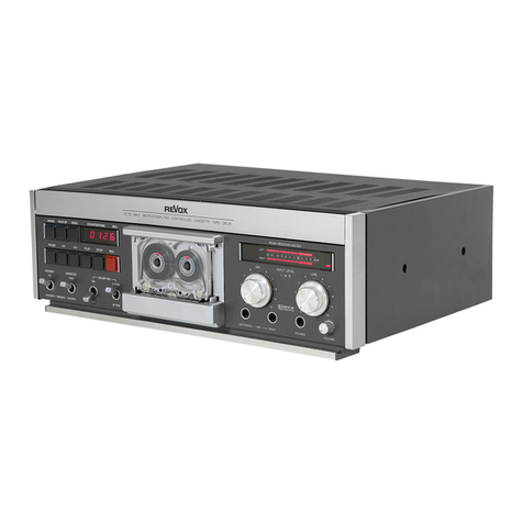
Revox C270 User manual

ienungsanleitung
Operating
Instructions
xe)
i)
ian)
Mode
d'emploi
7
RESE
ARCH.
SE

Operating
Instructions
REVOX
C270
-
Tape
Recorder
SECTION
1
SECTION
2
SECTION
3
SECTION
4
SECTION
5
For
the
sake
of
clarity
and
ease
of
use,
these
operating
instructions
have
been
subdivided
into
the
following
five
Sections:
Installation
and
first
time
operation
Contains
all
information
required
for
correct
installation
and
con-
nection
of
the
tape
recorder.
Operation
Provides
basic
information
concerming
the
operation
of
the
tape
recorder
such
as
PLAY
and
RECORD
mode.
Extended
Operation
Explains
all
auxiliary
and
special
functions
that
are
not
described
in
Section
2
such
as
LOCATOR,
waste
basket
mode,
and
editing.
Technical
appendix
Contains
interesting
information
on
the
design
of
reel-to-reel
tape
recorders,
hints
on
level
standards,
as
well
as
for
converting
the
a
The
technical
data
and
dimensions
are
also
included
in
this
ection.
List
of
keypad
functions
Contains
quick-reference
instructions
for
the
experienced
user
and
provides
a
quick
overview
of
all
keypad
functions.
Indexed
synoptical
drawing
Atthe
end
of
this
manual
you
will
find
a
foldout
page
with
a
synop-
tical
drawing
on
which
index
numbers
have
been
provided.
The
index
numbers
which
in
the
text
appear
between
brackets
corre-
spond
to
those
on
the
drawing.

ma
a
eg
WARRANTY
PACKING
MATERIAL
Protect
your
tape
recorder
from
exposure
to
excessive
heat
and
moisture.
Install
it
in
a
position
where
the
ventilation
louvers
are
not
obstructed.
A
special
warranty
request
card
is
included
with
all
equipment
sold
within
the
Federal
Republic
of
Germany.
This
card
is
located
either
inside
the
packing
or
ina
plastic
pouch
attached
to
the
out-
side
of
the
packing.
Should
this
card
be
missing,
please
consult
your
REVOX
dealer
or
your
national
REVOX
distributor.
Warranty
cards
for
equipment
sold
in
Switzerland
or
Austria
are
issued
directly
by
the
authorized
dealer.
.
Please
note
that
the
warranty
is
only
valid
within
the
country
in
which
the
equipment
has
been
sold.
The
warranty
becomes
null
and
void
if
unauthorized
modifications
or
unprofessional
repairs
are
made.
Please
retain
the
original
box
for
reuse
in
case
your
equipment
ever
needs
to
be
transported.
The
packing
material
has
been
especially
designed
to
protect
your
valuable
equipment
from
me-
chanical
shock
in
transit.
,

Contents
SECTION
1
Installation
and
first
operation
SECTION
2
Operation
SECTION
3
Extended
operation
SECTION
4
Technical
appendix
SECTION
5
Items
included
with
the
recorder
Setup
Line
Voltage
Connecting
the
signal
sources
Switching
on
the
tape
recorder
Inserting
the
tape
Tape
speed
(SLOW/FAST)
Tape
transport
functions
PLAY
mode
RECORD
mode
Monitor
speaker
Variable
tape
speed
Locator
function
LOOP
mode
Waste
basket
mode
(T-DUMP)
Editing
function
(EDIT)
Tape
scissors
Reproduce
delay
Automatic
recording
Track
configuration
on
the
tape
Care
and
maintenance
instructions
Equalizations
(IEC,
NAB)
—_
W-OOON
Alternate
tape
speeds
Calibration
(standard
level)
Technical
data
Dimensions
Quick-reference
descriptions
Index
of
keypad
functions
Correct
insertion
of
the
tape
Indexed
synoptical
diagram
Audio
block
diagram

SECTION
1
.
Items
included
with
the
recorder,
Installation
Setup
in
addition
to
these
operating
instructions
and
the
tape
recorder,
the
packing
also
contains
a
power
cord
fitted
with
a
plug
that
conforms
to
the
standards
of
your
country,
as
well
as
3
plugs
and
a
set
of
7
fuses
for
MONITOR,
FADER
START,
RS282,
plus
a
set
of
diagrams.
Please
consult
your
dealer
if
any
of
the
above
items
is
missing
or
incorrect.
These
operating
instructions
are
also
avail-
able
in
the
following
languages:
ltems
included
with
the
recorder
DEUTSCH:
Bestellnummer:
10.30.0780
FRANCAIS:
No.
comm.:
10.30.0790
Install
your
recorder
in
a
position
where
the
ventilation
louvers
are
not
obstructed.
A
venti-
lation
clearance
of
at
least
10
mm
(1%2”)
should
be
maintained
to
other
equipment,
walls
and
furnishings.
Setup
Important
safety
instructions
Connectthe
recorder
to
an
AC
outlet
using
the
:
included
power
cable.
Always
keep
the
equipmentin
dry
condition.
It
is
extremely
hazardous
to
operate
it
in
wet
a
(bathroom,
laundry
room,
basement,
etc.).
The
recorder
is
designed
to
be
operated
in
any
position
between
horizontal
and
vertical.
In
case
of
a
malfunction
or
a
defect,
immedia-
tely
disconnect
the
power
plug
and
have
the
tape
recorder
inspected
by
an
authorized
REVOX
dealer.

Installation
Setup
Make
sure
that
the
voltage
rating
visible
through
the
window
agrees
with
the
local
AC
supply
voltage.
If
necessary,
the
unit
can
be
converted
to
a
dif-
ferent
line
voltage
but
this
work
should
be
per-
es
formed
by
your
dealer.
Checking
the
line
voltage
The
LINE
INPUT
CH1
and
LINE
INPUT
CH2
should
be
connected
to
the
OUTPUT
connec-
tors
of
a
signal
source
(mixing
console).
For
this
purpose
you
can
use
commercially
available,
balanced
connecting
cables
or
you
can
prepare
the
cables
yourself.
Make
sure
that
the
conductors
are
wired
correctly.
Connecting
the
signal
sources
WMa=—==
6
OOe
eH
We—==——==
-
OF
#¥
oS
M————
-
OC
&€6@
Wi
°
OF
ERE
WM
>
OG
CECE
C279
The
LINE
OUTPUT
CH1
and
LINE
OUTPUT
CH
2
should
be
connected
to
the
INPUT
con-
nectors
of
your
amplifier
or
to
the
inputs
of
a
mixing
console.
For
this
purpose
you
can
use
commercially
available,
balanced
connecting
cables
or
you
can
prepare
the
cables
yourself.
Mig
sure
that
the
conductors
are
wired
cor-
rectly.
Connecting
the
outputs
Ose
eo@
°Oseece
°OGeene
OO
eeoe
Duets
a
sce
Ma
00
G
ad
oe
ied
Wi
0
R=
-
Oo
eece
im
——
mm
m—
——
C279

Installation
Setup
Switching
on
the
tape
recorder
SEL
STEP
TRANS
SEARCH
RESET
When
you
press
the
POWER
[1]
key
on
the
front
panel,
the
tape
recorder
switches
on.
Press
the
same
key
again
and
it
switches
off.
When
you
switch
on
the
tape
recorder,
the
VU-meters
are
illuminated
and
the
last
active
system
parameters
(tape
speed,
tape
add-
ress)
are
shown
on
the
real-time
tape
counter
[7],
and
the
output
selectors
(INPUT,
SYNC,
READY)
are
restored
to
their
previous
posi-
tion.
The
last
active
settings
are
stored
again
when
the
unit
is
switched
off.
The
tape
recorder
cannot
be
switched
on
or
off
by
means
of
the
remote
control.
After
the
tape
recorder
has
been
switched
on,
the
Real
Time
counter
[7]
displays
the
chosen
tape
speed
“ips”
for
approx.
2
seconds.
Sub-
sequently,
the
actual
tape
position
is
shown.

SECTION
2
Operation
Inserting
the
tape
Three-pronged
reel
(DIN)
NAB
reel
AEG
platter
,
(for
self-supporting
pancakes)
Threading
the
tape
Mount
the
full
reel
on
the
left-hand
spindle
[2]
and
the
empty
reel
on
the
right-hand
spindle
[3].
To
lock
the
reel,
pull
out
the
three-pronged
guide
and
rotate
it
by
60°.
Mount
the
NAB
adapters
on
the
spindles
[2/3].
To
lock
the
adapter,
pull
out
the
three-
pronged
guide
and
rotate
it
by
60°.
Mount
the
full
NAB
tape
reel
on
the
left-hand
NAB
adap-
ter
and
the
empty
NAB
reel
on
the
right-hand
NAB
adapter.
To
secure
the
reels,
turn
the
up-
per
part
of
the
adapter
clockwise
until
it
en-
gages.
Mount
the
adapter
platters
on
the
spindles
[2/3].
To
lock
the
adapter,
pull
out
the
three-
pronged
guide
and
rotate
it
by
60°.
Mount
the
tape
pancake
on
the
left-hand
platter
and
an
empty
hub
on
the
right-hand
platter.
To
secure
the
hubs,
lift
the
adapter
clip
and
rotate
it
by
90°
so
that
they
rest
on
the
two
guide
pins.
Thread
the
tape
as
shown
in
the
opposite
dia-
gram.
It
must
be
smoothly
guided
around
the
tape
tension
sensor
[6],
the
tacho
roller
[4],
and
the
right-hand
guide
pin.
Thread
the
be-
ginning
of
the
tape
around
the
right-hand
reel
and
secure
the
tape
by
giving
the
reel
a
few
counterclockwise
turns.
If
the
tape
starts
with
a
transparent
leader,
spool
the
tape
forward
by
pressing
the
>>
key
[19]
so
that
the
oxide
coating
covers
the
light
barrier
[5].
Then
press
the
RESET
[8]
key
to
set
the
tape
counter
[7]
to
zero.
If
the
tape
counter
is
always
set
to
zero
at
the
same
tape
position,
the
tape
can
be
positioned
at
any
address
with
split-second
accuracy
by
means
of
the
real-
time
counter
[7].
A
detailed
description
of
the
correct
way
to
thread
the
tape
is
given
on
page
43
of
these
operating
instructions.

Operation
Tape
speed
(SLOW/FAST)
= =
=
=
UNCAL,
SLOW
FAST
VARIABLE
we
io
SEL
STEP
TRANS
SEARCH
RESET
ee
a
ee
=
=
=
=
UNCAL
SLOW
FAST
VARIABLE
SEL
STEP
TRANS
SEARCH
RESET
(2
oe
a
a
The
REVOX
C270
tape
recorder
can
be
ope-
rated
with
any
two
of
three
speeds.
Depend-
ing
on
the
configuration
of
your
unit,
one
of
the
following
speed
pairs
is
available:
Position:
SLOW
Position:
FAST
9.5
cm/s
19cm/s
19cm/s
38cm/s
9.5cm/s
38cm/s
With
the
SLOW
[40]
key,
the
slower
speed
is
selected,
with
the
FAST
[41]
key
the
higher
speed
is
selected.
The
corresponding
LED
above
the
key
lights
up.
The
selected
tape
speed
is
always
displayed
on
the
real-time
counter
[7]
for
a
few
seconds.
The
speeds
are
not
indicated
in
cm/s
but
in
ips
(inches
per
second):
9,5
cm/s
19cm/s
38cm/s

Operation
Tape
transport
functions
<<
[18]
Fast
rewind
>>
[19]
Fast
forward
”
PLAY
[20]
STOP
[21]
REC
[22]
Note:
When
you
press
the
<<
key,
the
tape
is
spooled
at
high
speed
from
the
right-hand
to
the
left-hand
reel.
In
order
to
protect
the
tape
and
the
soundheads,
the
tape
is
mechanically
lifted
off
the
soundheads.
The
tape
cannot
be
played
in
this
mode.
When
you
press
the
>>
key,
the
tape
is
spooled
at
high
speed
from
the
left-hand
to
the
right-hand
reel.
In
order
to
protect
the
tape
and
the
soundheads,
the
tape
is
mechanically
lifted
off
the
soundheads.
The
tape
cannot
be
played
back
in
this
mode.
The
play
[20]
key
activates
the
reproduce
oo
The
recording
on
the
tape
can
be
eard.
The
STOP
[21]
key
cancels
the
current
operat-
ing
mode.
:
The
REC
[22]
key
is
pressed
together
with
the
PLAY
[20]
key
in
order
to
activate
the
record
mode.
Recording
is
now
possible
on
channels
that
have
been
activated
with
the
READY
[24/33]
keys.
Any
of
the
foregoing
keys
can
be
pressed
in
any
operating
state
of
the
recorder.
The
built-
in
microprocessor
automatically
checks
the
validity
of
the
command
and
protects
the
tape
by
first
decelerating
it
before
a
different
sense
of
rotation
or
speed
is
activated.

Operation
PLAY
mode
10
SELECTOR
CH1
CH2
PULL
SPKRON
STEREO
»
»
MONO
VOLUME
PHONES
The
following
steps
are
necessary
for
repro-
ducing
the
recording
on
a
tape:
@
Insert
the
tape.
@
Set
the
output
selector
of
both
channels
to
REPRO
[27/36].
@
Press
the
PLAY
[20]
key.
The
play
mode
is
activated
and
the
recording
can
be
heard
via
a
connected
amplifier
or
the
built-in
monitor
speaker
(pull
VOLUME
[46]
knob).
The
level
available
at
LINE
OUTPUT
CH1
and
LINE
OUTPUT
CH
2
can
be
varied
with
the
OUT-
PUT
[38]
level
potentiometer,
provided
uncali-
brated
output
level
has
been
selected
with
the
UNCAL
[39]
key.
Each
channel
can
be
adjust-
ed
individually
by
turning
the
two
concentric
knobs.
The
inner
knob
influences
the
level
of
channel
1,
the
outer
knob
influences
channel
2.
The
monitor
speaker
volume
can
also
be
ad-
justed
with
the
VOLUME
[46]
potentiometer.

Operation
Record
mode
For
making
a
recording,
the
LINE
INPUT
CH1
and
LINE
INPUT
CH
2
must
be
connected
to
a
signal
source
(amplifier,
tape
recorder,
mixing
console)
or,
on
models
with
built-in
micro-
phone
amplifier
(Option:
MIC/LINE
SWITCH
BOARD
1.777.520.00),
the
microphones
should
be
connected
to
the
MIC
INPUT
CH1
and
MIC
INPUT
CH
2.
™m———
-
OF
eo
im
-
OC
HERE
Wi———=
-
OLS
SCE
Wi
9
OO
ee
OE
@
Mount
the
tape.
@
Set
the
input
selector
to
LINE
[31],
or
to
MIC
[29]
if
the
recording
is
made
via
the
micro-
phones.
@
Setthe
output
selectors
of
both
channels,
or
of
the
channel
to
be
used
for
recording,
to
INPUT
[25/34].
@
The
VU-meters
[23/32]
indicate
the
level
of
the
input
signal.
If
the
level
is
too
low
or
too
high,
press
the
UNCAL
[30]
to
switch
to
unca-
librated
operation
(always
automatically
acti-
vated
in
MIC
mode),
and
adjust
the
input
level
by
means
of
the
level
potentiometers
INPUT
CH1
[28]
and
INPUT
CH
2
[37].
11

@
Enable
the
channels
for
recording
by
pres-
sing
the
READY
[24/33].
The
red
LED
flashes.
A
channel
that
is
not
to
be
overwritten
on
the
tape
should
not
be
switched
to
READY.
@
Start
the
recording
operation
by
simulta-
neously
pressing
the
REC
[22]
and
PLAY
[20]
keys.
The
red
LED
above
the
READY
keys
is
continuously
light.
~
READY
INPUT
SYNC_AEPRO
cor

Operation
Monitor
speaker
SELECTOR
CH1
CH2
PULL
SPKR
ON
STEREO
»
»
MONO
SELECTOR
CH1
CH2
PULL
SPKRON
STEREO
¢ »
MONO
e
e@
VOLUME
ee
VOLUME
ee
J
PHONES
O
PHONES
With
the
aid
of
the
built-in
monitor
speaker
itis
possible
to
listen
to
previously
made
recor-
dings
without
any
amplifier,
or
to
monitor
the
recordings
while
they
are
being
made.
@
The
monitor
speaker
is
activated
by
pulling
up
the
VOLUME
[46]
knob,
and
its
volume
can
be
adjusted
by
turning
the
knob.
To
switch
off
the
speaker
simply
push
in
the
button.
@The
monitor
speaker
is
automatically
switched
off
when
the
headphones
are
plugged
into
the
connector
[45].
oma]
6.3mm
@
An
additional
monitor
amplifier
with
speak-
ers
can
be
connected
to
the
MONITOR
sock-
et.
This
amplifier
is
not
switched
off
when
headphones
are
plugged
in.
13

Note:
14
SELECTOR
CH1
CH2
PULL
SPKRON
STEREO
»
»
MONO
se
@
VOLUME
PHONES
@
The
reproduction
mode
can
be
defined
with
the
SELECTOR
[44]
switch.
In
the
STE-
REO
position,
both
channels
(monophonic)
can
be
heard
over
the
built-in
monitor
speak-
er.
The
stereophonic
signal
can
be
heard
via
the
headphones
socket
or
the
MONITOR
socket.
Inthe
position
CH
1
or
CH
2,
only
channel
1
or
2
is
reproduced.
On
the
headphones
and
the
MONITOR
socket,
the
selected
channel
can
be
heard
on
the
left-hand
or
right-hand
chan-
nel
respectively.
In
the
MONO
position
both
channels
are
add-
ed
and
reproduced
as
monophonic
signal.
The
SELECTOR
[44]
switch
influences
only
the
reproduction
via
the
MONITOR
speaker
or
the
PHONES
[45]
socket.
It
has
no
effect
on
Tne
OUTPUT
CH1
and
LINE
OUTPUT
H2.

SECTION
3
Extended
operation
Variable
tape
speed
OUTPUT
CH1
<®
CH2
SPEED
DEVIATION
SLOW
FAST
VARIABLE
elelele
|)
-
+
In
reproduce
as
well
as
record
mode,
the
tape
speed
can
be
varied
by
pressing
the
VARI-
ABLE
[42]
key:
the
yellow
LED
above
this
key
lights
up.
The
deviation
of
the
tape
speed
from
the
se-
lected
nominal
speed
(SLOW/FAST)
can
be
varied
within
the
range
of
-
33%
to
+50
%.
The
tape
speed
can
also
be
varied
externally
via
the
FADER/SYNC
socket
by
means
of
a
TTL
signal
(OV/+5V)
within
the
range
of
-33%
to
+50%.
The
nominal
speed
is
achieved
with
a
control
frequency
of
9.6
kHz.
Pin
1
of
the
connector
is
to
be
connected
to
GND
(OV)
and
the
TTL
signal
to
pin
4.
TTL-Signal
(0...+5V)
Square
wave
fnom
=
9,6
kHz
15

Extended
operation
Locator
function
Z-LOC
[13]
HRS
MIN
SEC
ou
rae
Lis,
Lv,
Ls
SEL
STEP
TRANS
SEARCH
RESET
a
A
A
SS
=
=
=
=
eB
ZLOC
=
ALOC
LOOP
T-DUMP_
EDIT
STOP
REC
HRS
MIN
mrt
Fi
Lb,
Ltt
.
C
STEP
TRANS
SEARCH
RESET
5
=
Ld
= =
ZLOC
ALOC
LOOP
T-DUMP_
EDIT
PLAY
STOP
REC
16
When
you
press
the
Z-LOC
[13]
key,
the
tape
positions
at
the
counter
address
00.00.00;
the
yellow
LED
above
the
key
lights
up.
The
Z-LOC
function
can
be
activated
in
any
mode
except
in
record
and
T-DUMP
mode.
When
you
press
the
STOP
[21]
key
or
one
of
the
spooling
keys
<<
[18]
or
>>
[19],
the
search
is
cancelled
and
the
selected
function
is
executed.
While
the
tape
is
being
positioned,
you
can
preselect
play
mode
by
pressing
the
PLAY
[20]
key.
This
is
acknowledged
by
the
flashing
LED
above
the
Z-LOC
[13]
key.
As
soon
as
the
tape
address
00.00.00
is
reached,
the
recor-
der
switches
automatically
to
play
mode.

Extended
operation
Locator
function
A-LOC
[14]
The
A-LOC
[14]
key
puts
a
user-program-
mable
address
locator
at
your
disposal.
When
you
press
this
key,
the
tape
is
positioned
at
the
counter
address
stored
in
the
address
locator.
By
pressing
the
TRANS
[10]
key,
you
can
trans-
fer
the
momentary
address
of
the
real-time
counter
into
the
A-LOC
for
use
in
subsequent
search
functions.
C
sit
Lis,
bot.
bo
SEL
STEP
TRANS
SEARCH
RESET
a
=
=
cs)
=
a
ZLOC
ALOC
LOOP
T-DUMP
EDIT
PLAY
STOP
REC
Proceed
as
follows
for
searching
a
specific
ie
aN
SEC
tape
location
or
to
transfer
it
into
the
A~LOC:
os
hh
g
pa
|
@
Press
the
SEL
[8]
key:
the
address
stored
in
|
the
A-LOC
is
displayed,
the
first
digit
of
the
ae
——
display
flashes.
SEL
STEP
TRANS
SEARCH
RESET
@
The
displayed
value
can
be
modified
by
SEC
pressing
the
STEP
[9]
key
repetitively.
Conti-
aa
ame:
ames
nue
pressing
this
key
until
the
desired
address
64
pa
|
is
displayed.
Ee
SEL.
STEP
TRANS
SEARCH
RESET
@
Press
the
SEL
[8]
key
again:
the
second
digit
of
the
display
flashes
and
can
be
modified
with
the
STEP
[9]
key.
The
complete.
tape
address
can
be
entered
by
repetitive
pressing
of
the
SEL
[8]
key
and
the
STEP
[9].
17

18
STEP
TRANS
SEARCH
RESET
HRS
MIN
SEC
1
ls
or
oir
ee
a
SEL
STEP
TRANS
SEARCH
RESET
ZLOC
ALOC
LOOP
T-DUMP_
EDIT
pL
ee
wm.
t,o
SEL
STEP
TRANS
SEARCH
RESET
i
SS
MIN
=
ee
-=
=
oa
ZLOC
ALOC
LOOP
T-DUMP
EDIT
PLAY
STOP
REC
@
The
content
of
the
A-LOC
display
can
be
transferred
into
the
memory
by
pressing
the
TRANS
[10]
key.
The
display
then
changes
back
to
indicating
the
current
tape
location.
@
When
you
press
the
A-LOC
[14]
key,
the
tape
is
automatically
positioned
at
the
pro-
grammed
address.
Instead
of
pressing
the
TRANS
[10]
key
you
can
also
press
the
SEARCH
[11]
key.
In
this
case
the
content
of
the
display
is
not
trans-
ferred
into
the
A-LOC,
however,
the
tape
will
be
positioned
at
the
specified
address.
The
positioning
operation
is
cancelled
when
the
STOP
[21]
key
or
one
of
the
spooling
keys
<<
[18]
or
>>[19]
is
pressed,
and
the
selected
function
is
immediately
executed.
While
the
tape
is
being
positioned,
you
can
preselect
the
play
mode
by
pressing
the
PLAY
[20]
key.
This
is
acknowledged
by
the
flashing
yellow
LED
above
the
A-LOC
[14]
key.
Play
mode
is
automatically
activated
when
the
tape
address
12.24.35
is
reached.

Extended
operation
LOOP
mode
Note:
HRS
MIN
mo
0
Leb,
bee,
La
SEL
STEP
TRANS
SEARCH
RESET
a
=
=
=
-=
-=
Z4L0C
ALOC
LOOP
T-DUMP
EDIT
PLAY
STOP
REC
MIN
SEC
i
os
I
w=.
1
I
om
«
“om
SEL
STEP
TRANS
SEARCH
RESET
=
=
Ld]
=
-
ZLOC
ALOC
LOOP
T-DUMP_
EDIT
PLAY
STOP
In
LOOP
mode
it
is
possible
to
automatically
repeat
the
playback
of
a
certain
tape
segment
or
the
entire
tape.
Proceed
as
follows:
@
At
the
position
where
the
loop
is
to
start,
set
the
tape
counter
to
zero
by
pressing
the
RE-
SET
[12]
key.
@
Enter
the
ending
address
of
the
loop
into
the
A-LOC
as
described
under
“Locator
func-
tion”.
@
Press
the
LOOP
[15]
key.
The
yellow
LED
above
this
key
lights
up;
the
recorder
positions
atthe
tape
address
12.24.35
and
starts
in
play
mode.
When
the
ending
loop
address
stored
in
the
A-LOC
is
reached,
the
tape
rewinds
au-
tomatically
and
the
entire
process
is
repeated
until
cancelled.
The
LOOP
function
can
be
cancelled
by
se-
lecting
a
tape
transport
function
(<<,
>>,
PLAY,
STOP)
or
by
pressing
the
Z~LOC
or
A-
LOC
key.
The
selected
function
will
be
execut-
ed
immediately.
If
the
tape
address
stored
in
the
A-LOC
is
ne-
gative,
the
play
mode
starts
at
the
address
stored
in
the
A-LOC
and
ends
at
tape
address
00.00.00.
19
Table of contents
Other Revox Cassette Player manuals