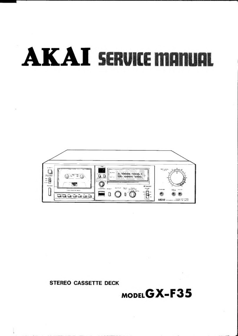
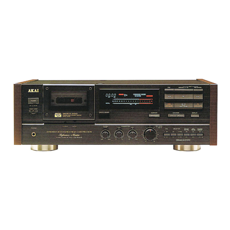
Akai X-355 User manual

MODEL
X-355
OPERATOR·s
MANUAL
CROSS
FIELD
'H,
EAD
'
SOLID
STATE
AMPLIFIER
4 -
TRACK
STEREOPHONie
SOUND RECORDER '
AND
REPRODUCER

TABLE' OF CONTENTS
I GENERAL INFORMATIONS
1.
SPECIFICATIONS
·
········
········ ····
··
·· ·
····
···
......
®
2.
NOMENCLATURE
......
·
......
.. ....··.. ·....
......
·..
..
@
3.
CROSS-FIELD
HEAD
........
.. ......
........
...
.........
@)
4.
4
-TRACK
RECORDING
jPLAYBACK
......
..
....
®
5.
TROUBLE
SHOOTING
................
·
................
@
6.
VOL
TAGE
AND
CYCLE
CONVERSIOI\'
.. ....
(j)
.Il
OPERATING INSTRUCTIONS
1.
TAPE
LOADING
...... ....
..............
..
................
®
2. PLAYBACK
............................
··.. · .. ·.. · ·.. ...... ®
3.
PLAYBACK
USING
EXTERNAL
SPEAKERS
OR
AMPLIFIER
.. .. .. @
4.
AUTOMATIC
ST
OP
(
DECK
ONLY
)............... @
5.
AUTOMATIC
SHUT-OFF
(DECK
AND AMPLI
FIERS
)·.. ··· @
6.
AUTOMATIC
REVERSE
(
METER
)
......
..
.......
@
7.
AUTOMATIC
REPEAT
(
METER
) .........
.....
.. .. @
8.
AUTOMATIC
REVERSE
OR
REWJ:,\/0
(
METALLIC
SENSING
TAPE
)...... @
9.
i\UTOMATIC
SHUT
-OFF
WITH
REVERSE
AND
REPEAr-
.....
@
10
.
MANUAL
RE:VERSE
OR
REPEAT
...............
@
Il.
RECORDING
........
·......
.......
·......·
............
.
.....
@
12.
RECORDI:,\/G
FROM
DISCS
.....................
..
. @
13.
RECORDING
FROM
AN
EXTERNAL
AMPLIFIER
·.... @
14.
RECORDING
FROM
ANOTHER
TAPE
RECORDER
......
@
15
.
MONITORING
..........
.......
..........................
@
16.
REVERBERATION
...........
.......
.
........
.
.......
...
@
17.
SOUND
ON
SOUND
...............
·.....·.. ... ...
......
@
18.
SOUND
WITH
SOUND
.
..............................
.. @
19.
FAST-FOR
WARD
AND
RE'.v!ND
.................
. @
20.
TAPE
SPEED
CHANGE
.
..........................
.. .... Q
21.
HEAD
CLEANING
.. .. ....... ... · · ......... .
..........
@J
22.
HEAD
DEMAGNETIZA
TION
.. ·.. .... ·.. .. ....·....· •
23.
TRANSISTOR
PROTECTION
-
........
·
.............
· @
24.
VENTILATION
.... ..
··
....·.. ·
.. ..
....··
..
.. ...... ..
..
.. ···
@>
mACCESSORIES
1.
ACCESSORIES
OPTIONAL
....
..
...·
......
·
..........
@
2.
ACCESSORIES
SPEAKERS
...........................
@
3.
ACCESSORIE
S
STANDARD
.. .. .
.....
.. ....
.......
@
lV
LUBRICATION CHART .......
..
......
..
.....
..
........... ®
V CONNECTING DIAGRAM................................ ®
VI
SCHEMATIC
1.
MECHANISM
UNIT
.....
.. .. .. .....
....
..
..............
@
2.
AMPLIFIER
UN
IT
..........
·.. ·.. ...... ·
....
.......... .. @

Tape
Speed
Frequenc
y Response
Signal
to Noise
Ratio
Wow and
Flutter
Pl
ayb
ac
k only)
Equalization
Cross Talk
Distortion (Total Harmonies)
Head
··········
··
Cross-Field
Motor
Us
ed
Timing
Accuracy
Recording Sensitivity
Power
Output
Tran
si
st
or
Used
Fast-Forward
and
Rewind
Ti
me
Internai
Speakers
Power
Requirements
We
ight
(Net)
Dimensions
1.
SPECIFICATIONS
3
-3
/ 4,
7-1
/ 2 and 15 ip
s.
30 to
24
,000 e
ps
± 3
db
at
7-1
/ 2 ips.
30 to 18.000 eps ± 3
db
at 3-3/ 4 ips.
Better than
47
db at normal
pl
ay.
L
ess
than 0.08%
RMS
at
7-1
/ 2 ip
s.
at normal, rever
se
pl
ay.
1 GENERAL INFORMATIONS
Better than
45
db
at
reve
rs
e play.
L
ess
than 0.14%
RMS
at 3-3/ 4 ip
s.
Correct equa
li
zation for
pl
ayback
of
tap
es
recorded to the
NA
B curve.
L
ess
than -
82
db
(Mona
ura
l) L
es
s than
-45
db
(Stereo)
Within 4.0% at 1,000 e
ps
0
VU
at
10
watts.
*R
ec
ording Head : Inline 4
Tr
ack Stereo and
Monaur
al,
low impedan
ce
135 ohms
at
1,000 eps.
*
Pl
ayback Head : Inline 4 track tereo and monaural,
low impedan
ce
1,
000
ohms at 1,000 ep
s,
insta
ll
ed on an automa
ti
c shift de
vi
ee.
*Erase and
Bi
as Head : lnline 4 track stereo, low impedance
750
ohms at
90
kc.
H
ys
tere is
sy
nchronous 2 speed (4.8 pol
e)
motor for c
ap
stan driv
e.
Two 4-pole induct
io
n motors for fast.forwa
rd
and
re
wind.
±
0.
3%
at a
li
tape speeds.
Input of
mo
re than 0.5 mY
in
MICROPHO
E jac
k.
Input
of
mo
re than 50 mY
in
LI
NE
INPUT
jack.
25 watts at Music Power on each channel, total 50 watt
s.
20
watt at Undistorted Power
Output
on
each channel, total
40
wa
tt
s.
2
SB
443
(A)x 4}
Pr
e-ampl
ifi
er
2SB 75 (B
)x
l2
2SB
75 (A
)x
2}
2SB
3
70
A(A
)x
2 Main amp
lifi
er
2S
B
33
8 (A)x 4
Rec
tifi
er
SPN
.Ol x 2
R
ec
tifi
er 12C.2 x 1
Silicone Diode x 3
2SB
3
70A
lB)x2 O
sc
ill
ator
45
sec
onds for eith
er
operation using a 1,
200
feet recording tape at 50 c
ycl
es,
36
sec
onds at
60
cy
cl
es
.
6
-1
/ 2" round, wide range speaker
s,
one
on
each channe
l.
AC
100
to
240
volt
s,
50.
60
ep
s,
60
VA
(a
t non signal) to
170
VA
(a
t maximum output:
28.
5 kg (
62
.7 pound
s)
440H x 407W x 3
100
mm
Ov
era
ll
, case
cl
ose
d.
(
17.
3/8"H x 16"W x
12.1
/ 8"0 )

GENERAL INFORMATIONS
2.
NOMINCLATURE
CD
Supply R
ee
l Shaft
®
Gu
ard Circle
@ Sp
ee
d
Ch
ange Switch
(!)
Tra
ck Sel
ec
tor Knob
@
Ta
pe
Guide
@ Tape G
ui
de Roller
(j)
Upp
er Head Cover
@ Lower Head Cover
® Remote Control Socket
@)
Power Button
@ Stop Button
@ Rewind Button
@ Play Button
® Fast-Forw
ard
Button
@ R
ec
ord
Saf
ety Lock
@ Record Safety Button
@ Microphone J ack (Left)
@ Microphone J ack (Right)
@)
VU
Meter
@ Line Volume Control (Left)
@ Microphone Volume
Contro
l (Le
ft
)
@ Recording lndicator
Li
ght
@ Line Volume
Contro
l (Right)
@ Microphone Volume
Control (Right)
@ Record
Output
Button
@ Stereo He
adphone
Jack
@ Playback
Output
Button
@ Volume Control (
Left
)
@ Volume Control (
Right
)
@ Function Switch
@ Equa
li
ze
r Switch
@ Tone Switch
@ Speaker Switch
@ Repeat Button
@ Rever
se
Button
@ hut-Off Button
® Pinch Wh
ee
l
@ Capstan Shaft
®J
Rever
se
Pin ( T)
@ Rever
se
Pin ( ] )
@ Tension Arm
@ Index
Co
unt
er
@ R
ese
t Button
@ Tape Holder
@ Take-up R
ee
l
Shaft
@
Di
a!
OA
' Button
@ Tape
Count
Meter
@Se
t
Di
a!
9 Manual Reverse Button
@ Speaker Re
fl
ectors
® Line
Input
Jack (Left)
!@
Line
Input
Jack (
Right
)
@ Line
Output
Ja
ck (Left)
!§
Line
Output
Jack (Right)
@ External Speaker J ack (Left)
@ External Speaker J ack (Right)

3.
CROSS-
FIELD
HEAD GENERAL INFORMATIONS
Cross-field
head
crea
tes a sensation in
the
tape
recorder
world
by
maki
ng
a
wide
range
of
recording
which
has never been h
ea
rd
before
any tape recorder.
Usi.ng this cross-field h
ead,
Mode! X-355 provides a s
urp
rising reco
rding
performance
(3
0-24,000 eps at a t
ape
speed
of
7-l/ 2 ips and
'0-18,000 eps
at
3
-3
/ 4 ips).
vVhat is superior
abou
t cross-field recordin
g?
How
does it
differ
fr
om
typi
ca
l reco
rding
methods
as f
ar
as construc
ti
on
is concern
ed?
On
these,
exp
lana
ti
on is g
iv
en
below in
se
qu
en
ces:
In
the typi
ca
l recording system,
the
signal c
urr
e
nt
a
nd
th
e
bia
s c
urr
en
t are
combined
tog
et
her
and app
li
ed to
the
recording h
ead
.
(Ref
er
to
Di
ag
ram
1.
)
It
is weil known that
th
e
purpose
of
bia
s c
urr
en
t
is
recording
at high
se
nsitivity with a signal
applied
on the tape, with no distortion
a
nd
minimizing noi
se
generation.
However, the bias curr
ent
providing
such
an
advantage
also has
an
und
esir
ab
le
charac
tor
.
That
is,
th
e wide
magnetic
field
of
the
bias
current
affects the r
ecorded
signal, resulting in
weakening
or
even erasing the signal.
Thi
s
phenomenon
is
particularly
noti
ceab
le
at
high frequencie
s.
ln
the
cross-field system,
the
signal c
urr
e
nt
is
app
li
ed
to
th
e reco
rdin
g h
ead
while the bias c
urr
e
nt
is
app
li
ed
to the bias
head.
These
two heads
are
l
oca
t
ed
in
different
positions, as
dete
rmind int
er
-relatively, so
that
th
e ma
gnetic
field
of
the bias w
ill
n
ot
affect
the signal recorded on
the
tape, even
when
a sufficie
nt
bias
is
app
lied.
This
a
ll
ows
th
e recorded signal to
rem
ain on
th
e
tap
e with
high fidelity.
Di
ag
ram
1.
Or
dinary
recording
system
Diagram
2.
Cross-field
recording
system
Signal
_@_
~:
biao
Direction
in
W
hich
tape
is
t
ransported
.
__@_::~
({\))
Crossfield
~
Bias
head

GENERAL INFORMATIONS 4.
4-TR
A
CK
RECORDING/PLAYBACK
1
2
3
4
Th
e
AKA
I X-355 employs a four
tr
ack sys
tem
th
at
ca
n be used for e
ith
er ste
reo
or
mo
na
ur
al rec
ord
ing a
nd
playback.
Fig. 2
® 1
1
1 , -
Fi
r
st
track
Th
e d
es
ired
tr
ack or tracks are
se
l
ec
ted
by
the
TRACK
S
EL
EC
TOR
KN
OB
. @
~
1
Second
track
( }
Tape
width
1
Third
track
\
....
Fourth
track
-
4-
Track Stereo Recording/
Pia
yback
Stere
ophon
ie rec
ording
/ playback req
uir
es
th
e simul-
taneous use
of
two
tr
ac
ks
. Set the
TRACK
SEL
E
CTOR
KNO B @ to "
STEREO
".
Th
e first ster
eo
ph
onie rec
ord
-
ing/ playback takes place on
tr
acks 1 a
nd
3, a
nd
th
e
sec
ond
on
tr
acks 2 and 4 a
ft
er
th
e reels have been
turn
ed over.
4-
Track Monaural Recording/
Pia
yback
1
2
3
4
Th
e
monaur
al rec
ording
/ pl
ayba
ck
tra
ck
se
qu
ence should be
1-
4-3
-2
.
(A). Set
th
e
TRACK
SELEC
T
OR
KNO
B @
to
" 1
-4
".
o/Y-$1·
4
3
~2
Th
e first
mon
a
ur
al rec
ording
/pl
ay
back tak
es
place on t
ra
ck 1, and
th
e second on
tr
ack 4 a
ft
er
th
e tape reels have been tu
rn
ed over.
(B
).
Turn
th
e t
ape
reels over.
(C). Set
th
e
TRACK
SELECTOR
KNO B @ to
"3
-2".
Th
e
third
mon
a
ur
al recording/ playback takes place on
tr
ack 3, a
nd
the
four
th
on
tr
ack 2 a
ft
er
th
e t
ap
e reels h
ave
been
turn
ed over.
Th
e X -355 d
O{
S not reccrd in the reve1se di
re
ction. Using reverse
pla
yback, it is r ot r.e<essary ta
turn
th
e ta
]::e
re
el
s over.
Wh
en the
X-355 begins rever
se
playba
c
k,
the playback head is a
utom
ati
ca
ll
y shifted to
th
e remaining t
ra
cks.
©
4
3
2
®
--
--------
-------
@
1
m~'77777777777777T.17777?77777~77777=.
4 -
2 3
~-\~%---
2

S.
TROUBLE
SHOOTING
GENERAL INFORMATIONS
IMPORTA
!
T:
READ
THE
OPERATING
IN
TRUCTIONS
CAREFULLY
BEFORE
OPERATING
YOUR
RECORDER
.
Th
e symptoms
li
st
ed
below
do
not necessaril y indi
ca
te a
malfun
c
tion
of
yo
ur
t
ape
r
eco
r
de
r.
If
your
ma
c
hin
e e
xhibit
s any
of
th
ese
sy
mpto
m,
takc the indic
at
ed action.
Los
of
sensitivity
or
ton
e
qu
alit y m
ay
be
du
e t
o:
Dusty
or
dirty
h
ea
ds - cl
ea
n
th
e h
ea
cl
s.
Reversed tap
-pl
ace
th
e
dull
s
id
e
of
the tape to
ward
th
e heads.
l
mproper
vo
lt
age-
check volt
age
input
and a
dju
s
tm
ent.
B.
lrr
eg
ularit
y of
th
e ta pe
tr
ans
port
may
be
clu
e
10:
Grim
e a
dh
e
ring
to
th
e h
eads-
cl
ea
n the h
c.:a
ds.
Oil
on
the
ca
pst
an
-cl
ean
th
e
ca
pstan.
Dirty t
ape
s
urf
ace
- use a
clean
ta pe.
Be
nt
take
up
ree
l - s
tr
a
ighten
th
e takc
up
ree
l.
C. If
yo
ur
machine will not r
eco
rd
, insure that
th
e following are in
th
e c
orrect
position :
RECORD
SAFETY
B
UTTON
@
Mic
rophon
e
plug
s
O.
If
yo
ur
machin
e
wi
ll
not r
ep
r
od
uce, insure that
th
e following are in
th
e
co
rr
ect position :
PLAYBACK
OUTPUT
B
UTT
O N @
S
PEAKER
SW
I
TC
H @
Lubri
cate the
X-355
a
ft
er
every
1,000 h
ou
rs of use.
If any problem arises, take
your
ma
chine
to
th
e a
uth
orized
AKA
I
agent
in
your
ar
ea
or
to
th
e Service
Departm
e
nt
of
th
e
AKAl
Company
in
Tok
yo,
J
apa
n.

GENERAL INFORMATIONS
6.
VOLTAGE
AND
CYCLE
CONVERS
I
ON
1.
Voltage
Th
e
VOL
TAGE
S
ELE
C
TOR
switche are l
oca
te
cl
un
th
e b
ac
k of
th
e rec
ord
er right
abo
ve
th
e
fu
se ho
lc.
ler
. T o s
el
e t
an
op
era
tin
g voltage,
remove
th
e volt
age
selector
cover
plate and set
th
e
pr
oper volt
age
on
th
e
tw
o switch
es
o
th
at the d
es
ircd vo
lt
age
shows t
hr
ough
th
e
over
plate win
do
w
Th
t>
rotary swiu:h
mu
st be pulled o
ut,
rotated, a
nd
reset at
th
e desired position.
IF
TH
E
RECORDER
IS
OPERATED
ON
THE
I
NCORRECT
VOLTAGE
,
SER
IO US
DAMAGE
MAY
RE
ULT.
C'.\l'TlON
:
Fig. 3
2.
Cycle
'ha
nge
fu,e
FL
'
"d
~
:
;,uurd
1ng
tu
\
'
Uit~gr;.
1
(~l
\'
111
1:!0 V
3.
\
2()0
\ .
[<)
:!
1(1
\ '
1.
j .\
Fi
g.
4
Th
e X-355 c
an
be
op
erated
on
eith
er 50
or
60
cycle alte
rnating
current.
Th
e r
ea
r
co
ver
panel
(
Figur
e 5)
of
th
e rec
order
mu
st be re
mov
ed to
make a cycle c
onv
ersion.
Fo
r 50 cycle
op
eration, loo
se
n
th
e
knurl
ed screw
on
th
e belt guide and
oo
sition
th
e belt so it rides
on
th
e
low
er
driv
ing
tr
acks
of
th
e flywheel and
motor
bu
s
hing
(Fig
ur
e 6
).
For
60 cycle
operation,
loosen
th
e
knurled
sc
rew and
po
s
ition
th
e belt so
it rid
es
on
th
e
upp
er
driving
tr
acks of
th
e Ayv
.r
heel and
motor
bu
s
hing
(
Figur
e 7). After
th
e belt is
pro
perl y
po
s
ition
ed for e
ith
er
oper
ation,
ti
ghtcn
th
t
knur
led screw a
nd
reset
th
e two siide switches l
oca
ted n
ea
r
th
e
Ay
wheel and
th
e volt
age
se
lec
tor
cover panel.

VOL
TAGE
AND
CYCLE
CONVERSION
GENERAL
INFORMATIONS
Fig. 5
50 Cycle
60
Cycle
Fi
g.
6
Fi
g. 7
@
-----------

OPERATING
IN
STR
UC
TIONS
Pl
ace
th
e reel
with
t
ape
on
th
e
SU
PPLY
REEL
SI-
lAFT
CD
and
an
e
mpty
reel
on
th
e
TAKE-UP
REEL
SHAFT
@. Pull clown on
th
e
LOWER
HEAD
COVER
@ and
thr
ea
d the ta pe as s
hown
by
th
e
dott
ed line in
Fi
g
ur
e
8.
After the ta pe has been
thr
ea
ded,
pu
sh
th
e
LOWER
HEAD
COVE
R @
ba
ck
up
into
position.
Wh
en the
record
er
is u
se
d in
th
e verti
ca
l
po
sition, the
Rubb
er
Reel 1-Iol
ders
mu
st be u
se
d.
B
es
t re
ording
r
es
ults are
obt
ained with new t
ap
e.
Stereo
Conn
ec!
th
e power corel and
Jo
ad a ta pe.
(A} Push
th
e
POWER
B
UTTO,
@).
(B) Set
th
e
TRACK
ELECTOR
KNOB
@
to
"
STEREO
".
(C) Set the S
PEED
C
HANGE
SWITCH
®
to
7
Yz
or
3-3/4 as re-
qu
ested.
(D) Set the F
UNCT
IO !
SW
I
TCH
@
to
"
STEREO
'
·.
(E) Set
th
e
EQUALIZER
WIT
CH @
to
7~
2
or
3-3/
4.
Th
e
EQUALIZER
SW
I
TCH
@ and
th
e
SPEED
CI
-
lANGE
SW
I
TCH
®
mu
st ha
ve
th
e same
se
tting.
(F) Push
th
e
PLAYBACK
O
UT
PUT
BUTT0:'-1 2
(G) Set the
SPEAKER
SWITCH
@
to
"
ON
".
Op
en
th
e
SPEAKER
REFLECTORS
-o
to
fun
y-five degrees.
(H) Push
th
e
PLAY
BU
TTON
@.
(1) Ad
ju
st
th
e
VOLUME
C
O:'-JTROL
KNOB
S @, @
to
cl
es
ire
cl
vo
l-
unle.
IJ
) Set the
TONE
SW I
TCH
@ to
"FLAT
'
or
·'BAS
S"
as
cl
es
ire
cl.
Mona
ural
For
monaur
al
pl
ay
back, s
ub
s
titut
e
th
e following steps for steps (B) and
(0 )
of
th
e stereo
pro
ce
dur
e, and follow
th
e r
es
t
of
th
e stereo
pro
ce
dur
e.
(B) Set
th
e
TRACK
SELECTOR
KNOB
@
to
"
1-4
"
or
"3-2" as re-
quir
e
cl.
(D) Set
th
e
FUNCTION
SWITCH
@ to "
MO
t 0 ".
Onl
y
th
e le
ft
c
hannel
amplifier is u ed for
monaural
playback.
1.
TAPE
LOADING
2.
PLAYBACK Fig 8
F
ig.
9

®
3.
PLAYBACK
USING
EXTERNAL SPEAKERS
OR
AMPLIFIER OPERATING INSTRUCTIONS
Though
yo
ur
AKAI
X-
355 has two internai speakers, a pair
of
either
8.Q
or 1
6.Q
hi
gh
fid
el
it
y external speakers will en
ab
le you to enjoy
th
e
b
es
t s
ound
reprodu
ction.
A.
ln
se
rt
th
e plugs from the exte
rn
al sp
ea
kers
into
th
e
LEFT
and
RIGHT
EXTERNAL
SPEA
KER
JACK
S
@,
@.
Wh
en
th
e sp
ea
k
er
plug
s are in
th
e speaker jacks,
th
e r
es
p
ec
tive in-
ternai
spea
kers are
inop
erative.
B.
Set
th
e
SPEAKER
SWITCH
@
to
"0
1
".
For
stereo
playba
ck,
th
e e
xt
ernal
sp
ea
kers should
be
epa
rated by
Fig. 10
at
!east
se
ven feet (
Figure
10
)
Fig.
Il
Fig. 12
If
an external stereo
amp
lifi
er is u
se
d for play
ba
ck, connect
th
e
LEFT
and
RIGHT
UNE
OUTPUT
J
ACKS
@),
@ to
th
e Le
ft
and
Right
Aux
Jacks
of
the Amplifier (
Figure
Il
).
4.
AUTOMATIC
STOP
(DECK
ONL
Y)
Th
e
TENS
I
ON
ARM
@ is
connec
t
ee!
to a micro-sw
it
ch
th
at
automa
t-
ically s
top
s
th
e deck
il
th
e ta pe should
break
, pile
up
,
or
pass er.tirely
thr
ough
to th
e take
up
ree
l.
Und
er
norm
al
op
e
ratin
g co
ndition
s,
th
e
a
rm
will be held in
th
e
app
r
ox
imate
po
sition in
dicated
in
F1g
ur
e
12
@.
If
the
a
rm
r
eac
h
es
th
e
po
sition as shown in
Figur
e
12
<!)),
the micro-switch
w
ill
function
and
stop
th
e dec
k.

OPERATING INSTRUCTIONS
S.
AUTOMATIC
SHUT-OFF
(DECK
AND
AMPLIFIER
S)
When
the
SHUT.OFF
BUTTON
@ is
push
ed in (
Figure
12
@),
the
deck
and
th
e ampli
fie
rs are conn
ec
ted
to
th
e
TENSIO:-i
ARM
@ micro-
sw
it
c
h.
If
the
tap
e should
br
eak, p
il
e up.
or
pass e
ntire
ly
thr
ough
to
the
tak
e
up
reel,
th
e
TENSION
ARM
@ will reach
th
e
po
sition
shawn in
Figure
12
® and the
de
ck
and
amplifiers w
ill
be
turn
ed
off
a
utom
atica
ll
y.
L..P.;.O;IL.
••
..
v-"
..
'-";_TooF
...
w;_;o;_
__
..,:R~fP~I~Aic__._~
REVR!,
SHUI
Otr
6.
AUTOMATIC
REVERSE (MEYER)
i\utomati
c ·
·e
ver
se
is used f
or
pl
ay
ba
ck only.
Wh
en the meter is used
for
au
t
om
a
ti
c rever
se
th
e
X-
355 w
ill
give co
ntinu
ous playback in
bath
direc
ti
ons
betw
een any two
po
ints (A and B)
se
lected on the
tap
e.
(A) Push in on
th
e
DIAL
OFF
BUTTON
@ and rotate it clockwise
until
th
e black index mark
point
s s
tr
aig
ht
up
.
(B) Align the '·0" on the
TAPE
COUNT
MET
ER
@a
nd
th
e r
ed
index mark on the
SET
DIAL
@ with the
bl
ack index
mark
on
th
e
DI
AL
OFF
B
UTTON
@ (
Fi
g
ur
e 13@)
Thi
s st
ep
es
t
ab
li
shes
point
A on the tape.
(C)
Advance
the tape,
by
eith
er
th
e PLAY
BUTTON
@
or
th
e FA
ST
.
FOR
WARD
BUTTON
@.
As
th
e tape feeds forward,
the
TAPE
COUNT
METER
@
mav
es
counter clockwi
se
as sh
awn
in
Fi
g
ur
e 13® .
Push
th
e S
TOP
BUTTON
@ when
th
e tape has a
dv
anced
to
the
de
sired
po
int ll.
(0 ) Rotate
th
e
SE
T D
IAL
@ until its red index m
ar
k is a
li
gned
with
th
e "
0"
on
th
e
TAPE
COU
NT
METER
@ as sh
awn
in
Fi
gur
e 13@.
(E) Push
th
e R
EVE
R
SE
B
UT
TO
N @ (
Figur
e 13@)
(F)
Using
th
e
REWI
ND
B
UTTON
@, rewind
th
e tape
ba
ck
to
th
e
sta
rtin
g point A.
As
th
e tape rewinds
or
pl
ayb
ack
in
re
ve
rse, the
TA
PE
COUNT
METER
@
ma
ves clockwi
se
.
Th
e sta
rtin
g po
int
A is reached
when
th
e "0" on
th
e
TAPE
COUNT
METER
@ is a
li
gned with
the black index
mark
on
th
e
DIAL
OFF
B
UT
TO
N
@.
(G) Push the PLAY B
UTTON
@.
The
X-
355 w
ill
n
ow
pl
ayba
ck fr
om
po
int
A to po
int
B, and
up
on
reaching point B will rever
se
it
se
lf
and pl
ay
ba
ck to poi
nt
A where
it w
ill
reverse it
se
lf
a
ga
in for pl
ayb
ac
k to po
int
B.
Thi
s operation
will
continue
a
ut
oma
ti
ca
ll
y,
as sh
aw
n in
Figur
e 13@,
until
th
e
STOP
BUTTON
@ is
pu
s
hed
Wh
en
th
e
PL
AY B
UTTON
@ is
pu
shed a
ga
in, pl
ayba
ck w
ill
res
um
e in the forward
dir
ec
ti
on
until
re
ve
rsai occ
ur
s at poi
.1
t B.
®
13

NOTE:
When you desire the reverse pl
aybac
k operati
on
by
usi
ng the Tin-foi! ensing
Tape,
be sure to check and see
ihe
Set
Dia! (A) and T
ape
Co
unrer Meter (B) is not
se
t with1n the
ra
nges as shown bel
ow
Fi
gures 1 and 2
respective!y.
If the
et
Dia
! ( ) and T
ape
Co
unr
er
Me
ter rB) i
se
t
wi
thin t
ha
l range neith
er
case the reverse pl
ay
back opera
ti
on
w
ill
work.
(J) T he red In
de
x Pointer on the Set
Di
a! (A) is
se
t within the range of " 1-0-
11
" on the T
ape
Counter Meter
lB) as hown by the
do
ttcd
li
ne in F
ig
ure
1.
12} The
"0''
on the
Tape
Cou
nr
er Met
er
rB) lies ' ithin the range as sh
ow
n by the
do
tted line
in
Fig
ur
e
2.
DIAL~
~
OFF
~
c
(Fig. 1)
1
1
1
1
A
B
(Fig. 2)
\ \ \ \ \
__
,.:).

AUTOMATIC
REVERSE
(METER)
OPERATING INSTRUCTIONS
NOTE:
ln stcp (C), if the
PLi\
Y
BUTTO
@ is used to advance
the
rape, it i
not
necessary
to
push the
TOP
BUTTON
@
at
point
B.
p.
proarhing the
de
sir
ed
point
B.
p
e
r~
rm
oteps (0 and (E).
ln
st
ep
(C),
rotate,
the
SET
DIAL
4 c
ount
er
clo
ckwise until its r
ed
index
mark
has s
li
gh
tl
y pa
·se
d the "0"
on
the
TAPE
C
OU
NT
ME
TER
@.
Th
e X.3S5 will begin re
ver
se
play
as soon
as
the "0" a
li
gn irse
lf
with
th
e
red index mark.
Step
1F1
and
(C l are not necessary, however, the
inform
a
ti
on c
onr
ained there uncler is appli
ca
bl
e.
1
\n
a
lt
e
rn
at
.:
pro
ced
ur
t:
for au
toma
t
ic
reverse
is
tol
et the
gradua
ted
Ti\PE
COU:--!T
METER
, r
epresent
2.400
feet of ta p
e.
Approximately
2,375
f
ec
t is the
maximum
le
ngth
of
tap
e
th
ar can
be
rever
sed us
ing
ch
e
TAPE
COUNT
METER
@
Not
e, as in Figure 13@
and
steps (BJ
and (D). that if th
ere
wc::rc::
2.
·
WO
feet
between
points A
and
B,
the
TAPE
CO
NT
METER
@
and
the
SET
DIAL
.1
would
be
unable
to distinguish point A
fmm
point
B.
Th
e
int
ervals between
numb
ers
repres
e
nt
200
feet.
.
ub
stitut
,;
the following for stt:p · (Cl
an
tl (f
).
( ) Manua
ll
y
rotat
e the
TAP
E
COU
T
METER
1
coun
ter clockwise
unti
lth
e
number
tha r
repr
esents the
cl
es
ired ta pe foot
age
between
points A
and
Bi
s a
li
gned
with
th
e black
ind
ex mark
on
th
e Dl
AL
OFF
BUTTO
6 (
Figure
l3<Ii)
shows
650
feet).
(F) Manua
ll
y
rotat
e the
Tr\PE
COUNT
METER
1 cio kwise
until
the "
0"
is a
li
gned
with
the
black
ind
ex ma
rk
on the 1 !
AL
OFF
BUTTO
":6'.
7.
AUTOMATIC
REPEAT
(METER)
Automntic
repeal
is u
se
d for
playb
ack in the
fon
·vard
di
r
ection
only.
Wh
en the
meter
is
lJ
Sed
for
automan
c
repeat.
the
X-355 will
continu-
ously repeat
the
portion
of
lape
from
point
A
to
point
B
by
pl
aying
ba
ck in the fow
ard
direction
from
point
A
to
point
B,
rewind
ing it
sdf
to
po~n
!
A and pl
aying
ba
ck
again
to
point
B.
Th
e
oper
ation will co
ntinu
e a
uroma
tically
unti
l
th
e
STOP
BUTTON
@
is
pushed.
Wh
en the
PLAY
BU"rTON
3 i
pushed
aga
in,
playback
wi
ll
r
es
ume
in the forward
direct
ion
unt
il
re
winding
occut
·s
at
point
B.
Th
e
pr
oced
ur
e for a
ut
oma
ti
c repeat is the
sn
me as for a
utom
a
ti
c n' verse exc
ep
t
for
· step (E).
Subs
tillle the following for st
ep
lE
).
Œ
).
Pu
sh the
H.EPEi\T
BUTT
1
~
:/
Fi
gure
13 ;.

OPERATING INSTRUCTIONS
8.
AUTOMATIC
REVERSE
OR
REWIND
{METALLIC
SENSING
TAPE)
Autom
a
ti
c reverse
or
re
wind
wi
th
metallic
se
nsing t
ape
is u
se
d for pl
ay
-
ba
ck only.
Th
e sensi
ng
tape
method
is
co
nve
nient
if
th
e
tap
e in u
se
is
too long
to
be meas
ur
ed by
th
e
TAPE
COUNT
METER
@.
(A)
Pu
sh in on
th
e
DIAL
OFF
BUTTON
@ a
nd
rotate it co
unt
er clock-
wi
se
un
til it
pop
s out.
(B) Push
th
e
REVERSE
BU
TTON
@ or
REPEAT
BUTTON
@ if
re
wind
is des
ir
ed.
Thi
s step de-activetes
th
e
TAPE
COUNT
METER
@.
(C) Splice a
two
inch piece ot metallic
se
nsing t
ape
to
th
e e
nd
or
at
th
e
d
es
ir
ed
rever
se
or
re
wind
point
of
th
e t
ape
in u
se
. Revesal
or
re
wind
will
occur
when
th
e meta
ll
ic
se
nsing ta pe makes s
im4ltan
eo
us
c
ontact
with
th
e
REVERSE
PINS
( I ) a
nd
(
)[
) @, @. Rever
se
(pla
yba
ck)
or
re
wind
will c
ontinue
unti
l
th
e e
nd
of
th
e tape passes
th
e
TENS
I
ON
ARM
@a
nd
th
e
de
ck is s
hut
o
ff.
Fig.
14
9.
AUTOMATIC
SHUT-OFF
WITH
REVERSE
AND
REPEAT
(A)
If
th
e
REVERSE
BUTTO
@
and
th
e
SHUT
-
OFF
BUTTON
@ are
both
pu
shed in,
the
X-355 will re
ver
se
at
th
e
po
i
nt
determincd
by
th
e
TAPE
COUNT
METER
@
or
th
e me
ta
ll
ic
se
nsing ta pe a
nd
playba
ck in rever
se
un
til
th
e end
of
th
e tape
pa
sses
th
e
TENSION
ARM
@a
nd
the
deck
a
nd
a
mp
l
ifi
ers
are
s
hut
off.
(B)
If
th
e
REPEAT
BU
TTON
@
and
th
e
SHUT-OFF
BUTTON
@ are
both
pu
shed in,
th
e X -355 will re
wind
at the
point
de
t
erm
ined
by
th
e
TAPE
COU
NT
METER
@
or
sensing ta pe
un
ti
l
th
e end
of
th
e t
ape
passes
th
e
TENSION
ARM
@ a
nd
the deck a
nd
amp
li
fi
ers are
s
hut
off.
(C)
lf
the
REPEAT
BUTTO
@a
nd
th
e
REVERSE
BUTTON
@ are
both
push
ed in
th
e r
epea
t function s
up
ersedes
th
e reverse func
ti
on.
(D) If
th
e
REPEAT
BUTTON
@,
the
REVERSE
BUTTON
@ a
nd
the
SHUT
-
OFF
BUTTON
@
are
ali
pushed
in, s
tep
(B)
app
li
es.

10.
MANUAL
REVERSE
OR
REPEAT OPERATING INSTR
UC
TIONS
fi
g.
15
® Pushing the
MA
UAL
REVERSE
BUTTON
@
in
the ce
nt
er
of
the
S
ET
DI
AL
@ (
Figur
e
15
@) will
put
the
X-
355
into
the rever
se
(
pl
ay
b
ac
k)
or repeat (rewind) function anytime before the "0"
on
the
TAPE
CO U
NT
METER
7 is a
li
gned with the red index mark
on
the
ET
DIAL
@.
Ma
nu
al rever
se
can also be
acc
ompl
ished by
pu
shing the
REVER
SE
BUTTON
on
the re
mot
e c
ontrol
atta
chm
e
nt
(
Figur
e
15
@).
In or
de
r for the
MA
UAL
REVER
SE
BUTTON
@
to
function, the
® bl
ac
k i
nd
ex mark
on
the
DIAL
OFF
BUTTON
@
mu
st be pointing
s
tr
aight
up
(
Fi
g
ur
e
15
@) a
nd
the
REVERSE
BUTTO
@
or
REPEAT
BUTTON
@
mu
st be pushed in .
11.
RECORDING
TEREO-
Conn
ect the power c
ord
a
nd
load a tape as s
hown
on
P
age
9.
(A) Push the
POWER
BUTTON
@).
(B) Set the
TRACK
SELECTOR
KNOB
@ to "
STEREO
".
(
C)
Set the
SPEED
CH
A
NGE
SWITCH
@ to
7-1
/ 2 or 3-3/ 4 as
re
quir
ed.
(D) Set the
FUNCTION
SWITCH
@
to
"
STEREO
".
(E) Set
th
e
EQUALIZER
SWITCH
@
to
7-1
/ 2
or
3-3/ 4.
Th
e
EQUALIZER
SWITCH
®
and
the
SPEED
CHANGE
SWITCH
®
mu
st have the sa
me
se
tting
.
(F) Push the
RES
ET
BUTTON
@a
nd
se
t the
INDEX
COUNTER
@
to
"0000".
Th
e
INDEX
COUNTER
2 provicles a reference for locating a
position
on
the ta pe.
(G) In
se
rt
the
mi
c
rophon
e plug into the
MICROPHO
E
INP
UT
JACKS
@,@.
Main tain a
di
stance of a t !east
se
ven feet between the
mi
c
roph
ones
(see Fig
ur
e 16@). Mic
roph
one
volum
e leve! m
ay
be
adju
sted and
balanced by the
MICROPHONE
VOLUME
CONTROL
KN
OB
S
@,
@.
Norm
al rec
ordin
g sho
uld
not
exceed "0"
on
th
e
VU
meters
@.
If
an e
xt
ernal amplifier is c
onn
ected a
nd
in u
e,
fee
cl
back
can
be
pr
eve
nt
ed by a
dju
sting the
VOLUME
CON
-
TROL
KNOB
S @,
@.

OPERATING INSTR
UC
TIONS
(H) Push e
ither
the
RECORD
OUTPUT
BUTTO
@ or the
PLAY-
@)
BAC K O U
TPUT
13UTTON
2 •
If
th
e
RECORD
O U
TP
T
BUTT0
1 @ is us
ed
a
nd
the S
PEAK-
ER
W IT C H @ is "
ON
", the
progr
am s
our
ce
may
be
moniwr
ed
as ir is being recordecl .
1f the
PLA
YBACK
0
TP
UT
13
U
TTO
! @ is used a
nd
the
PEAK
ER
WITCI-I
@ is "
ON
", the r
eco
rd
ed
signal will
be
moni-
torcd
as
the ta pe passes the
pl
ay
b
ac
k he
ad.
Th
e volu
me
m
ay
be
co
ntr
o
ll
e
cl
by
the
VOL
ME
C
ONTROL
K
NOBS
@ , @ . @
(1)
Pu
sh the
PLA
Y BU
rTON
@ .
!] ) Push the R
EC
ORD
SA
FETY
B
UT
TO
N
@.
Th
e
RE
CO
RD
SA
FETY
BU
TTO
@ is e
qui
ppe
cl
wi
th
th
e
RECORD
SA
FETY
LO
C K @ to
pr
eve
nt
i
na
dv
en
en
t er
as
ur
e of
recor
ded
ta pes.
Turn
the R
ECO
RD
AFETY
LO
C K @ clockwisc
un
til its
red
ma rk is a
li
gne
cl
with
the white
ma
rk on
th
e r
ecorde
r.
(K)
Chec
k tha r the R
ECORD
I
NG
IN D I
CAT
OR
LI
GHT
2 is
on
.
If the
li
gh
t i
not
on,
th
e
X-
355 w
ill
nor r
eco
rd.
(L) Push the
ST
OP
B
UTTON
@ ro st
op
rec
ording
.
T o res
um
e
record
ing,
th
e
PL
AY B
UTT
0:'-1 @ a
nd
the
RE
C
ORD
Si\
FETY
B
UTTON
@1
must be de
pr
essed
aga
in .
MO
NAU
R
AL-
F
or
mon
a
ur
al r
eco
rding, s
ub
s
titut
e the fo
ll
owing
steps
for st
eps
(B) a nd (G)
and
a
dd
st
ep
(M).
Follow
the rest
of
th
e ster
eo
pro
ce
du
re.
(B) Set the
TRA
C K
SELECTO
R K
NO
B@ to " 1
-4"
or
"3
-2"
as
re
quir-
ed.
(G )
ln
se
rt
the micr
op
hone
plu
g
inw
the L
EFT
M IC
ROPHO
E
1
PUT
J
AC
K
@.
Onl
y the left
amp
li
lî
er is used for
mon
a
ur
al r
ec
or
ding.
(M)
Tu
rn the ta pe reels
ove
r
to
r
eco
rd
on
rr
ac
k 4 or tr
ac
k 2 as
app
li
ca
bl
e.
If
th
e s
ound
so
ur
ces a re so fa r
from
the micr
op
hones tha t the
M IC
ROPHO
NE
VOLUME
C
ONTROLS
@
,@
mu
st be
turn
ed
up
hi
gh,
so
me
hum
m
ay
be
introdu
ce
cl
. T o
avo
id r
eco
rdin
g the
hum
, au
ac
h a
ground
wi
re to
th
e deck.
©
CD
RECORDING

12.
RECORDING
FROM
DISCS OPERATING INSTR
UC
TIONS
To record
fr
om a ster
eo
or mona
ur
al dise, a
CRYSTAL
PI
CK-UP
(0.
5-1
volt)
or
a
CERAM
IC PI
CK-UP
may be
conne
cted
dir
ec
tl
y to
th
e
UNE
INPUT
JA
C KS @, ®
in
step (G) of
th
e r
eco
rding
pr
oce
dur
e. If a
MAGNET
IC
CARTRIDGE
is u
se
d, it
mu
st be c
onn
ect
ed
to a
separate pre-amp
lilî
er
or e
xt
ernal amplilîer before be
in
g
co
nn
ec
ted
to
th
e
X-
3
55
LI E I
NPUT
J
ACKS
@,
1@.
VU
leve! is c
ontroll
ed w
ith
the U NE V
OL
U
ME
CO N
TROL.
@, @.
13.
RECORDING
FROM
AN
EXTERNAL
AMPLIFIER
If
an extern al ampli
lî
er or
tun
er-amplilîer comb
in
ation is u
se
d,
c
onn
ect the
TAPE
OUTPUT
l
ea
ds
of
the e
xt
ernal amplilîer
to
the
LINE
INPUT J
ACKS
@,
@ in st
ep
(G) of
th
e recording pr
oced
ure.
VU
leve! is c
ontro
ll
e
cl
wi
th th
e LI
NE
VOLUME
CONTROLS
@,
@.
Th
e
X-
35
3 w
il
l reco
rcl
any so
ur
ce
that
ca
n
be
select
ecl
on the e
xt
ernal a
mp
l
ilî
e
r.
Fi
g. 17
14.
RECORDING
FROM
ANOTHER
TAPE RECORDER
®
I
NPUT
If another X
-3
55
is u
se
cl
, c
onn
ect
th
e
LI
NE
OUTPUT
JACK
!@,!§o
f
the
pl
ay
b
ac
k m
ac
hine
to
th
e
LINE
I
NPUT
JACKS
@,®
of
th
e rec
ord-
ing m
ac
hine in step (G)
of
the r
eco
rding
pro
ce
dur
e (F
igur
e
17
a).
If
on
e
of
th
e
AKA
I
M-
se
ri
es reco
rcl
ers is u
ecl
as a pl
ay
b
ac
k machine,
c
onn
ect its sp
ea
ker j acks to the
LN
IE I
NPUT
JAC
KS
@,@
of
the
X-
355
in step (G)
of
th
e recorcling
pro
ce
dur
e (Fig
ur
e 17 b).
VU
leve! is c
ontroll
e
cl
with
the
LI
NE
VOLUME
CONTROL
@,
@.

OPERATING INSTRUCTIONS
15.
MONITORING
Step
(H)
of
the
recording
procedure
describ
es
monitoring. If a set
of
ster
eo
head
phon
es is u.
cd
they s
hould
be
of
the low
impedance
type.
preferably 8
ohm
s.
If the hea
dphone
s h
ave
rwo
se
para
re plugs, inserr th
em
in
th
e
EXTER
L
AL
SPE
KER
j t\
CK.
@>
,
1@.
Th
e
PEAK
ER
WlTCH
@ musc be •
·ON".
If
the head
phone
s
hav
e
on
ly
one
plug
in
sc
rr
it
into
th
t:
STE
REO
HEADPHO
NE
JA
CK
@
Tht;o
SPEAKER
W
ITCH
l
m
<~v
be
"0N"or
"
OFF".
l'v
loniroring
procedt
•r
es
are
the
same for n:c
ording
or
pl
aybac
k.
16.
REVERBERATION
(AJ Set the
SPEAKER
SWITCH
@
ro
"OFF
".
(B) Push
in
the
RECORD
0
TPUT
BUTTON
@ and
th
e
PLAY-
RACK
OUTPUT
BUTIO
N @.
( )
Confirm
rh
at rhere
are
no c
onne
ction.
to
the LI
:-JE
INPUT
JACK
S
@, •. Fig.
18
D ) ln
se
r1
the mic
rophone
plugs
into
the M
ICROPHO
t E
JACKS
@,
@.
(E) Adjust the
MICROPHONE
VOLUME
CO
NTROL
S
z~,@)
to
the
prope
r le
ve!
on
the
VU
meters.
(F) ln n·asc the LI E
VOLUME
CONTR
I.
S@J,@
ro a
pproxi-
mat
<>
ly
max
imum.
M•
C~
(G)
f'l•
sh the PLAY BU
TTON
@
and
the
RE
ORO
AFETY
B
TTON
@.
Th
e reve
rb
eration levet
may
be
controlled
by
the
UNE
VOLUME
CONTROLS
@,
@.
Reverb
erat
ion r
ccord
ing
can
be
m
ade
monnur
a
ll
)'
or
in st
ereo
.
MIG VOL UM
E.
~~
VÔL UME
~
1
.-----
-,
,....-
...
L 1 Ml
INI
fOR
1 1
1/
u \
1
AMPL
F
I>.
[ - \ /
L
___
_ l
..._
_
_,

17.
SOUND
ON
SOUND
Fig. 19 @
OPERATING INSTRUCTIONS
Fir
st
Recording
(A ) Set the S
PEAK
CR . W
ITCH
@1
to "
OFF".
lB
:
Confirm
that r
herc:
an: no conn
e<.:
tian ·
to
the U
NE
I:'IIP
T j i\
1(
-
@. @.
iCI Set the
TRACK
SELECTO
R K:'IIOB @ w '·1-+"
fot
· re
cord
in
g on
track 1.
tD
,>
Set
th
e
FU
. C T IO SW I
TCH
@ to
"STE
REO
".
(E) ln
sc
rt
the
microphone
plug
in the
LEFT
M I
CROPHONE
j
ACK
@.
(P)
Adjust
the
LEFT
MICROPHON
E
VOLUME
CONTROL
@ to
the
proper
level on the
VU
meter.
(
G)
Push the PLAY
BU1TON
@ a
nd
the
RECORD
S
AF
ET
Y
B
UT
TON
@ and
make
th
e first r
ecor
ding
, i
.e
. Do
-R
e
-Mi
.
(HJ
Wh
en the first recording is
comp
lete, rewind the t
ape
tO
the s
tarting
position.
Second
Recording
ilJ Confi
rm
that
the
RECORD
OUTP
T B
UTT
ON
@
and
the
PLAY
-
BA
C K O
UT
P
UT
B
UTT
O
N@
are bot
h in
the
O
UT
position.
IJ ) Set the
TRACK
SELECT
OR
K 013 @ to
''3
-2" f
or
recording
on
track 3 while list
ening
to t
ra
k
1.
IKJ Increase the L
EFT
U
NE
OL
UME
CO N
TROL
@
t0
approxi-
ma
tely
maximum
.
1L)
Conn
ect the ste
rt'O
he
adp
hones to
monitor
the first rec
ordin
g on the
left channel (
tr
ack l).
'Mi Push the
PL
AY B
Ur
rON
3
ant
l
the
RECORD
.
FE
TY
B
TTON
@
The
first r
ecord
ing will be b
eard
thr
ough the h
eadpho
ne
s.
(N) Reset the
LEFT
LI
E
VOLUME
CO
t
TROL
@ to the
prof>Cr
level
by
watching
th
e le
ft
channel
VU
meter.
(0 )
After
the reset, rcwi
nd
the t
ape
again
to the starting point.
(P) Push the
PLAY
BU
TTO
N@
and the
RE
C
ORD
AI·'E'IY
BUTTON
@.
The
second r
ecording,
Mi-Fa-
ol, is
made
on
tr
ac
k 3 as th lirst
recording, Do-Re-
Mi
,
is
monitored
in the
headphones
.
Th
e two will
be
c
ompletely
mcrgcd
on
t
ra
ck
3,
i.e., (
Do-R
e-Mi,
Mi-F
a-
So
l).
(Q )
The
thir
d and s
ub
se
qu
e
nt
recordings
are
mad
e rhe
samc::
as the
second b)' switching the
TR
CK
SE
LE
C
TOR
KN
OB
@ to " 1-4",
"3-
2"
etc.
Other manuals for X-355
1
Table of contents
Other Akai Cassette Player manuals