CONVEYOR LENGTH AND CONFIGURATION
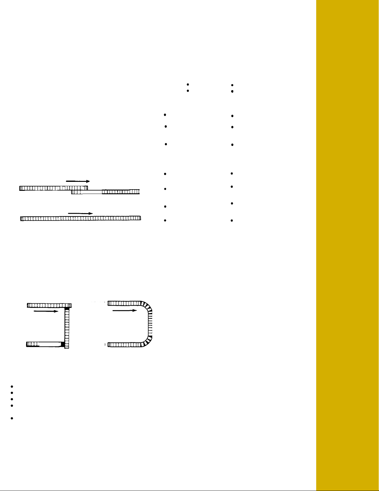
STRAIGHT -
TRANSFER END
START
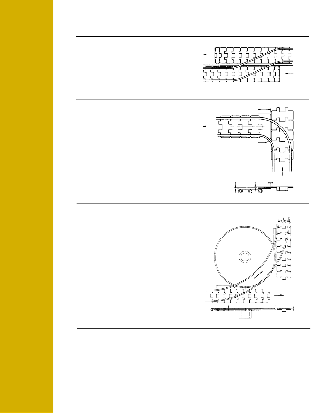
Figure A
Figure B
- A B
START START
END I I I I I I I END
Figure A Figure B
SIDEFLEXING VS
A B
VS
END
START
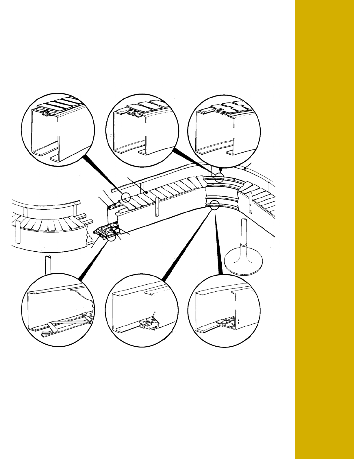
Rexnord does not build conveyors which use TableTop®chains,
nor does it specify one conveyor design over another. However,
based on many years of application experience, Rexnord is well
qualified to point out general guidelines and alternatives in
conveyor systems design, chain application and chain selection.
Conveyor systems design consists of Systems Economics and
Cost which involves:
1. Conveyor Length and Configuration
2. Chain Width and Speed
3. Overall Conveyor Cost
4. Maintenance
Begin with a review of the overall layout including space
available, structural obstructions and process machinery and the
relative positions of different machines. Then, using the following
considerations, arrive at the optimum machinery and conveyor
layout for proper utilization of TableTop®chains.
The longest, simplest configuration possible, (Fig B) is always
the best. However, sometimes short conveyors with several
transfers must be used to change speeds, change inclines,
accumulate, etc.
Use sideflexing chains and run as far as possible. This
alternative (Fig B) offers the following advantages over Figure A:
Elimination of transfers over dead-plates and turntables.
Less tipping and jamming, less noise.
Elimination of product slippage at transfer points.
Reduction of expense for attendant machinery including motors,
sprockets, etc.
Reduction of expense for attendant machinery including dead-
plates and turntables.
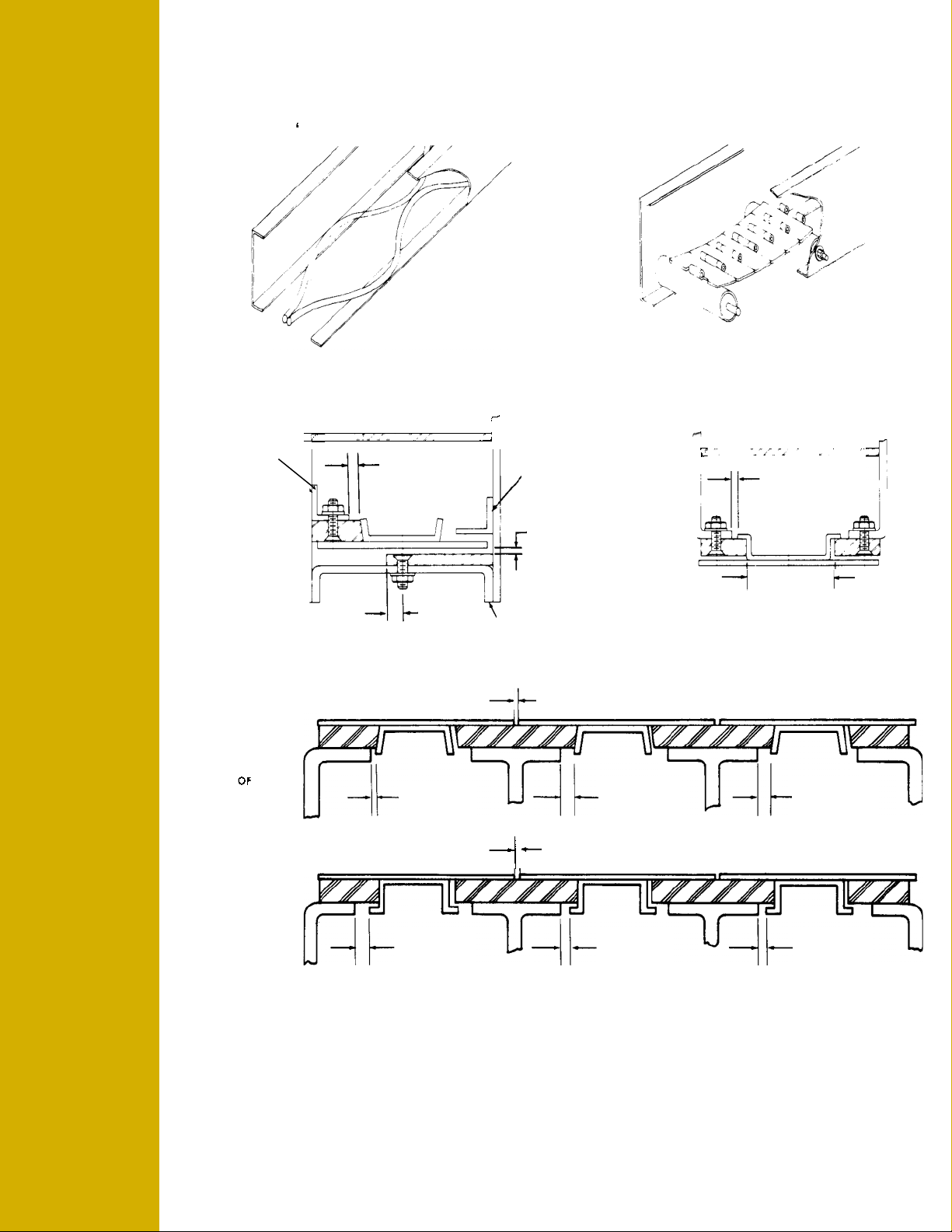
The criteria for conveyor width and speed is the number of
products which must be delivered to a location per unit of time.
The infeed and outfeed of each process machine will dictate
product flow width at the machines. But in-between, the
alternatives range from high speed-single file to intermediate
speed-multiple file on one wide chain to slow speed-multiple file
on multiple wide strands.
Weigh the advantages and disadvantages of each:
Single File Multiple File
High Speed Slow Speed
ADVANTAGES
Less expensive chain Longer chain life due to
slow speed
Less expensive initial Less chance of product
conveyor cost tippage
Longer runs In-line accumulation
less noise
DISADVANTAGES
Faster chain wear More expensive chain
More wear on products More expensive initial
when slippage occurs conveyor cost
More chance of product Shorter runs
tippage and jam-ups
Noisier Multiple chain strands may
cause transfer problems
To determine chain widths and see Page 14, Multiflex.
OVERALL CONVEYOR COST
Overall conveyor cost includes:
1. The cost of one chain versus another.
2. The cost of more efficient chains versus the cost of drives
and transfer equipment.
3. The cost of structural components of one system versus
another.
MAINTENANCE
Of course, keep in mind the future conveyor maintenance. A
system which is less expensive initially will usually require more
maintenance later on.
IN CONCLUSION
There may be more than one right way to utilize TableTop®
chains. Consider the alternatives of length, configuration, width,
speed and cost to design a system which is both economical for
the fabricator and the user.
Rex
®
Engineering Manual TT-1
INTRODUCTION
Rex®TableTop®Chains