GJD OPAL RFX User manual

GJD OPAL RFX WIRELESS 35 METRE EXTERNAL PIR
INSTALLATION MANUAL
- 1 -
THE WIRELESS OPAL RFXEXTERNAL PASSIVE INFRARED INTRUDER
DETECTOR DESIGNED TO DETECT AND TRANSMIT RELIABLE EVENT
BASEDTRIGGERS TO THEWEATHERPROOFRFX-3RECEIVER.THESE
COMBINED UNITS ENABLE THE SIMULTANEOUS OR INDIVIDUAL
CONTROL OF CAMERAS,VCR'S,DVR'SAND VIRTUALLY ALL LOW-
VOLTAGE SWITCHING REQUIREMENTS.
THE WEATHERPROOF RECEIVER WITH FRONT AND REAR TAMPER OUTPUT CAN BE POSITIONED IN LINE OF
SIGHT UP TO 150 METRES AWAY. THE ACTIVE STATE OF UPTO 3 OPAL RFX PIR'SIS CONSTANTLY
MONITORED.THESE SIGNALSAREDIRECTEDTOTHEIRRESPECTIVEVOLTFREEOUTPUTS ANDIN ADDITION
THERE ARE AFURTHER EIGHT INDIVIDUAL MONITORING AND INFORMATION OUTPUTS.
OPAL RFX WIRELESS P.I.R (GJD018)
Supply:
2 x AAA Alkaline 1.5 volt (not supplied)
Low power typical battery life two years.
Transmission - 150 metres line-of-sight:
433.92 MHz frequency - SAW stabalised
Coverage Range 10 to 35 metres:
35 x 30 mtrs max.with 90º multifunction lens
Internal adjustment 180º pan + 90º tilt.
Mounting Heights: (variable)
3 metres high for multi-beam coverage
6 metres high for curtain covage and
1.5 metres for pet immunity (mask supplied)
Processing - Non-volatile memory:
Intelligentsignalprocessing:
Digital&intergralwhitelightfilter
16millionpossibleidentification codes
Adjustments:
Detection signal (CCTV) timer 0.4 to 60 secs.
Lightlevelsignal2luxtodaylight
Pulse count 1 (2 & 3 <6 seconds)
Temperature: -20 C + 55 C
Detector Housing:
ABS high impact IP55 rated
Weight - 152 grams
Dimensions 110high x 100wide x 100 deep
RFX-3 RECEIVER (GJD017)
Supply:12VDC@35mAnominal
(9to 20VDC maximum)
Outputs (CCTV):
3 x independent channel outputs (24hr)
Selectable N/O (form A) or N/C (form B)
Individual timers 0.4 to 60 seconds after last
detection.Nonvolatile memory
Outputs(A):
3 x independent switching -ve outputs (24hr)
rated @ 250mA - 0.4 second on detection.
RF loss of signal outputs:
3 x RF/signal - ve switching rated @ 250mA
LuxOutput(S):
1 x photocell controlled -ve switching
Active 60 seconds after last detection
Tamper:
Back & Front tamper volt free output (form B)
Indication with outputs:
Independent channel active & low battery
Temperature: -20 C + 55C
Weatherproof Enclosure:
IP65 high impact ABS
Weight - 340 grams
183 high x 123 wide x 60mm deep

- 2 -
1 X
FEATURES:
1) Securewirecodetransferconnector
2) PowerSupplyinput
3) LO-outputpulsesevery5seconds
whenanybatteriesarelow
4) 3x 'A'-veoutputswhichactivate for
0.4secondondetection (24 hour)
5) 'S'output - photocellcontrolled
6) 3xRF-lossof active signal outputs.
Activates5mins.afternotreceiving
asignal froma registered detector.
7) 3xindependentvoltfreeCCTV
contacts. Adjustable0.4to60seconds.
8) Selectionjumper-Normallyopenor
normallyclosedCCTVcontacts.
9) 3xRFlossof signalLEDindicators
10) Reception-givesindicationofthe
radiosignalbeingreceived.
(a) Flicker=normal
(b) Onandoffindicatesconflictwith
otherradioequipmentonthesame
frequencyincloseproximity.
11) 3xChannelbuttons
Foruseincode transferfunctiononly.
Plusdetectionindicatorsthatlight for
thelengthoftheCCTVtimersetting
12) Batterylowindicatorcorresponding
detectionindicatorwillalsoflashevery
5secondswhenbatteryislow(see3)
13) Tamperwillactivate/
(a)whencoverremovedor
(b)displacingfromthemountingpoint.
14) Aerial
10
11
14
8
7
6
5
4
3
2
1
9
GJD
LN
1
2
3
RF3
RF2
RF1
RFX-3
RECEIVER
CCTV 1 2 3
N/C
N/O
T-20+55C
12V
35mA
N/C
TAMPER
CCTV
3
CCTV
2
CCTV
1
LO
A1
A2
A3
S
RF1
RF2
RF3
+
1213
The RFX-3Receivermonitorstheactive
stateofuptothreeOpalRFXpassiveinfra
reddetectors.
The RFX-3 Receiver can be mounted
externally or internally. The transmission
distanceof150metrescanbeobtainedifthe
detectors are in true line of sight to the
receiver. When installing the RFX-3
Receiverinternally,thetransmissiondistance
of150metreswillbereduceddependingon
thethicknessandtypeofmaterialstructure
the radio signals have to pass through or
around.
ItisadvisabletoconductanRFcontinuity
testwhenmountingthereceiverinternallyto
ensurethattheradiosignalscanbereceived
in the desired location. (RF continuity test
page5)
been transferred via the secure wire code
learninglink.Thistransferisonlyrequired
ontheinitialsetup,anysubsequentchanges
tothedetectorprogrammingwillberelayed
by radio automatically to the receiver.
(programmingchart-page5)
Wirelesstransmission.
Eachdetectortransmitsradiosignalstothe
receiver and has over 16.7 million indi-
vidualcodes.Thereceiveronlyrespondsto
the transmitter that has been linked to a
channeltoidentifyit.
The receiver can only analyse this
information after the individual code has
(fig1)

-3-
RFX-3RECEIVERINSTALLATION
Thereceiverhasfivecableinletswhichhave
individual moisture and insect blanking
plates.Therearethreedoubleandtwosingle
entry clamps for 6/8 core 5mm OD signal
cables.(seefig2)
Feedthecablefrombehindtheunitandpush
intothecableguides.Ensurethatthemois-
tureandinsectblankingplatesareinsertedin
toanyunusedcableclamps.
1.5 VOLT
1.5 VOLT
PROGRAM
BUTTON
+
1) Applythe12VDCtothereceiver
2) Plug in the link wire from the first
detector in to the receiver (see fig 4)
3) Presstherespective‘Channelbutton’
onthereceiveronce–theLEDlights
4) Within4secondspressthe‘Program
button’onthedetectoronce
5) The‘Channel’indicatorblinkstwice.
Thecodeforthat detector is stored
andregisteredtothatchannel.
6) Removethelinkwire fromthe
receiverandplugintotheaerial
transmitterinthe back of the
detector. (see fig 5)
Detectionsignals willbeimmediately
transmittedtothereceiver. (fig 5)
Repeat Steps 2 to 6 for each detector.
Tocheckwhetheracodeis stored - press
thechannelbuttononce-threebeeps
sound.
To erase a code from the receiver-press
andholddownthechannelbuttonuntil
thecontinuousbeepsend-thenrelease.
PROGRAM
BUTTON
3
V
2XAAA
RFX
-20T +55C
GJD
PROGRAM
BUTTON
3V
2XAAA
RFX
-20T +55C
GJD
LN
1
2
3
RF3
RF2
RF1
CCTV123
N/C
N/O
T-20+55C
N/C
TAMPER
CCT
V
3
CCT
V
2
CCT
V
1
LO
A1
A2
A3
S
RF1
RF2
RF3
+
PROGRAM
BUTTONS
Setup
Totransferthedetectorcodetothereceiver.
BATTERYINSTALLATION
1)RemovetheOpalRFXcover
2) Removethemodulefromthebracket
3) Removethefresnellens
4) Insert2xAAAbatteriesintothemodule
as shown.(fig 3) Put the base of the
batteryin firstthenclickthe'+'infirmly.
(fig 3)
Toreplacethebatteries–pushoutfromthe
holeson the reverse of the module.
(fig2)
(fig4)

- 4 -
1 X LUX ‘S’ OUTPUTONLY:
a) 2 lux to 240 lux. = the approximate
light level at which the ‘S’ output is
activated.
b) 24 HOUR=willoperatedayandnight.
Allotheroutputsoperatedayandnight
irrespectiveofthe‘S’outputsetting.
PULSECOUNT:
Therangeoftheunitwilldecreaseifthereis
littledifferenceintemperaturebetweenthe
movingobjectandthebackground.
1 willgivea fastresponse
2 givesbetterimmunitywithgood
response
3 giveshigherimmunitytofalse
activation
Timing 1 (2 & 3<6 seconds)
TIME'CCTV'OUTPUT
Thisisthetimeinsecondsthatthe'CCTV'
voltfreeoutputwillactivateafterdetection.
For setup purposes the respective channel
indicatorwillalsolightforthistime.Adjust
the jumper link on the RFX-3 Receiver to
selecteithernormallyopeninalarmcondition
ornormallyclosedcontacts.
CUSTOMISING
Allfactorysetparameterscanbechangedto
suitindividualrequirements.Thehighlighted
areas on the programming chart show the
factorysettingswhichsuitmostapplications.
Changes can be easily made either before
installationoronsite.Oncechangeshavebeen
madetheyarestoredinanon-volatilememory.
PROGRAMMING
Toamendyourexisting'Option'and'Setting'
1) Presstheprogrambuttononthedetector
onceforthenumberoftherequired'Option'
(e.g.range-presstwice)
2) Wait4secondsuntiltheLEDgoesout.
3) Within5seconds pressthebutton againfor
thenumberoftherequired 'Setting'
(e.g20metres-pressthreetimes)
4) TheLEDblinkstwice-thenewsettingis
saved
To amend any other options/settings repeat
steps '1' to '4'
EXAMPLE-TosettheRangeto20metres
a) PresstwicetoselectRange
b) WaituntilLEDgoesoff(4seconds)
c) Press three times for 20 metres
Six = will flashout your selected settings
Seven = will reset to GJD factory default settings
Eight/hold = will start the RF continuity test (see page 5)
Nine/hold = will generate and alternative random code ( see page 5)
AUXILIARY
OPAL RFX DETECTOR PROGRAMMING CHART
652
2
2
2
3
3
3
3
4
4
4
5
5
7 8
86 7
Press
Twice -set Range
Three -set Lux Level
Four -set Pulse Count
Five -set Time 'CCTV'
1
1
1
1
10 15 20 25 35 metres
2 5 15 30 60 120 240 24hr 'S'output
1 2 3 pulse count
0.4 1 2 4 8 25 30 60 seconds
then x
for
then x
for
then x
for
then x
for
OPTIONS
wait for indicator to go out

- 5 -
RFCONTINUITYTEST
It is advisable to test the RF signal at the
detectorlocationprior toinstallation.
ToentertheRFcontinuitytestmode-press
theprogrambuttonontheOpalRFX'eight'
times.Ontheeighthpress-'hold'thebutton
downfor5secondsuntiltheLEDgoesout
- the LED indicator will then flash and
transmitonesignalpersecondtothereceiver.
Thecorrespondingchannelindicatoronthe
receiver will also flash once per second if
thereisastrongRFlinkestablished.
Thistestmodewillautomaticallycancelin
fiveminutes.Alternativelytocancelthe'RF
continuitytest-pressandholdtheprogram
buttonuntiltheLEDlightsthenrelease.
If it is necessary to conduct a site survey
prior to installation of this equipment it is
advisable to power the RFX-3 Receiver
temporarily with a PP3 (9volt) battery.
Registeronedetector,thenconductanRF
continuity test as detailed above. As the
signals to the receiver are sent once per
second the optimum position of both the
OpalRFXandtheRFX-3Receivercanbe
easilyestablished.
CHANGINGTHERANDOMCODE
Intheunlikelyeventofanotherradiosignal
affecting the correct operation of a single
channel.TheOpalRFXdetectorcangenerate
analternativerandomcode.
PresstheprogrambuttonontheOpalRFX
nine times. On the ninth press 'hold' the
button down for 5 seconds until the LED
goesout,thenreleasethebutton
ThenerasethecodefromtheRFX-3Receiver
byholdingdownthat'channelbutton'until
thebeepsstop,thenrepeatsteps'2'to'6'of
the 'Setup' procedure to register the new
code.
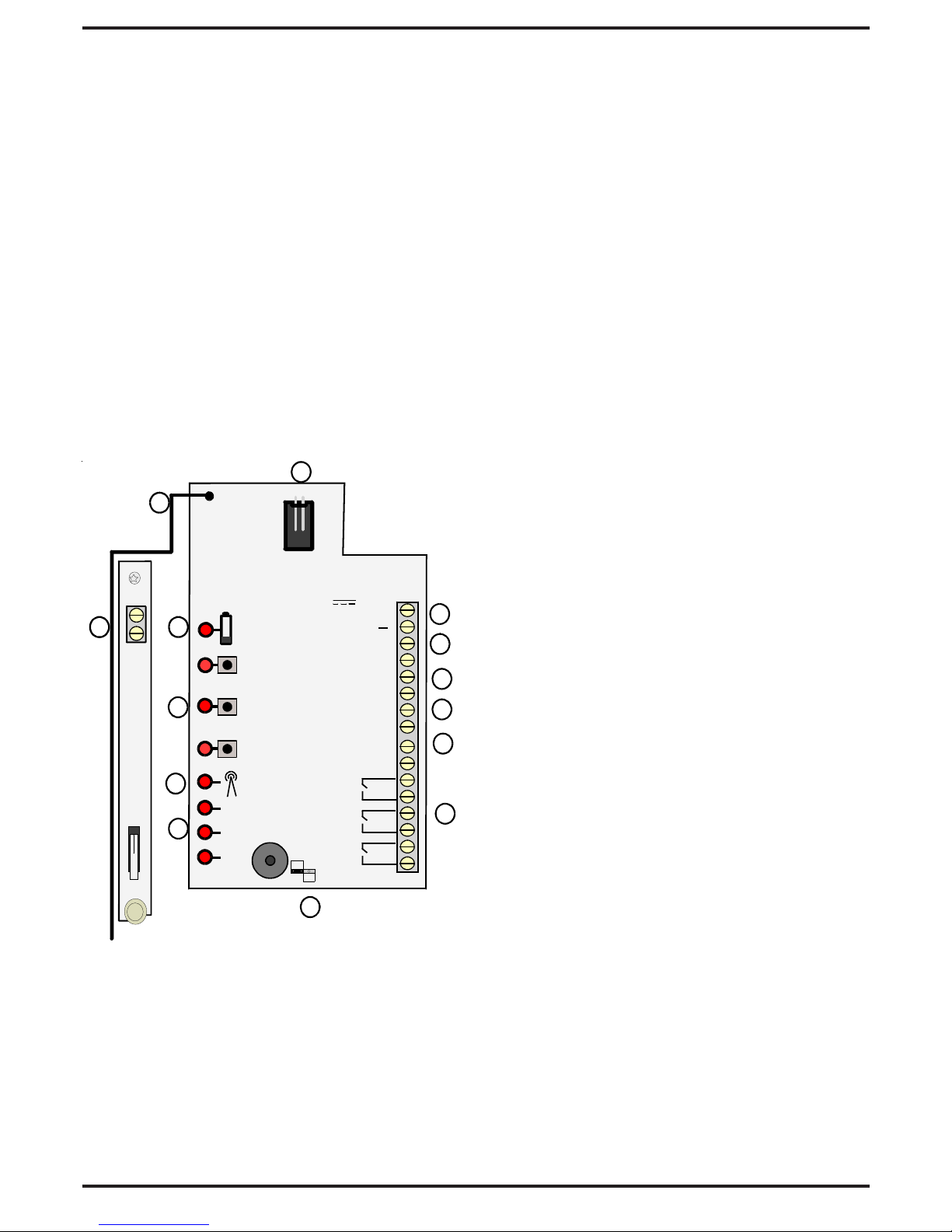
OPALRFXINSTALLATION:
Duringinstallationtheelectronicsmustbe
protectedagainstwater,astrappedmoisture
caneffectordamagetheunit.
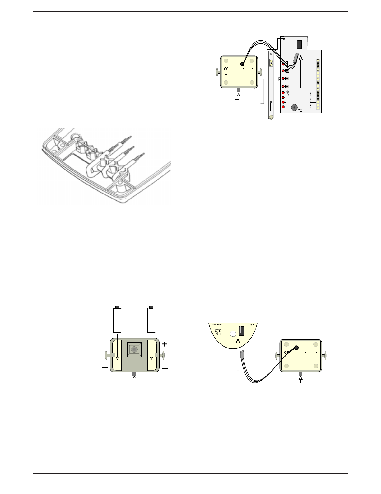
1) Firstremovethefrontpolythenecoverby
pullingforwards,thenremovethelens
modulebypullingitoutoftheforked
bracket.
2) Drillthewalltoacceptthefixingscrew
suppliedwiththewallplug.
3)Fitthehousingtoasecuresurface.Whenthe
surfaceisunevenusethe4mmspacer
suppliedto ensurethattheradiosignals
transmittedachievetheiroptimumdistance.
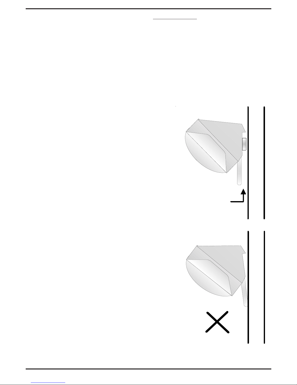
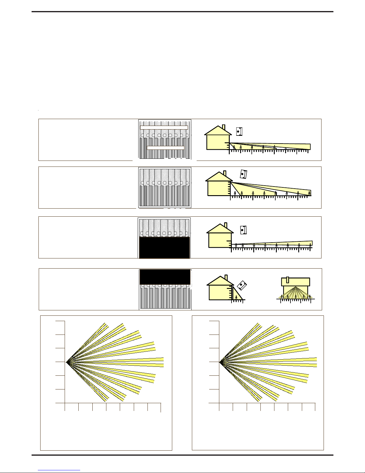
4)Alwaysensurewhenreplacingthemodule
thatitis the correctwayupfor the
correctalignmentofthebeampattern.
(Seepage7Multibeamlensdata)
TESTINGTHEOUTPUTS
(Alignmentofthedetectionbeams)
Therangeofthedetectorincreaseswith-
outthefrontprotectivecover.Therefore
thefrontcovermustbefittedtoestablish
thecorrectbeampatternalignmentand
whentestingtheoutputs.
When the 'program' button is pressed
momentarily the red indicator lights and
pulsecount'1'isautomaticallyselected.The
unitcan then be aligned.The red indicator
willlightontheOpalRFXandtherespective
Channel indicator will flash every time a
detection takes place. This test mode will
automaticallycancelfiveminutesafterlast
detection.Alternatively,tocancelthis 'walk
testmode'presstheprogrambuttontwice.

- 6 -
IMPORTANT:
Ensurethedetectorismounteduprighton
averticalsurface.Ifmountingthedetector
on a conductive or uneven surface it is
advisable to use the mounting spacer
provided.
Thiswillensurethattheaerialisabovethe
4mmclearancedistance requiredfromthe
surfacetooptimisethetransmissionrange.
MIMIMUM DISTANCE 4MM
ALIGNMENT
Passiveinfraredmovementsensorsdetectthe
temperature changes of moving objects.
Movementacrossthebeamsproducesthebest
responseandrangewhilstmovementtowards
thedetectorwouldbelessresponsive.Usethe
pan and tilt facility to accurately target the
detection zone, and adjust the range of the
detectortocovertherequiredarea.
Theclearmasksuppliedwiththedetectorcan
becutandappliedverticallyorhorizontallyto
eliminatecoverageofasinglebeam,anentire
longrangesectionorcorridorbeamforCCTV
applications. When mounting higher than
boundaryfencesmaskoffanysidebeamsthat
falloutsideoftherequireddetectionarea.Also
ensuring that no obstacles, such as walls or
large trees for example, obstruct the beam
patternview.
Astheunitdetectsachangeinheatinitsfield
of view, therefore to avoid any false alarms,
direct sunshine, trees, shrubs, ponds, central
heatingboilerfluesandanimalsshouldallbe
consideredwhensightingthedetector.Theunit
is not recommended for mounting on metal
cladbuildingsindirectsunasexcessiveheat
produceshazeripplewhichcanproducefalse
activation's.
.
Floodlights also emit haze ripple. When
installing floodlights to provide movement
activatedlighting,positionthefloodlights at
thesideorabovethedetector.Aminimumof
60cm(2feet)isrecommended,providedthe
detectorisnotindirectradiatedheatfromthe
floodlight.
Oncealignmentiscompleted,checkthatthe
ventholeofthefront coverispositionedatthe
bottom.Alsoensurethatbothsidesoftheouter
casingareengagedbeforepressingthecover
firmlytosecurelylocateit.

MULTIBEAM LENS DATA
TheGJDmultifunctionlensfittedtotheOPALRFXdetectorproduces9longrangebeams
and9mediumtoshortrangecurtainbeams.Movementacrossthebeamsproducesthebest
response andrange,whilstmovementtowardsthedetectorwillbelessresponsive.
Whenmountinghigherthanboundaryfencesrotatethemoduleandmaskoffanybeams,
either vertically or horizontally, that fall outside the area being covered. Use the self-
adhesiveclear masksuppliedtothe rear,smoothside,ofthelensandalwaysreplace the
correctwayup asshowntoobtaintheexactbeampatterncoverage.
- 7 -
051015
TOP
30 35
3
10 20
0deg
0
LONG RANGE 35 METRE SECTION
6TO20METRESSECTION
MULTIBEAM - OPTIMUM
HEIGHT: 3 METRES
RANGE: MAXIMUM
MODULE TILT: 0 DEGREE
6
10 20 30 35
9deg
0
6TO20METRESSECTION
TOP
MULTIBEAM
HEIGHT: 6 METRES
RANGE: MAXIMUM
MODULE TILT: 9 DEGREE
TOP
MASK THIS SECTION OFF
FOR PET ALLEY
APPLICATIONS
UP TO 35 METRES
1.5
10 20 30 35
-2 deg
0
PET IMMUNITY
HEIGHT: 1.5 METRES
RANGE: MAXIMUM
MODULE TILT: -2 DEGREE
5 101520253035
15
10
5
0
5
10
15
Beam Pattern set to maximum
range Masking top section of lens
will reduce range to 20 metres
0 2 4 6 8 101214
6
4
2
0
2
4
6
Beam Pattern set to minimum
range. Masking top section of lens
will reduce range to 6 metres
TOP
MASK THIS SECTION OFF
FOR CURTAIN COVERAGE
APPLICATIONS
6
45deg
5
0
CURTAIN COVERAGE
HEIGHT: 6 METRES
RANGE: MAXIMUM
MODULE TILT: 45 DEGREE

- 8 -
InstallationNotes:
GJDLimited,Bolton, England © 010704
GJD reserve the right to alter the specification without prior notice
Other GJD Accessories manuals
Popular Accessories manuals by other brands

EQ3
EQ3 EasyHome BC-SC-Rd-WM operating manual

TriStar
TriStar KB-7147FI instruction manual

Silvercrest
Silvercrest SPBS 5000 B2 operating instructions

Resolution
Resolution Trident RE118 install guide

Sleep Sense
Sleep Sense Reusable Flow Sensors user manual

HAMPTON BAY
HAMPTON BAY HB-27102-03 Use and care guide

HunterDouglas
HunterDouglas SW RF sensor Instructions and warnings for the fitter

Heath Zenith
Heath Zenith Decorative Wireless Chime 6180 owner's manual

TriStar
TriStar BW-4770 user guide

Resolution
Resolution Honeywell RE210P quick start guide

HomeDefender
HomeDefender HD-P910 Installation and user manual

TREX
TREX tape echo user manual