Thomson
Thomson Electrak®XD Actuator - Installation Manual - 2023-05 5
2. Safety
2.1 Safety notes
• Only properly qualied personnel are permitted to perform mechanical and electrical
installation of this product. Properly qualied personnel are familiar with mechanical or electrical
installation work and have the appropriate qualications for their job.
• Read this manual and any other available documentation before working on the equipment
that the actuator is or shall be a part of.
• Conform strictly to the information contained in this manual and on the actuator product label
on the actuator. Never exceed the performance limits stated herein.
• Never work on the actuator or its installation with the power on.
• Never unplug any cables or connectors during operation or with power on.
• Immediately stop using the actuator if it seems faulty or damaged in any way and notify an
appropriate person so that corrective actions can be taken.
• Never open the actuator as that will compromise the sealing and the function of the
actuator. There are no serviceable components inside.
• Grease may be present on the extension tube. Contact is non-hazardous. Film should not be
removed.
3. Standards
3.1 EC and UKCA Declaration of incorporation of partly completed machinery
Tollo Linear AB • Estridsväg 10 • SE-291 65 Kristianstad • Sweden • T +46(0)44–246700 • F +46(0)44–244085
Tollo Linear AB • Box 9053 • SE-291 09 Kristianstad • Sweden • www.thomsonlinear.com
Org. Nr.: 556583-9098 • VAT No. : SE556583-9098-01 • Bg 633-5897 • S.W.I.F.T.: DABASESX • Account No. : SE3412000000013070101488 (Danske Bank)
Declaration of Conformity
of partially completed machinery
We, the company
Tollo Linear AB, Estridsväg 10, SE-291 65 Kristianstad, Sweden
Hereby in sole responsibility declare the conformity of the product series
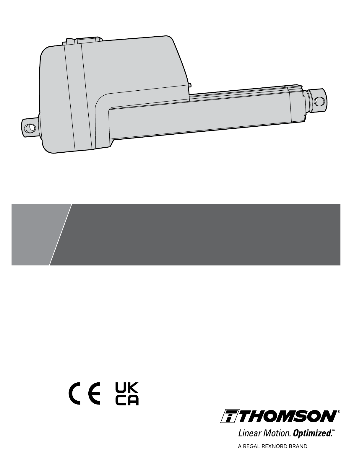
Electric Linear Actuator Electrak XD
(all model types included)
Manufactured by
Thomson Linear LLC, 1300 North State Street, Marengo Illinois 60152, USA
With the following directive
- S.I. 2008/1597 – Supply of Machinery (Safety) Regulations 2008
Used Harmonized Standard(s):
EN ISO 12100:2010 – Safety of Machinery – General Principles for Design - Risk
Assessment and Risk Reduction
And further directive(s)
- S.I. 2016/1091 – The Electromagnetic Compatibility Regulations 2016
Used Harmonized Standard(s):
EN 12895:2015+A1:2019 – Electromagnetic compatibility (EMC) – Industrial
Trucks, emissions replaced with the additional included standard
EN 61000-6-4:2018 – Electromagnetic compatibility (EMC) – Generic standards –
Emission standard for industrial environments
- S.I. 2012/3032 – The Restriction of the Use of Certain Hazardous Substances in
Electrical and Electronic Equipment Regulations 2012
- S.I. 2013/3113 – The Waste Electrical and Electronic Equipment Regulations 2013
Year of first Declaration: 2023
Safety depends upon installing and configuring the linear actuator per the manufacturer’s recommendations. The
machine in which this product is to be installed must conform to the provisions of the EMC directive S.I.
2016/1091. The installer is responsible for ensuring that the end product complies with the EMI requirements and
all the relevant laws in the country where the equipment is installed.
Issued by: Product Line Manager
Mr. Håkan Persson
Kristianstad, 2023-05-05
Signature
Responsible person for technical documentation:
Mr. Peter Gnebner, Tollo Linear AB, Estridsväg 10, SE-291 65 Kristianstad, Sweden
Doc. No: 110813
Tollo Linear AB • Estridsväg 10 • SE-291 65 Kristianstad • Sweden • T +46(0)44–246700 • F +46(0)44–244085
Tollo Linear AB • Box 9053 • SE-291 09 Kristianstad • Sweden • www.thomsonlinear.com
Org. Nr.: 556583-9098 • VAT No. : SE556583-9098-01 • Bg 633-5897 • S.W.I.F.T.: DABASESX • Account No. : SE3412000000013070101488 (Danske Bank)
Declaration of Conformity
of partially completed machinery
We, the company
Tollo Linear AB, Estridsväg 10, SE-291 65 Kristianstad, Sweden
Hereby in sole responsibility declare the conformity of the product series
Electric Linear Actuator Electrak XD
(all model types included)
Manufactured by
Thomson Linear LLC, 1300 North State Street, Marengo Illinois 60152, USA
With the following directive
- EC-Directive 2006/42/EC – Machine Directive (MD)
Used Harmonized Standard(s):
EN ISO 12100:2010 – Safety of Machinery – General Principles for Design - Risk
Assessment and Risk Reduction
And further directive(s)
- EC-Directive 2014/30/EU – Electromagnetic Compatibility Directive (EMCD)
Used Harmonized Standard(s):
EN 12895:2015+A1:2019 – Electromagnetic compatibility (EMC) – Industrial
Trucks, emissions replaced with the additional included standard
EN 61000-6-4:2018 – Electromagnetic compatibility (EMC) – Generic standards –
Emission standard for industrial environments
- EC-Directive 2011/65/EU with amendment 2015/863/EU – Restriction of Hazardous
Substances in Electrical and Electronic Equipment (RoHS2 & RoHS3)
- EC-Directive 2012/19/EU – Waste Electrical and Electronic Equipment (WEEE)
Year of first Declaration: 2023
Safety depends upon installing and configuring the linear actuator per the manufacturer’s recommendations. The
machine in which this product is to be installed must conform to the provisions of the EMC directive 2014/30/EU.
The installer is responsible for ensuring that the end product complies with the EMI requirements and all the
relevant laws in the country where the equipment is installed.
Issued by: Product Line Manager
Mr. Håkan Persson
Kristianstad, 2023-05-05
Signature
Responsible person for technical documentation:
Mr. Peter Gnebner, Tollo Linear AB, Estridsväg 10, SE-291 65 Kristianstad, Sweden
Doc. No: 110913