Revision 1.1.1 ■ 01/02/09 Confidential Page 2 of 4
Introduction
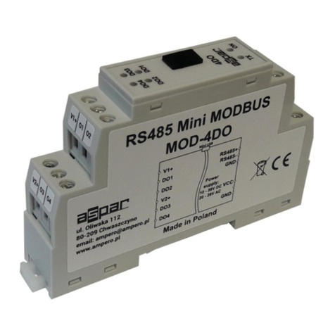
The RWF111HM is a 2-layer FR4 high power module to increase the power and sensitivity of any low
power module operating in 2.4GHz frequency band. It comprises of RF Front End RWF111,
UPG2214 GaAs SPDT switch, 748323024 Wurth Elektronik 2.4GHz BPF, 74LVC2G04 Dual inverter
and two 2-pin relimate male connectors for supply, ground and control.
RWF111HM RF Connections
The RWF111HM can be used as a simple add-on circuit to your existing low power module having any
transceiver operating in 2.4GHz frequency band to improve its range by increasing output power in
transmit mode and sensitivity in receive mode. The RWF111HM consist of two 50 ohm SMA
connectors to connect the RF signal from the radio to RWF111HM connector P1 (on left side) of high
power module. Connect the antenna to connector P2 (on right side) of high power module. Connectors
location can be seen in picture shown below.
To test the performance of the RWF111HM in transmit mode, connect a signal generator to P1 and a
spectrum analyzer to P2. To test the performance of RWF111HM in receive mode reverse the
connections.
The RWF111HM contains two 2 –pin relimate male connectors named as P3 and P4. This can be
used to control and power the RWF111 and UPG2214 GaAs SPDT switch respectively.
Transmit Mode
To check the module in transmit mode apply 2 volts (greater than 0.7Vcc) at P3 and 3 volts (2.9 –4.5
volts) at P4 connector. This will turn-on on the PA of RWF111, corresponding SPDT switch arm and
enable the module in transmit mode.
Receive Mode
To check the module in receive mode apply 0.9 volts (lower than 0.3Vcc) at P3 and 3 volts (2.9 –4.5
volts) at P4 connector. This will turn on the LNA of RWF111, corresponding SPDT switch arm and
enable the module in receive mode.
