manuals.online logo
Brands
  1. Home
  2. •
  3. Brands
  4. •
  5. DITEC
  6. •
  7. Control Unit
  8. •
  9. DITEC DAS200T User manual

DITEC DAS200T User manual

Other manuals for DAS200T

2

Other DITEC Control Unit manuals

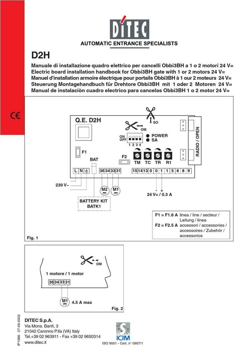
DITEC D2H User manual

DITEC

DITEC D2H User manual

DITEC 192C System manual

DITEC

DITEC 192C System manual

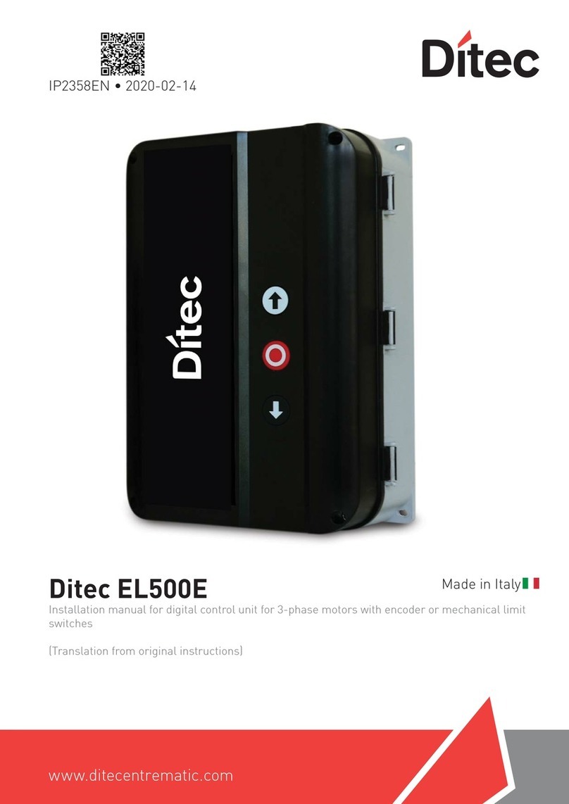
DITEC EL500E Operating and installation instructions

DITEC

DITEC EL500E Operating and installation instructions

Popular Control Unit manuals by other brands

Seitz 14A80 user manual

Seitz

Seitz 14A80 user manual

Wilo RS485 Installation and operating instructions

Wilo

Wilo RS485 Installation and operating instructions

Becker CentralControl CC41 Commissioning Instruction

Becker

Becker CentralControl CC41 Commissioning Instruction

SICK CDB650 operating instructions

SICK

SICK CDB650 operating instructions

Panduit NetKey NKP5E88M Series installation instructions

Panduit

Panduit NetKey NKP5E88M Series installation instructions

MX Options Concentric Petite Fitting instructions

MX

MX Options Concentric Petite Fitting instructions

Clean Water Systems Fleck 2510 Installation & start?up guide

Clean Water Systems

Clean Water Systems Fleck 2510 Installation & start?up guide

Fairchild FSB44104A user guide

Fairchild

Fairchild FSB44104A user guide

LEGRAND Wattstopper LMIN-104 installation instructions

LEGRAND

LEGRAND Wattstopper LMIN-104 installation instructions

PMK ATT10BNCS instruction manual

PMK

PMK ATT10BNCS instruction manual

Tektronix TDS3FFT user manual

Tektronix

Tektronix TDS3FFT user manual

Woodward easYgen Technical manual

Woodward

Woodward easYgen Technical manual

Balluff BNI EIP-502-105-R015 user guide

Balluff

Balluff BNI EIP-502-105-R015 user guide

NXP Semiconductors TWR-LS1021A Getting started

NXP Semiconductors

NXP Semiconductors TWR-LS1021A Getting started

Advantech PCM-3117 Startup manual

Advantech

Advantech PCM-3117 Startup manual

Danfoss MCO 101 manual

Danfoss

Danfoss MCO 101 manual

Moons' Lin Engineering R701P user manual

Moons'

Moons' Lin Engineering R701P user manual

Aventics RV1 operating instructions

Aventics

Aventics RV1 operating instructions

manuals.online logo
manuals.online logoBrands
  • About & Mission
  • Contact us
  • Privacy Policy
  • Terms and Conditions

Copyright 2025 Manuals.Online. All Rights Reserved.

• Manuale tecnico
• Technical manual
• Manuel technique
• Technisches Handbuch
• Manual técnico
• Manual técnico
https://www.ditecentrematic.com/Entrematic/ditecentrematicCOM/QR/Multilanguages/DAS200T/DitecDAS200T.pdf
• Manuale di assemblaggio
• Assembly handbook
• Manuel pour l’assemblage
• KIT-Anleitung
• Manual de ensamblaje
• Manual de montagem
https://www.ditecentrematic.com/Entrematic/ditecentrematicCOM/QR/Multilanguages/DAS200T/Kit_DAS200T_IP2349.pdf
i
• Per consultare i manuali completi utilizzare i seguenti QR code o digitare i seguenti link:
• To read the complete manuals use the following QR codes or type the following links:
• Pour lire les manuels complets, utilizes le code QR suivant ou tapez les liens suivants:
• Die ausführlichen Anleitungen erhalten Sie als Download über folgende QR-Codes oder Links:
• Para leer los manuales completos, use los siguientes códigos QR o escriba los siguientes enlaces:
• Para ler os manuais completos use os seguintes códigos QR ou digite os seguintes links:
Ditec DAS200T Quick reference
www.ditecentrematic.com
IP2350 • 2020-09-30
• Versione aggiornata di que-
sto manuale
• Last version of this manual
2
IP2350
x 2
8
7
5 6
6
T30 T20
1
2
2
3
4
1T20
3
IP2350
x 2
T30 T20
50 1000 1000 1000
12 13
10
11
13
HM= H-39
80
max 70
19
H
27 2030
6
12
KPAM45
9
3
4
4
IP2350
5
500
max 70
6
12
KPAM45
HM= H-39
max 70
KPAM45
80
19
H
27 2030
6
• Fissare e sbloccare il cover aper-
to come mostrato di seguito.
• Secure and unsecure the open
cover as shown below.
• Attachez et detaches le capot ou-
vert comme indiqué ci-dessous.
• Die Arretierungsklammern der
Antriebshaube nur bei eingehakter
und geöffneter Antriebshaube
montieren / demontieren.
• Fije y libere el cobertor abierto
del modo que se indica abajo.
• Fixe e remova a tampa aberta
como é mostrado abaixo.
5
IP2350
7
D
C
B
B
A
B
A
A
+/- 8
+/- 19
10
13
CB
10
D
0,5
8
60 (100*)
SS
60 (100*)
60 60
6060
Barra filettata
Threaded bar
Barre filetée
Gewindestange
Barra roscada
Barra rosquesda
= LM -350
LM LM
LM-383LM-383
60 (100*) 100 (115 DAS200TRF)
S
60
Barra filettata
Threaded bar
Barre filetée
Gewindestange
Barra roscada
Barra rosquesda
= LM -350
LM
LM-383
*Se
*If
*Si
*Ob
*Si
*Se
DAS200TRG
DAS200T
DAS200TRF
60 60(100*)
S
60
LM
Barra filettata
Threaded bar
Barre filetée
Gewindestange
Barra roscada
Barra rosquesda
= LM -350
LM-383
6
IP2350
10
9
BA
C
• Per regolare il sormonto “S” delle ante operare come segue
- Portare le ante in battuta in posizione di chiusura.
- Allentare [A] e spostare l’anta aumentando o diminuendo il sormonto “S”. Stringere A.
Per regolare la tensione della cinghia allentare (B) e agire sul registro [C].
• Proceed as follows to adjust the overlap “S” of the door wings:
- Place the door in the closed position.
- Loosen [A] and move the door wing, increasing or decreasing the overlap “S”. Tighten A.
To adjust the belt tension loosen (B) and act on register [C].
• Pour régler le chevauchement “S” des vantaux :
- Mettre les vantaux en butée en position de fermeture.
- Desserrer [A] et enlever le vantail en augmentant ou en diminuant le chevauchement “S”. Serrer A.
Pour régler la tension de la courroie, desserrez (B) et agissez sur le registre [C].
• Um die Überlappung “S” der Flügel einzustellen, wie folgt vorgehen:
- Die Flügel in die geschlossene Position bringen.
- [A] lockern und den Flügel verschieben und dabei die Überlappung “S”erhöhen oder verringern. A anziehen.
Zum Einstellen der Riemenspannung (B) lösen und mit Schraube (C) einstellen.
• Para regular la sobreposición “S” de las hojas, proceder como sigue:
- Llevar las hojas hasta el tope, en posición de cierre.
- Aflojar (A) y desplazar lahoja aumentando o disminuyendo la superposición “S”. Apretar A.
Para ajustar la tensión de la correa, afloje (B) y actúe en el registro [C]
• Para regular a sobreposição “S” das portinholas, operar da seguinte forma:
- Levar as portinholas em batida para a posição de fecho.
- Afrouxar (A) e deslocar a portinhola, aumentando ou diminuendo a sobreposição “S”. Apertar A.
Para ajustar a tensão da correia, afrouxe (B) e atue no registro [C]
7
IP2350
≥18
12
11 LT≤3000 = 2mm
LT> 3000 = 3 mm
1
12
6
6
5
5
4
24
4
5
2
T20
10
3
10
• Posizionamento sensore sul cover
• Sensor positioning on the cover
• Positionnement du capteur sur le capot
• Sensorpositionierung auf der Antriebshaube
• Posicionamiento del sensor en la tapa
• Posicionamento do sensor na capa
8
IP2350
13
• Ponticellare i contatti N.C. se non utilizzati.
• Jumper the unused N.C. contact.
• Placer un pontet sur tous les contacts N.C. s’ils ne sont pas utilisés.
• NC-Kontakte der Sicherheiten (Anwesenheitssensoren und STOP) überbrücken, wenn sie nicht benutzt werden.
• Puentear los contactos N.C. que no se utilizan.
• Ligar em ponte os contactos N.F. não usados.
• Quadro elettrico
• Control panel
• Tableau électronique
• Elektronische Steuerung
• Cuadro electronico
• Quadro eletronico
IT FR DE ES PT
20 NON USARE NE PAS UTILIZER NICHT VERWENDEN NO SE DEBE UTILIZAR NÃO USAR
19 Blocco
(bobina principale)
Verrouillage
(bobine principale)
Verriegelung
(Hauptspule)
Dispositivo de bloqueo
(bobina principal)
Bloqueio
(bobina principal)
18
16 Apertura lato interno Impulsion intérieure Öffnungsimpulsgeber
Innen Apertura lado interior Apertura do lado interno
13 Test sensore di presenza
centrale
Sourveillance d’impulsio-
ne de présence
Test Anwesenheitssenso-
ren Hauptschließkante
Supervisión de impulso de
presencia central
Monitorização do impulso
de presença central
12 Apertura a chiave Impulsion contact à clef Schlüsselbefehl AUF Apertura con llave Abertura à chave
11 Sensore di presenza
centrale 2
Impulsion de présence
central 2
Anwesenheitssensor 2
Hauptschließkante
Sensor de presencia
central 2
Sensor de presença
central 2
10 Monitoraggio impulso
interno (movimento)
Surveillance d’impulsion
intérieure (mouvement)
Überwachung Bewe-
gungsmelder Innenseite (
Öffnungsimpuls )
Supervisión de impulso
interior (movimento)
Monitorização do impulso
interior (movimento)
9
Sensore di presenza
centrale 1 (usare questo
contatto se utilizzato solo
un sensore)
Impulsion de présence
central 1 ( si un seul
détecteur est utilisé, doit
être connecté ici)
Anwesenheitssensor 1
Hauptschließkante (im-
mer verwenden wenn nur
1 Anwesenheitssensor
angeschlossen wird)
Sensor de presencia cen-
tral 1 (utilice este contacto
si se utiliza solamente un
sensor)
Sensor de presença cen-
tral 1 (usar este contacto
se è usado apenas um
sensor)
6Test sensore di presenza
laterale
Sourveillance de présence
latérale
Test Anwesenheitssenso-
ren Nebenschließkanten
Test sensor de presencia
lateral
Monitorização do impulso
de presença lateral
5Apertura lato esterno Impulsion extérieure Öffnungsimpulsgeber
Außenseite Apertura lado exterior Apertura do lado externo
4Sensore di presenza
laterale 2
Impulsion de présence
latérale 2
Anwesenheitssensor 2
Nebenschließkante
Sensor de presencia
lateral 2
Sensor de presença
lateral 2
3Stop Impulsion d’arrêt Stop Parada Paragem
2
Sensore di presenza
laterale 1 ( usare questo
contatto se utilizzato solo
un sensore)
Impulsion de présence
latérale 1 ( si un seul
détecteur est utilisé, doit
être connecté ici)
Anwesenheitssensor 1
Nebenschließkante (im-
mer verwenden wenn nur
1 Anwesenheitssensor
angeschlossen wird)
Sensor de presencia late-
ral 1 (utilice este contacto
si se utiliza solamente un
sensor)
Sensor de presença late-
ral 1 (usar este contacto
se è usado apenas um
sensor)
DO NOT USE
Central presence sensor test
Inner impulse (motion) monitoring
Side presence sensor test
Side presence sensor 2
Stop
Side presence sensor 1
Blocking device
Blocking device
(+) 24V
Inner side opening
(-) 0V
(+) 24V
Key opening
Central presence sensor 2
Central presence sensor 1
(-) 0V
(+) 24V
Outer side opening
(-) 0V
blocking device connection
(main coil)
}
7
6
5
4
3
2
1
14
13
12
11
10
9
8
17
16
15
20
19
18
(use this contact if used only one sensor)
9
IP2350
IT - Avviamento
Prima di effettuare qualsiasi operazione assicurarsi che l’automazione non sia alimentata e che le batterie siano scollegate.
Quando si installa l’automatismo procedere all’avvio e alla regolazione nel seguente ordine:
1. Collegare gli accessori, sensori di apertura e sicurezza, blocchi, batterie e selettore.
2. Ponticellare i contati di sicurezza 1-2, 1-3, 1-4, 8-9, 8-11 sul quadro elettrico e 1-5 sul modulo plus DAS902MP, se non utilizzati.
3. Collegare l’alimentazione di rete all’automazione.
4. Impostare i seguenti parametri:
Parametro Descrizione Impostazioni
05 Selezione tipo blocco (sul qua-
dro principale di comando)
NOTA: Selezionare SOLO se installato blocco bistabile DAS802LOKB = 12 .
10= nessun blocco
11= blocco antipanico (LDP)
12= blocco standard (LD) e bistabile (LDB)
06 Sblocco
00= Disabilitato
01= Abilitato
Su DAS200TRF impostare 01 .
Se si seleziona manualmente il tipo di blocco ( parametro 5) impostare 01 .
09 Test sensori di presenza
centrale
00= nessun sensore da monitorare installato (impostazione di fabbrica)
01= sensore di presenza 1 (impostare, se installato, un sensore di presenza da monitorare)
02= sensore di presenza 1 e 2 (impostare, se installati, due sensori di presenza da monitorare)
12 Selezione senso di apertura
00= anta singola apre destra
01= anta singola apre a sinistra o due ante (impostazione di fabbrica)
NOTA: DAS200TRG questo parametro non è selezionabile, il senso di apertura si definisce con la
posizione delle staffa attacco cinghia.
16 Monitoraggio impulso interno
(movimento)
Secondo EN16005 o DIN18650 , è necessario monitorare gli impulsi interni = 01 per le vie di fuga.
00= disabilita il monitoraggio
01= abilita il monitoraggio
NOTA: su DAS200TRF impostare 01 .
NOTA: su DAS200TRG questo parametro è impostato a 01 .
29 Test sensori di presenza
laterale
00= nessun sensore da monitorare installato (impostazione di fabbrica)
01= sensore di presenza 1 (impostare, se installato, un sensore di presenza da monitorare)
02= sensore di presenza 1 e 2 (impostare, se installati, due sensori di presenza da monitorare)
67 Selezione tipo automazione 00= automazione ad 1 anta .
01= automazione a 2 ante .
98 Configurazione blocco contatto
16-17 DAS902MP
Selezionare SOLO se installato blocco bistabile DAS802LOKB.
11= blocco bistabile
99 Funzione contatto 6 DAS902MP
00= disattivato
01= disabilita modalià Sostenibile
02= abilitazione del selettore di funzionamento con una chiave (solo COM500ER)
B1
Blocco del selettore (per
COM500ES, COM501ES/ER,
COM502ES/ER)
00= nessun codice di accesso ( non usare per vie di fuga)
01= premere per 2s (non usare per vie di fuga)
02=
codice di accesso, possibile uso con COM500ES (non usare per vie di fuga), COM501ES, COM502ES
03= chiave (da utilizzare con COM501ER /COM502ER)
i
NOTA: per DAS200TRF seguire la procedura di avviamento indicata nel manuale kit DAS200RFKA - IP2351.
i
NOTA: il parametro 10, (Monitoraggio unità di emergenza) su DAS200TRG è impostato su 02= monitoraggio ridondante.
NOTA: se utlizzata batteria 12V,impostare parametro 43=05.
Accesso ApprendimentoMMI Leggere AccessoMMI Scrivere Accesso
Se si utilizza il Configuration Tool CT, disabilitare “l’accesso apprendimento”:
5. Socchiudere il carter e, se presenti dei sensori di sicurezza, verificare che siano
in modalità standby e che non ci siano persone o oggetti in movimento nell’area di
rilevamento dei sensori.
6. Premere il tasto LEARN per 2 secondi, il display lampeggia .
Per consentire la corretta acquisizione della corsa e del peso delle ante, l’ac-
quisizione deve essere effettuata con le ante installate.
7. Liberare l’area di azione dei sensori affinchè vengano rilevati e monitorati durante la
fase di acquisizione.
8. L’automazione effettua delle manovre di apertura e chiusura.
Al termine del ciclo di apprendimento, la porta rimane chiusa e il display indica .
Se non è stato possibile configurare automaticamente alcuni parametri durante il ciclo di
apprendimento, la porta si apre. Il display visualizza dapprima una , quindi il parametro
che non è stato possibile acquisire automaticamente, ad es. se la porta è 2 ante o ad 1 anta (parametro 67).
1. Premere il pulsante SELECT per iniziare a modificare i parametri.
2. Premere nuovamente SELECT per visualizzare il valore del paramentro in modalità lampeggiante.
3. Con i pulsanti UP e DOWN, selezionare il valore corretto.
4. Premere SELECT per confermare e programmare il valore selezionato.
10
IP2350
Before performing any type of operation, make sure that the automation is turned off and the batteries are disconnected.
Start-up and adjustment must be performed in the following order when the automation is installed:
1. Connect the accessories, opening and safety sensors, blocking device, batteries and selector.
2. Jumper the safety contacts 1-2, 1-3, 1-4, 8-9, 8-11 on the control panel and 1-5 on plus module DAS902MP, if not used.
3. Connect the mains power supply to the automation.
4. Set the following parameters:
Parameter Description Settings
05 Lock configuration
(main control unit)
NOTE: Set ONLY if installed bistable lock DAS802LOKB = 12 .
10= No lock
11= Antipanic lock (LDP)
12= Standard lock (LD) and bi-stable lock (LDB)
06 Lock release
00= Off
01= On
On DAS200TRF set 01 .
If lock type is set manually (parameter 5), set 01 .
09 Central presence
sensor test
00= None (factory setting)
01= Presence sensor 1 (set if a presence sensor with monitoring is installed)
02= Presence sensor 1 and 2 (set if two presence sensors with monitoring are installed)
12 Selection of opening
direction
00= Right hand opening for single door wing automation
01= Left hand opening for single door wing automation and for double door automation (factory setting)
NOTE: On DAS200TRG this parameter cannot be set, the opening direction is defined with the position of
the belt attachment bracket.
16 Inner Impulse (motion)
Monitoring
According to EN16005 or DIN18650 it is a demand to have Inner impulse monitoring = 01 escape routes.
00= Disables monitoring
01= Enables monitoring
NOTE: on DAS200TRF set to 01 .
NOTE: on DAS200TRG this parameter is set to 01 .
29 Side presence sensor test
00 = None (factory setting)
01= Presence sensor 1 (set if a presence sensor with monitoring is installed)
02= Presence sensor 1 and 2 (set if two presence sensors with monitoring are installed)
67 Selection of the type of
automation 00= Automation with one door wing
01= Automation with two door wings
98 Lock Configuration, ter-
minal 16-17 DAS902MP
Set ONLY if installed bistable lock DAS802LOKB.
11= Bistable lock
99 Function Select, terminal
6 - DAS902MP
00= No function
01= Disables Sustainable drive mode
02= Enable the Mode Selector with a key (only COM500ER)
B1
Operation mode selector
key lock (for COM500ES,
COM501ES/ER,
COM502ES/ER)
00= No access code ( do not use for escape route)
01= Hold for two sec.( do not use for escape route)
02= Passcode, possible use with COM500ES (do not use for escape route), COM501ES, COM502ES
03= Key (to use with COM501ER /COM502ER)
EN - Start up
5. Continuare a configurare gli altri parametri non ancora appresi.
6. Premere LEARN/EXIT per più di 2 secondi e il display visualizza , dopo 2 secondi la porta si chiude ed è pronta per il funzionamento.
Se necessario, si possono regolare i seguenti parametri principali:
Parametro Descrizione Impostazioni
00 Selezione velocità di apertura (cm/s) 10÷70cm/s
02 Selezione velocità di chiusura (cm/s) 10÷70cm/s
03 Selezione tempo chiusura automatica (00÷60s)
11 Apertura parziale (00-99%)
15 Programma della corsa (01÷05)
Regolazione delle prestazioni. Imposta la velocità con la quale la porta accelera o frena.
01= Uniforme, per ante leggere
05= Prestazioni massime, per ante pesanti
38 Selezione funzionamento in continuità
con batteria 24V, DAS902BAT2 (00÷01)
00= Disabilitato
01= Abilitato
NOTA: su DAS200TRG il parametro non è visibile ed è impostato a 00.
49 Forza massima di apertura
(02÷23N x 10)
Se la manovra di riapertura avviene troppo bruscamente, impostare il parametro 49 con un
valore più basso del valore di fabbrica (10), ad esempio 04 - 05.
Terminato l’avviamento chiudere il cover e fissarlo con le apposite viti.
i
NOTE: for DAS200TRF follow the start up procedure indicated in the DAS200RFKA manual kit - IP2351.
i
NOTE: the parameter 10, ( Emergency Unit Monitoring) on DAS200TRG is set to 02= Redundant monitoring.
NOTE: If the 12V battery is used set parameter 43=05.
Learn AccessMMI Read accessMMI Write access
If the CT Configuration Tool is used, disable the “Learn access”: