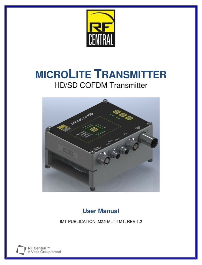
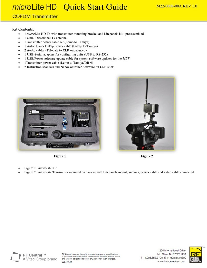
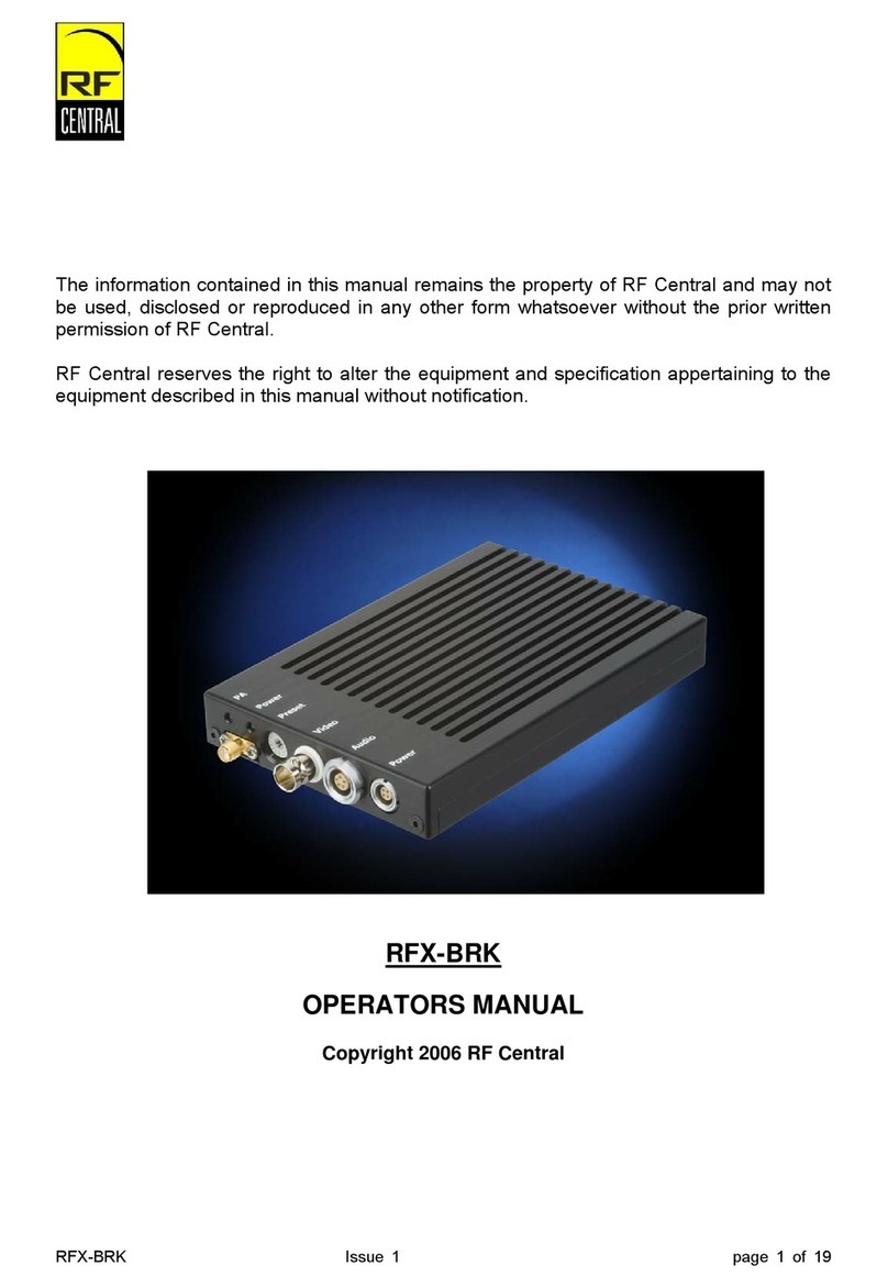
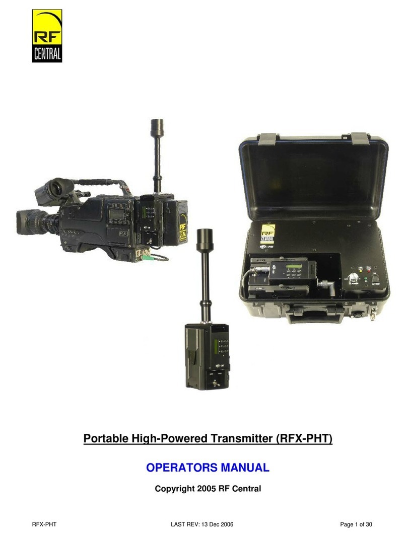
RF Central RFX-NLL User manual

NON-LICENSED LINK (RFX-NLL)
OPERATORS MANUAL
Copyright 2006 RF Central
RFX-NLL Issue 2.0 page 1 of 20

CONTENTS
1GENERAL SAFETY INFORMATION..............................................................................................3
1.1 Health & Safety.......................................................................................................................4
1.2 Maximum RF Power Density Limits ........................................................................................5
2INTRODUCTION.............................................................................................................................6
3APPLICATIONS..............................................................................................................................7
4FEATURES OF THE RFX-NLL.......................................................................................................8
5BEFORE USING THE RFX-NLL.....................................................................................................9
6SAFETY INSTRUCTIONS............................................................................................................10
7USING THE RFX-NLL...................................................................................................................11
8SETUP..........................................................................................................................................12
8.1 RECEIVER:...........................................................................................................................12
8.2 TRANSMITTER:....................................................................................................................14
8.3 SYSTEM STATUS INDICATOR............................................................................................16
9FREQUENTLY ASKED QUESTIONS...........................................................................................17
10 CONTACT INFORMATION.......................................................................................................19
11 Appendix A - SPECIFICATIONS...............................................................................................20
11.1 Video.....................................................................................................................................20
11.2 RF Information ......................................................................................................................20
11.3 Other.....................................................................................................................................20
The information contained in this manual is the property of RF Central and may not be used, disclosed, or reproduced in any
other form without the prior written permission of RF Central.
RF Central reserves the right to alter the equipment and specification appertaining to the equipment described in this manual
without notification.
RFX-NLL Issue 2.0 page 2 of 20

1 GENERAL SAFETY INFORMATION
The information that follows, together with local site regulations, should be studied by
personnel concerned with the operation or maintenance of the equipment, to ensure
awareness of potential hazards.
WARNING- RF Power Hazard: High levels of RF power are present in the unit. Exposure to RF or
microwave power can cause burns and may be harmful to health.
Switch off supplies before removing covers or disconnecting any RF cables, and before inspecting
damaged cables or antennas.
Avoid standing in front of high gain antennas (such as a dish) and never look into the open end of a
waveguide or cable where RF power may be present.
Users are strongly recommended to return any equipment that requires RF servicing to RF Central.
WARNING- GaAs / BeO Hazard: Certain components inside the equipment contain Gallium Arsenide
and Beryllium Oxide that are toxic substances. Whilst safe to handle under normal circumstances,
individual components must not be cut, broken apart, incinerated, or chemically processed. In the
case of Beryllium Oxide, a white ceramic material, the principal hazard is from the dust or fumes which
are carcinogenic if ingested, inhaled, or entering damaged skin.
Please consult your local authority before disposing of these components.
CAUTION - Tantalum Capacitors: When subjected to reverse or excess forward voltage, ripple
current or temperature these components may rupture and could potentially cause personal injury.
CAUTION: This system contains MOS devices. Electro-Static Discharge (ESD) precautions should be
employed to prevent accidental damage.
RFX-NLL Issue 2.0 page 3 of 20

1.1 Health & Safety
Exposure to Non-Ionizing (RF) Radiation/Safe Working Distances
The safe working distance from a transmitting antenna may be calculated from the relationship:
D = √ PT. GR
4π.w
In which D = safe working distance (meters)
PT = transmitter or combiner power output (watts)
GR = antenna gain ratio = anti log (gain dBi ÷10)
w = power density (watts/square meter)
The RF power density value is determined by reference to safety guidelines for exposure of the
human body to non-ionizing radiation. It is important to note that the guidelines adopted differ
throughout the world and are from time-to-time re-issued with revised guidelines. For RF Central use,
a maximum power density limit of 1w/m² is to be applied when calculating minimum safe working
distances.
Important Note: It must be remembered that any transmitting equipment radiating power at
frequencies of 100 kHz and higher, has the potential to produce thermal and athermal effects upon the
human body.
To be safe:
a) Operators should not stand or walk in front of any antenna, nor should they allow anyone else
to do so.
b) Operators should not operate any RF transmitter or power amplifier with any of its covers
removed, nor should they allow anyone else to do so.
Worked examples
Antenna Transmitter Power
Type Gain (dBi) Gain Ratio 2W 4W 10W 30W
OMNI 4 2.5 1 1 1.5 2.5
HELIX 20 100 4 5.6 9 15.5
PARABOLIC
DISH 35 3,162 22.5 32 50 87
MINIMUM SAFE DISTANCE (METERS)
RFX-NLL Issue 2.0 page 4 of 20

1.2 Maximum RF Power Density Limits
The RF Radiation Power Density limit figure recommended by RF Central is based upon guideline
levels published in:
a. IEEE standard C95.1 1999 - IEEE Standard for Safety Levels with respect to Human Exposure
to Radio Frequency Electromagnetic Fields, 3 kHz to 300 GHz.
b. Guidelines for Limiting Exposure to Time-varying Electric, Magnetic & Electromagnetic Fields
(up to 300 GHz) published in 1998 by the Secretariat of the International Commission on Non-Ionizing
Radiation Protection (ICNIRP).
Both documents define guideline RF power density limits for "Controlled" and "Uncontrolled"
environments. An uncontrolled environment is defined as one in which the person subjected to the RF
radiation may be unaware of and has no control over the radiation energy received. The uncontrolled
environment conditions can arise, even in the best-regulated operations and for this reason the limits
defined for the uncontrolled environment have been assumed for the RF Central recommended limit.
Documents a) and b) also show the RF power density guidelines to be frequency dependent. Different
power density / frequency characteristics are presented in the two documents. To avoid complexity
and to avoid areas of uncertainty, RF Central recommends the use of a single power density limit
across the frequency range 100 kHz to 300 GHz. The 1w/m² power density limit we recommend
satisfies the most stringent of the guidelines published to date.
Footnote: The IICNIRP document may be freely downloaded from the internet at
www.icnirp.de/documents/emfgdl.pdf (PDF file).
Issue Status
Issue Date Changes
Issue 1.0 November 2005 First Issue
Issue 1.1 May 2006 Update
Issue 2.0 December 2006 Update: New Model
RFX-NLL Issue 2.0 page 5 of 20

2 INTRODUCTION
Welcome to the world of digital microwave technology with the RFX-NLL. This guide will help
you make the most of this revolutionary technology that is so simple to set-up and operate
you will wonder how you ever did without it.
The RFX-NLL wireless technology provides a fully digital microwave link from any camera
clearly without ghosting, break-up, or interference at a fraction of the cost of COFDM
systems.
This groundbreaking technology has been specifically designed for the needs of ENG, OB,
portable field monitoring or video-assist applications.
Unlike analog technology, the RFX-NLL allows multiple channels to operate legally in license
exempt bands.
Stable MPEG2 video and two channels of audio can be transmitted from a roaming camera
for live to air transmission, viewed on a traditional monitor or downloaded to a laptop for
immediate reference.
The RFX-NLL is engineered for single or multi-camera platforms with composite video, and
can be specifically tailored for each and every production.
RFX-NLL Issue 2.0 page 6 of 20

3 APPLICATIONS
Now everyone can be part of the digital revolution. Whether you are filming a feature film,
documentary, or live sporting event, the RFX-NLL delivers reliability every time, at a fraction
of the cost you’d expect.
• ENG live-to-air roaming camera link
• Multi-camera production
• Digital replacement for analog video assist
• Reality TV and portable field monitoring
• Sporting arena and events filming
• Monitor and record fixed point or body worn surveillance cameras
• Instantly record and review stored footage using HDD recorders.
RFX-NLL Issue 2.0 page 7 of 20

4 FEATURES OF THE RFX-NLL
• Simple to set-up and operate
Simply plug in video, audio and power cables.
• License exempt
• No break-up, noise or interference
The RFX-NLL far exceeds any analog microwave system with superior video and
audio quality, and a revolutionary diversity antenna receiving system that reduces
interference and break-up even further.
• Diversity antenna receiving system
The RFX-NLL integrates a revolutionary diversity antenna system that minimizes multi-
path and dramatically increases picture stability.
• Secure transmission with point-to-point encryption
Traditional analog UHF and 2.4 GHz transmission can be easily tapped into and
recorded by unauthorized persons, risking piracy. The RFX-NLL provides secure
transmission at all times with pre-shared key encryption.
• Auto channel select
Unit auto selects the clearest of multiple channels within the frequency band.
• MPEG-2 compression
The RFX-NLL uses MPEG-2 technology to ensure full SD quality, with resolution at full
frame rate (480 lines interlaced)
• Two channels of analog audio
The RFX-NLL has 2 channels of CD quality audio that can be used for stereo audio
feeds live to air, camera feeds or a combination of audio and time code.
• Operates without interference to or from Wi-Fi a, b, or g, cordless or mobile telephones and
household appliances
The RFX-NLL automatically scans the entire license exempt frequency band and
selects a clear channel each time you set-up.
RFX-NLL Issue 2.0 page 8 of 20

5 BEFORE USING THE RFX-NLL
Before using the RFX-NLL for the first time, please check the following to ensure the RFX-
NLL hasn’t been damaged during shipping.
1. Visually inspect outer casing, plugs, and cables to ensure there are no breakages.
2. Slowly rotate the RFX-NLL 360 degrees to ensure all components are in place and nothing
is loose inside the casing.
If you require assistance or are concerned about the working condition of the RFX-NLL,
please contact our Technical Support team by telephoning 717-249-4900.
RFX-NLL Issue 2.0 page 9 of 20

6 SAFETY INSTRUCTIONS
Follow these safety precautions when using the RFX-NLL to reduce the risk of damage and
malfunction of the RFX-NLL, other property, and persons.
• Keep all ventilation holes clear and unblocked. Ensure that proper ventilation is provided at
all times when in use.
• Do not insert objects of any kind into the ventilation holes as this may result in damage to
the RFX-NLL.
• Do not use when wet and provide adequate cover when using in the rain.
• Do not use liquid cleaners or aerosol cleaners on the RFX-NLL. Use a damp cloth for
cleaning.
• Do not disassemble this product. If service or repair is required, contact our Technical
Support team by telephoning 717-249-4900.
RFX-NLL Issue 2.0 page 10 of 20

7 USING THE RFX-NLL
The RFX-NLL has been designed to be as compact and light as possible for the operator to
use. The casing of the RFX-NLL is durable and constructed to last, but care should be taken
to avoid damaging the sensitive circuit board inside. Do not attempt to open or service the
RFX-NLL. The internal circuit and antennas are highly tuned and tampering with them will
damage the unit.
Correct choice for antennas and placement is the key to a reliable system. Keeping ‘line of
sight’ as much as possible between the cameraman and the receiver will also increase your
range and reliability.
The RFX-NLL’s unique transmission system is specifically designed to transmit broadcast
quality video through walls and floors from a moving camera. However, all microwave
transmission systems will have their range dramatically reduced when attempting to transmit
through objects such as concrete, steel, glass, water and the human body.
Remember the main rule of thumb is if the ‘GREEN LED’ (link quality indicator) is flashing
slowly, don’t go live.
RFX-NLL Issue 2.0 page 11 of 20

8 SETUP
8.1 RECEIVER:
Mount the receiver on a stand or in a position
where the best ‘line of sight’ to the camera will be
achieved. Walls and floors will dramatically reduce
the range.
Keep the antennas as high as possible to stop
crowds and audiences blocking the signal.
Supply the receiver with
8-18v DC from a battery
or power supply via the 4
pin XLR.
RFX-NLL Issue 2.0 page 12 of 20

RED LED
YELLOW LED
GREEN LED
Once on, the Red LED
indicator will turn on solid
and the Yellow LED
indicator will begin to flash.
HEADPHONE
Plug in the video BNC for composite video.
Plug DB-15 connector power and audio
breakout in.
RFX-NLL Issue 2.0 page 13 of 20

8.2 TRANSMITTER:
Place the transmitter on the
back of the camera.
Screw on antennas and position
so they will bend back if
knocked.
Clip camera battery
on back of
transmitter.
Turn transmitter on.
The LED will turn RED, and the yellow LED will
flash. This indicates that the transmitter is searching
for its paired receiver. This can take up to one
minute in very high interference or congested areas.
Red LED Light
Remote Status
LED Cable
Connector
Once the units are locked, a solid RED, solid
YELLOW, and a GREEN slow-blinking LED will be
displayed. This indicates that the system is working
but there is no video being received by the
transmitter.
RFX-NLL Issue 2.0 page 14 of 20

RFX-NLL Issue 2.0 page 15 of 20
Plug one end of the Video cable into the BNC
connector on the camera, and the other end
into the BNC connector on the transmitter.
Plug DB-15 connector to XLR breakout into
transmitter using a Line Level audio source.
Turn on camera. The GREEN LED will begin
to flash fast.
The faster the flashing GREEN LED the higher quality
link is established.
CAUTION:
If the LED is flashing slowly, this
indicates that the link is not guaranteed.
Move the receiver antennas to a more
suitable location to gain ‘line of sight’. GREEN LED LIGHT
G
HT

RFX-NLL Issue 2.0 page 16 of 20
8.3 SYSTEM STATUS INDICATOR
The following table shows the LED indicators on the RFX-NLL.
LED Status
RED System Power on
YELLOW
flashing Signal survey / searching (this can take up to 1 minute in
the event of heavy RF traffic)
YELLOW Locked on Channel
GREEN flashing Data rate (fastest flash = best data rate flow)*
*Light on more than off
GREEN flashing
(blinking) slowest No video at TX (periodic blink only = no video)*
*Light off more than on
Remote LED Status Cable
RED Communicating
RED flashing Lost Communication
GREEN flashing Higher Data Rate
GREEN
flashing slow Lower Data Rate

RFX-NLL Issue 2.0 page 17 of 20
9 FREQUENTLY ASKED QUESTIONS
Q. What do I do if the picture starts to break up?
A. Turn both the receiver and the transmitter off and on again. This will reset and allow the
RFX-NLL to select a different channel to use.
Q. What if the LED indicators flash yellow?
A. Make sure that the TX and RX are on matching frequency bands (both 5.2 GHz and 5.8
GHz). Check that you are supplying 8 – 18 volts DC to the RFX-NLL. Reduce the distance
and turn the RFX-NLL off and on again. It can take up to 60sec for the TX and RX to lock.
Q. What if the LED indicators are yellow but I am not receiving any video or audio?
A. If the LED indicators are YELLOW with a quick GREEN blink, then the RFX-NLL is
transmitting information and is working correctly. The GREEN slow flashing indicates there is
no video at the TX side or there are weak signal conditions. Check cable connections
between the transmitter and the camera, the monitor and the receiver, or try a closer distance
between the units.
Q. What if I am using the RFX-NLL within recommended distance guidelines and it is
not working properly?
A. Always maintain a line of sight between the transmitter and receiver wherever possible, as
microwave transmission doesn’t work well through walls or structures. Mount the receiver as
high as possible internally or externally with a clear line of sight to the camera for best results.
Solid walls like brick, concrete, steel and insulated walls dramatically reduce the range of the
RFX-NLL.
Q. Does the RFX-NLL interfere with WiFi 802.11 A, B or G?
A. No, because the layers are fundamentally different and the two systems do not
communicate or interfere with one another.
The RFX-NLL automatically scans the frequency spectrum and avoids any other channels
occupied by other networks. When using more than one system within a small area ensure
the distance between the receivers exceeds 15 feet (5 meters), as the receivers could
interfere with one another.

RFX-NLL Issue 2.0 page 18 of 20
Q. What do I do about audio delay if taking a separate audio source to ensure the audio
is in sync with the video?
A. Due to the RFX-NLL’s error-correcting technology you will experience approximately 12
frames of delay. To correct this, simply delay your audio source at the same time as the video
output.
We recommend the BEHRINGER SHARK DSP110:
www.behringer.com/DSP110/index.cfm?lang=ENG
This delay unit will allow you to sync your audio feed with the pictures being transmitted by
the RFX-NLL and is inexpensive and user friendly.
Q. What do I do if I am having audio problems at the receiver?
A. Verify audio in at the headphone jack or check audio connector at the transmitter.
Q. What do I do if the RFX-NLL becomes wet during use?
A. Disconnect power supply immediately. Dry the RFX-NLL with a cloth to remove excess
water and leave to dry completely for 24 hours before attempting to re-use.

RFX-NLL Issue 2.0 page 19 of 20
10 CONTACT INFORMATION
Sales / Rentals / Customer Service Team
Technical Support Team
RF Central, LLC
99 Garden Parkway
Carlisle, PA 17013
USA
717-249-4900 (telephone)
717-249-3630 (fax)
www.rfcentral.com

RFX-NLL Issue 2.0 page 20 of 20
11 Appendix A - SPECIFICATIONS
11.1 Video
Video MPEG-2 SD resolution, full frame rate
Auto select 4 Mb/s, 8 Mb/s, 16 Mb/s
Composite
Standard NTSC / PAL auto select
Audio 2 Channels Analog audio 0 dBm Line Level in
Latency 465 ms (12 frames)
11.2 RF Information
Transmission method OFDM
Range Outdoors over 1000 ft / 350 m line of sight indoors with internal
walls approx 70 ft. / 30 m
Security Pre shared key encryption
Channel select Automatic selection within frequency band (multiple channels)
Frequency 5.2 GHz or 5.8 GHz
Reception sensitivity -76 dBmW typical
11.3 Other
System indicators Signal lock status / data rate / video loss at TX
Unit Weight 14 ½ oz (410g)
Dimensions 6” x 3
7/8” x ¾” (152mm x 98mm x 19mm)
Power 8-18V DC (10.5-38v optional) 0.45amps @12v
Temperature Range -10 to 48 C
Humidity 5% - 85% typical
FCC approved part 15
NOTE:
If using this system outside of the United States, please note that most European Community
countries have restrictions relating to the use of 5.2 GHz, allowing it to be used indoors only. Please
refer to your local authorities guidelines before use.
Table of contents
Other RF Central Transmitter manuals