Minicom 1VS22031 User manual

www.minicom.com
InternationalHQ
Jerusalem,Israel
Tel:+972 2535 9666
minicom@minicom.com
NorthAmericanHQ
Linden,NJ,USA
Tel:+1908 4862100
info.usa@minicom.com
EuropeanHQ
Dübendorf,Switzerland
Tel:+4144 823 8000
info.europe@minicom.com
Customersupport - support@minicom.com
5UM40123 V1.2 2/06
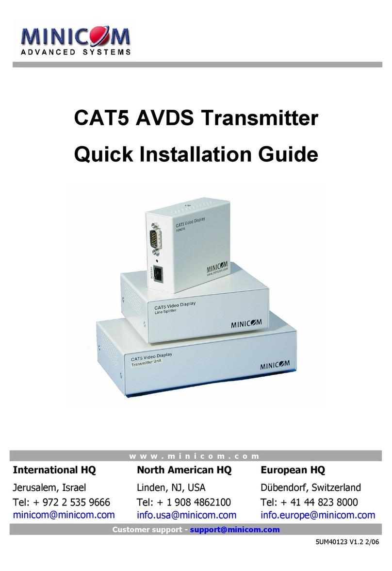
CAT5 AVDS Transmitter
QuickInstallationGuide
All manuals and user guides at all-guides.com
all-guides.com

AVDSTRANSMITTER
1
1. Introduction
TheAVDS TransmittersystemfromMinicom, broadcastsreal-timehigh-resolution
videoand monoaudiosignalstohundredsofremotedisplaymonitorsand speakers.
TheAVDS Transmittersystemconsistsofthefollowingcomponents:
·TransmitterUnitP/N1VS22031+ControlUnit
·LineSplittersP/N1VS22019 toexpand thesystem
·RemoteunitsP/N1VS23011
·PowerRemoteunitsP/N1VS22036–forenhancedaudiosignals
Warning!DoNOTconnectunitswiththeabovepartnumberstounitsof
earlierAVDS Transmittersystemsthathavedifferentpartnumbers. Part
numbersare locatedonthebackofeachunit.
2. The 2typesofRemote units
Note! AnyreferencetoRemoteunitsreferstobothRemoteandPowerRemoteunits
unless statedotherwise
BothtypesofRemoteunitscanbeup to110m/360ftawayfromtheTransmitter.
Thedifferencebetweenthe2Remoteunittypesisasfollows:
TheRemoteunits:
·Donotneeda separatepowersupplytheyreceivepowerfromtheconnected
CAT5FTPcable
·MustbeconnectedwithShieldedCAT5FTP cables
ThePowerRemoteunits:
·Needa separatepowersupply(provided)
·CanbeconnectedwithCAT5UTPorShieldedCAT5FTPcables
·Producebetterqualityaudiosignals
All manuals and user guides at all-guides.com

QUICK INSTALLATIONGUIDE
2
3. The multi-functionalAVDS Transmittersystem
YoucanusetheAVDS Transmittersysteminthefollowingways:
(A)WithouttheControlUnit
TheAVDS Transmittersystemconstantlybroadcastsa computerscreenwith
audiotoall remotemonitors/speakers.
(B)With theControlUnit
·Broadcastacomputerscreenwithaudiotoallremotemonitors/speakers
·Darkenall remotescreens(audiobroadcastisunaffected)
·Releasetheremotescreenstoallowlocalmonitorviewing(whenremote
computersareconnected).
Thescreendarkfunctionisusefulwhencarryingoutmaintenance, changing
thebroadcastprogramorina classroomenvironmenttograbstudents’
attention.
(C)RS232 Serialcontrol
ConnecttheRS232 cable(illustratedbelow)andcontrolthesystemvia RS232
Serialcontrol.
Screen resolutions
Alltheaboveapplicationsbroadcastvideoup toresolutionsof1600 x1200@
75Hzdependingonthecablelength.
4. The AVDS Transmitterunits
ThefiguresbelowillustratetheControlunit, TransmitterUnit, LineSplitterand the
Remoteunits.
VDSControlUnit
Master
toall
Dark
all
MINICOM
Control Unit
All manuals and user guides at all-guides.com

AVDSTRANSMITTER
3
www.minicom.com
Headset
Input
Line
VIDEOIN
VIDEOOUT
SYSTEM
12VDC
BUTTON
Power
connector Control Unit
System
cable Monitor
Video
cable
Audio cables
Microphone &
speakers
Output
SERIAL
C
O
N
T
R
O
L
Serial
TransmitterUnit
www.minicom.com
SYSTEM IN
12VDC
SYSTEM OUT
Systemcables
Power
connector
SystemcablefromTransmitteror
previousLineSplitter
LineSplitter
AUDIO
PICTURE
IN
SYSTEM
VIDEOIN
SideA Side B
System
cable Headphones
Monitor
Video
cable
Sound card
Pictureadjuster
Remoteunit
All manuals and user guides at all-guides.com

QUICK INSTALLATIONGUIDE
4
AUDIO
PICTURE
IN
SYSTEM
VIDEO IN
SideA Side B
System
cableHeadphones
Monitor
Video
cable
Soundcard
Pictureadjuster
6VDC
Power
adapter
PowerRemoteunit
5. Pre-installationinstructions
Note!IntheAVDS TransmittersystemtheCAT5cablescarryelectricalpower.
Thereforedo NOT connectthemtoany otherdevice. Toavoidthiswerecommend
youattachthestickersprovidedtotheendsofeachCAT5cable.
Placecablesawayfromfluorescentlights,airconditioners, and machinesthatare
likelytogenerateelectricalnoise.
6. The AVDS Transmittercables
TheAVDS Transmittercablesareillustratedbelow.
RemoteAudiocable
Transmitter&RemoteVideocable
ToRemotecomputer’s
Microphone port
ToRemotecomputer’s
Speakerport
To
Microphone
connector
ToRemote’sAudioIn
port
To
Computer’s
Video card
To
Transmitter’s
orRemotes’
Video Inport
TransmitterAudiocables
Tohostcomputer’s
Microphone port
Tohostcomputer’sSpeaker
port
ToTransmitter’sLine
Outputport
ToTransmitter’sLine Input
port
Tohost
computer’s
Serialport
ToTransmitter’s
Serialport RS232cable
All manuals and user guides at all-guides.com

AVDSTRANSMITTER
5
7. Connectingan optionalremote computer
YouhavetheoptiontoconnecttheRemoteunitstoa computer, whichcanbe
workedonlocally. TheRemoteVideoandAudiocablesareonlyusedwhenthe
Remoteunitisconnectedtoa computer.
8. Power supply
ConnecttheTransmitterand LineSplitterstothepowersupplywith12 VDC, from
theAC/DCadapterprovided.
ConnectthePowerRemotestothepowersupplywith6VDC, fromtheAC/DC
Poweradapterprovided.
TheRemoteunitsreceive12 VDC, 160 mAvia theCAT5cablesfromtheLine
Splitter.
9. Expandingthe AVDS Transmitter system
YoucanexpandtheAVDS Transmittersystemto512 Remoteunitsbyhavingup
to3levelsofLineSplitters.TheLineSplittersonlevels1and 2canhave8Remote
unitsorLineSplittersconnectedtoit. EachLineSplitteron level3canconnectto8
Remoteunits. (See theconfigurationdiagramonpage6).
All manuals and user guides at all-guides.com
all-guides.com

QUICK INSTALLATIONGUIDE
6
10. The AVDS Transmitterconfigurationfor aCBT application
ThefigurebelowillustratestheAVDS Transmitterconfiguration.
Audio
cable
Videocable
Videocable
TransmitterUnit
Transmitter
computer
Optional remote
computer
Line
Splitter
Optional
ControlUnit
Audio
cable
Videocable
Audio
cable
Videocable
Power/
Remote
Line
Splitter
CAT5cablesto
RemoteDongles
orLineSplitters
Audio cables
CAT5cableto
LineSplitter
Level1
Level2
RS232 cable
CAT5cablesto
Remoteunitsor
LineSplitters
CAT5cablesto
Remoteunitsor
LineSplitters
Power/
Remote
Power/
Remote
Optional remote
computer
Optional remote
computer
All manuals and user guides at all-guides.com

AVDSTRANSMITTER
7
11. AVDS Transmitterdetailedconnections
ThefigurebelowillustratesthedetailedconnectionsoftheAVDS Transmitter
units.
VDSControlUnit
Master
toall
Dark
all
MINICOM
Audio
cable
ww w .minic om .c om
SYSTEMIN
12VDC
SYSTEMOUT
AUDIO
PICTURE
IN
Videocable
Video cable
ControlUnit
CAT5cablesto
Remoteunitsor
Line Splitters
Power/
Remote
unit
Line
Splitter
Transmitter
Unit
Transmitter
computer
Optional
Remote
computer
Microphoneconnector
topinkAudiocable
connector
CAT5cableto
Line Splitter
CAT5cablesto
Remoteunitsor
Line Splitters
Pinkconnectorto
Microphone port
Orange connectorto
speakerport
ToInput port
ToMic.port
ToSpeakerport
Audiocables
ToSerialport
ToUSBport
AVI cable
www.minicom.com
Headset
Input
Line
VIDEOIN
VIDEOOUT
SYSTEM
12VDC
BUTTON
Output
SERIAL
C
O
N
T
R
O
L
ToButton port
To
Serial
port
ToOutput
port
All manuals and user guides at all-guides.com

QUICK INSTALLATIONGUIDE
8
12. Configurationwithoutremotecomputers
ThefigurebelowillustratestheAVDS Transmitterconfigurationwithoutoptional
computersconnectedtotheRemoteunits.Theconnectionsarethesameasabove
minustheRemoteVideoandAudiocables.
Video cable
TransmitterUnit
Transmitter
computer
Line
Splitter
Optional
ControlUnit
Power/
Remote
Line
Splitter
CAT5cablesto
RemoteDongles
orLine Splitters
Audiocables
CAT5cableto
LineSplitter
Level1
Level2
RS232 cable
CAT5cablesto
Remoteunitsor
LineSplitters
CAT5cablesto
Remoteunitsor
Line Splitters
Power/
Remote
Power/
Remote
All manuals and user guides at all-guides.com

AVDSTRANSMITTER
9
13. OperatingtheAVDSTransmitter system
OperatetheAVDS TransmittersystemwiththeControlUnitorRS232Serial
control.
TheControlUnitperformsthefollowingfunctions:
Mastertoall
Press the Mastertoall buttontosendthehostcomputer’sscreenwithaudiotoall
remotescreens/speakers.TheLEDabovethebuttonlightsup.
Press thebuttonagaintoreleasetheremotescreens/speakers,allowinglocalmonitor
viewing(whenremotecomputersareconnected).
Darkall
Press the Darkall buttontodarkenall remotescreens. TheLEDabovethebutton
lightsup. (Darkall doesnotaffectaudiobroadcasting).
Press thebuttonagaintoreleasetheremotescreens.
14. Adjustingthe picture
Whenthebroadcastscreenneedsadjusting, usea smallscrewdrivertoturnthe
PictureadjusterontheRemoteunit.
All manuals and user guides at all-guides.com

QUICK INSTALLATIONGUIDE
10
15. Technicalspecifications
SYSTEM
Resolution Upto 1600x1200@75Hz
SystemcableShieldedCAT5FTP2x4x24AWGSolidWireConductor
cable(+UTPfor PowerRemote)
Maxdistance110m/360ft
Input/OutputVideoSignals Analog signalred,green, blue0.7v p-p75Ohm
Sync. TTLcompatible
Horizontal/VerticalSync.Polarity Positive/Negative
Audio Mono
Operating Temperature 0ºCto40ºC/32ºFto104ºF
StorageTemperature -40ºCto70ºC/-40ºFto158ºF
Warranty 3Years
TRANSMITTER LINESPLITTER REMOTE
Cables&
Connectors
VGAIn- HDD15M
VGAOut - HDD15F
SystemOut - RJ45
Mic/Headphone/ScIn/Out –
Jack
Controller - MiniDin8F
Power jack
SystemIn- RJ45
SystemOut - RJ45
Power jack
SystemIn- RJ45
CPUVGA- HDD15M
Screen - HDD15F
AudioIn/Out –Jack
Power Remote-
Power jack
Dimensions
(HxWxD)
4.2x15x9.4cm/
1.6x5.9x3.7in
4.2x11.8x9.6cm/
1.4x3.9x3.1in
3.2x7.8x6.2cm/
1.3x3.1x2.4”
Powersupply AC/DC PowerAdapter
12VDC 2A
AC/DC PowerAdapter
12VDC 2A
Remote
12 VDC, 160mA
fromBroadcasteror
LineSplitter
Power Remote-
AC/DC Power
Adapter6VDC 2A
All manuals and user guides at all-guides.com
all-guides.com

AVDSTRANSMITTER
11
RegionalOffices
Germany
Kiel
Tel:+49431 668 7933
info.germany@minicom.com
France
Vincennes
Tel:+33149 57 00 00
info.france@minicom.com
Italy
Rome
Tel:+3906 8209 7902
info.italy@minicom.com
www.minicom.com
2006 ©CopyrightMinicomAdvancedSystemsLtd.
All manuals and user guides at all-guides.com
Other manuals for 1VS22031
1
This manual suits for next models
3
Table of contents
Other Minicom Transmitter manuals
Popular Transmitter manuals by other brands

Audio Technica
Audio Technica ESW-T212 Installation and operation

Belkin
Belkin F8V3080 - TuneCast II Mobile Transmitter user guide

YOKOGAWA
YOKOGAWA DpharpEJX vigilantplant EJX110 user manual

Questtel
Questtel L-RF-2mW-TX user manual

Alula
Alula RE222 NanoMax instructions

Interlogix
Interlogix VT7820 Installation & operation instructions