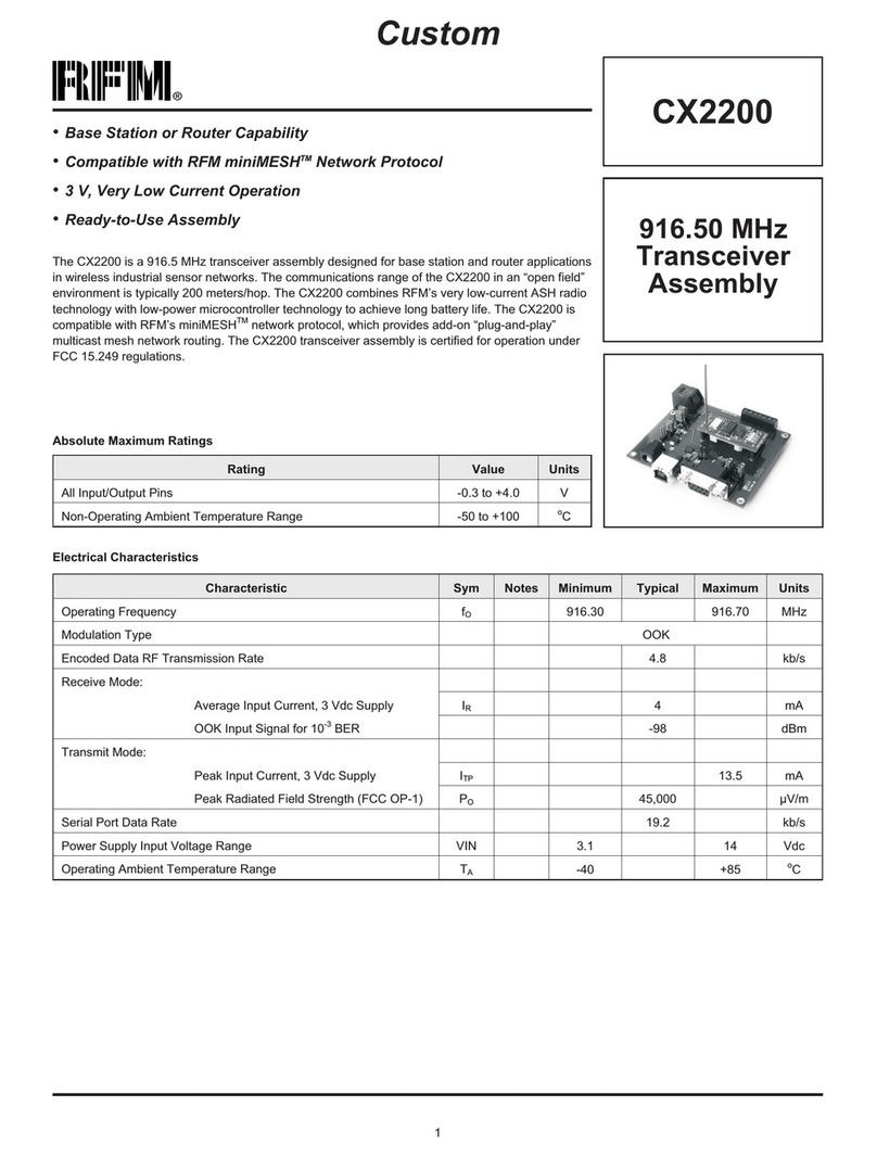
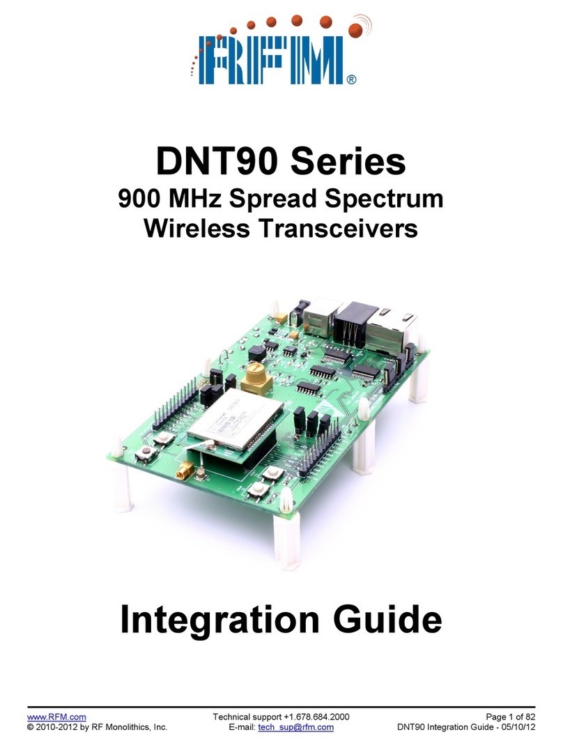
RFM DNT500 Series Quick setup guide

DNT500 Series
900 MHz Spread Spectrum Wireless
Industrial Transceivers
Integration Guide
3079 Premiere Pkwy Ste 140
Norcross, Georgia 30097
www.rfm.com
+1 (678) 684-2000

Important Regulatory Information
RFM Product FCC ID: HSW-DNT500P
IC 4492A-DNT500P
The DNT500 has been designed to operate with the RWA092R 2 dBi reverse-pin (polarity) SMA sleeved
dipole antenna (U.FL female to reverse-pin SMA female adaptor or equivalent required).
See section 3.10 of this manual for regulatory notices and labeling requirements. Changes or modifica-
tions not expressly approved by RFM may void the user’s authority to operate the module.
Note: This unit has been tested and found to comply with the limits for a Class B digital device,
pursuant to part 15 of the FCC Rules. These limits are designed to provide reasonable protection
against harmful interference when the equipment is operated in a commercial environment. This
equipment generates, uses, and can radiate radio frequency energy and, if not installed and used
in accordance with the instruction manual, may cause harmful interference to radio communica-
tions. Operation of this equipment in a residential area is likely to cause harmful interference in
which case the user will be required to correct the interference at their expense.

TABLE OF CONTENTS
1. INTRODUCTION................................................................................................................1
1.1 Why Spread Spectrum?...................................................................................................1
1.2 Frequency Hopping versus Direct Sequence ..................................................................2
2. DNT500 RADIO OPERATION ..........................................................................................4
2.1 Network Synchronization and Registration ....................................................................4
2.2 Transparent and Protocol Serial Port Modes................................................................... 4
2.3 RF Data Communications...............................................................................................5
2.4 RF Transmission Error Control.......................................................................................5
2.5 Network Configurations.................................................................................................. 6
2.5.1 Point-to-Point Network Operation..........................................................................6
2.5.2 Point-to-Multipoint Network Operation..................................................................7
2.6 Full-Duplex Serial Data Communications...................................................................... 7
2.7 Channel Access............................................................................................................... 7
2.7.1 CSMA Modes..........................................................................................................8
2.7.2 TDMA Modes .........................................................................................................9
2.7.3 Network Configuration Planning..........................................................................10
2.7.4 Serial Port Operation.............................................................................................12
2.7.5 Sleep Mode............................................................................................................13
3. DNT500 HARDWARE......................................................................................................14
3.1 Specifications................................................................................................................15
3.2 Module Interface ........................................................................................................... 16
3.3 Input Voltages...............................................................................................................17
3.4 ESD and Transient Protection.......................................................................................17
3.5 Interfacing to 5 V Logic Systems.................................................................................. 18
3.6 Power-On Reset Requirements .....................................................................................18
3.7 Analog RSSI Output...................................................................................................... 18
3.8 Mounting and Enclosures..............................................................................................18
3.9 Connecting Antennas .................................................................................................... 19
3.10 Labeling and Notices.....................................................................................................19
4. PROTOCOL MESSAGES.................................................................................................20
4.1 Protocol Message Formats............................................................................................20
4.1.1 Serial message types..............................................................................................20
4.1.2 Escape sequence....................................................................................................22
4.1.3 CFG select pin.......................................................................................................23
4.1.4 Flow control ..........................................................................................................23
4.1.5 Protocol mode data message example...................................................................23
4.2 Configuration Registers................................................................................................. 23
4.2.1 Bank 0 - Transceiver Setup...................................................................................24
4.2.2 Bank 1 - System Settings ......................................................................................26
4.2.3 Bank 2 - Status Registers (read only)...................................................................28
4.2.4 Bank 3 - Serial......................................................................................................30

4.2.5 Bank 4 - Host Protocol Settings...........................................................................31
4.2.6 Bank 5 - I/O Peripheral Registers ........................................................................33
4.2.7 Bank 6 - I/O setup ................................................................................................33
4.2.8 Bank FF - Special function...................................................................................36
4.2.9 Protocol Mode Configuration/Sensor Message Examples....................................36
4.2.10 Protocol Mode Event Message Examples.............................................................37
5. DNT500 DEVELOPER’S KIT ..........................................................................................38
5.1 DNT500DK Kit Contents..............................................................................................38
5.2 Additional Items Needed...............................................................................................38
5.3 Developer’s Kit Default Operating Configuration........................................................39
5.4 Development Kit Hardware Assembly .........................................................................39
5.5 DNT500 Wizard Utility Program.................................................................................. 41
5.6 DNT500 Interface Board Features................................................................................ 47
6. Demonstration Procedure...................................................................................................50
7. Troubleshooting..................................................................................................................51
8. APPENDICES....................................................................................................................52
8.1 Ordering Information ....................................................................................................52
8.2 Technical Support ......................................................................................................... 52
8.3 DNT500 Mechanical Specifications ............................................................................. 53
9. Warranty.............................................................................................................................55

DNT500
2008 by RF Monolithics, Inc. 1 M-0500-0000 Rev D
1. INTRODUCTION
The DNT500 series transceivers provide highly reliable wireless connectivity for either
point-to-point or point-to-multipoint applications. Frequency hopping spread spectrum
(FHSS) technology ensures maximum resistance to multipath fading and robustness in
the presence of interfering signals, while operation in the 900 MHz ISM band allows
license-free use in the US, Canada, Australia and New Zealand. The DNT500 supports
all standard serial data rates for host communications from 1.2 to 460.8 kb/s. On-board
data buffering and an error-correcting air protocol provide smooth data flow and sim-
plify the task of integration with existing applications. Key DNT500 features include:
-Multipath fading impervious fre-
quency hopping technology with
up to 50 frequency channels
(902 to 928 MHz).
- Supports point-to-point or multi-
point applications.
- Meets FCC rules 15.247 for li-
cense-free operation.
- 20 mile plus range with omni-
directional antennas.
- Transparent ARQ protocol with
buffering ensures data integrity.
- Selectable 0, 10, 19, 24, 27 or
28 dBm transmit power with a
firmware interlock of 19 dBm maxi-
mum for 500 kb/s operation.
- Built-in data scrambling reduces
possibility of eavesdropping.
- Nonvolatile memory stores configu-
ration when powered off.
- Dynamic TDMA slot assignment
that maximizes throughput.
- Simple serial interface handles both
data and control at up to 460.8 kb/s.
1.1 Why Spread Spectrum?
A radio transmission channel can be very hostile, corrupted by noise, path loss and
interfering transmissions from other radios. Even in an interference-free environment,
radio performance faces serious degradation through a phenomenon known as multi-
path fading. Multipath fading results when two or more reflected rays of the transmit-
ted signal arrive at the receiving antenna with opposing phases, thereby partially or
completely canceling the signal. This is a problem particularly prevalent in indoor in-
stallations. In the frequency domain, a multipath fade can be described as a fre-
quency-selective notch that shifts in location and intensity over time as reflections
change due to motion of the radio or objects within its range. At any given time, mul-
tipath fades will typically occupy 1% - 2% of the band. This means that from a prob-
abilistic viewpoint, a conventional radio system faces a 1% - 2% chance of signal im-
pairment at any given time due to multipath.
Spread spectrum reduces the vulnerability of a radio system to interference from both
jammers and multipath fading by distributing the transmitted signal over a larger re-
gion of the frequency band than would otherwise be necessary to send the informa-
tion. This allows the signal to be reconstructed even though part of it may be lost or
corrupted in transit.

DNT500
2008 by RF Monolithics, Inc. 2 M-0500-0000 Rev D
Figure1
Narrowband vs. spread spectrum in the presence of interference
1.2 Frequency Hopping versus Direct Sequence
The two primary approaches to spread spectrum are direct sequence spread spectrum
(DSSS) and frequency hopping spread spectrum (FHSS), either of which can gener-
ally be adapted to a given application. Direct sequence spread spectrum is produced
by multiplying the transmitted data stream by a much faster, noise-like repeating pat-
tern. The ratio by which this modulating pattern exceeds the bit rate of the base-band
data is called the processing gain, and is equal to the amount of rejection the system
affords against narrowband interference from multipath and jammers. Transmitting
the data signal as usual, but varying the carrier frequency rapidly according to a
pseudo-random pattern over a broad range of channels produces a frequency hopping
spectrum system.
Figure 2
Forms of spread spectrum

DNT500
2008 by RF Monolithics, Inc. 3 M-0500-0000 Rev D
One disadvantage of direct sequence systems is that due to spectrum constraints and
the design difficulties of broadband receivers, they generally employ only a minimal
amount of spreading (typically no more than the minimum required by the regulating
agencies). For this reason, the ability of DSSS systems to overcome fading and in-
band jammers is relatively weak. By contrast, FHSS systems are capable of probing
the entire band if necessary to find a channel free of interference. Essentially, this
means that a FHSS system will degrade gracefully as the channel gets noisier while a
DSSS system may exhibit uneven coverage or work well until a certain point and
then give out completely.
Because it offers greater immunity to interfering signals, FHSS is often the preferred
choice for co-located systems. Since direct sequence signals are very wide, they tend
to offer few non-overlapping channels, whereas multiple hoppers may interleave
with less interference. Frequency hopping does carry some disadvantage in that as
the transmitter cycles through the hopping pattern it is nearly certain to visit a few
blocked channels where no data can be sent. If these channels are the same from trip
to trip, they can be memorized and avoided. Unfortunately, this is generally not the
case, as it may take several seconds to completely cover the hop sequence during
which time the multipath delay profile may have changed substantially. To ensure
seamless operation throughout these outages, a hopping radio must be capable of
buffering its data until a clear channel can be found. A second consideration of fre-
quency hopping systems is that they require an initial acquisition period during
which the receiver must lock on to the moving carrier of the transmitter before any
data can be sent, which typically takes several seconds. In summary, frequency hop-
ping systems generally feature greater coverage and channel utilization than compa-
rable direct sequence systems. Of course, other implementation factors such as size,
cost, power consumption and ease of implementation must also be considered before
a final radio design choice can be made.
DNT500 series modules achieve regulatory certification under FHSS rules at air data
rates of 38.4, 115.2 and 200 kb/s. At 500 kb/s, the DNT500 series modules achieve
regulatory certification under “digital modulation” or DTS rules. At 500 kb/s
DNT500 series modules still employ frequency hopping to mitigate the effects of in-
terference and multipath fading, but hop on fewer, more widely spaced frequencies
than at lower data rates.

DNT500
2008 by RF Monolithics, Inc. 4 M-0500-0000 Rev D
2. DNT500 RADIO OPERATION
2.1 Network Synchronization and Registration
As discussed above, frequency hopping radios such as the DNT500 periodically change
the frequency at which they transmit. In order for the other radios in the network to re-
ceive the transmission, they must be listening to the frequency over which the current
transmission is being sent. To do this, all the radios in the network must be synchronized
and must be set to the same hopping pattern.
In point-to-point or point-to-multipoint networks, one radio module is designated as the
base station. All other radios are designated remotes. One of the responsibilities of the
base station is to transmit a synchronization signal to the remotes to allow them to syn-
chronize with the base station. Since the remotes know the hopping pattern, once they are
synchronized with the base station, they know which frequency to hop to and when.
Every time the base station hops to a different frequency, it immediately transmits a syn-
chronizing signal.
When a remote is powered on, it rapidly scans the frequency band for the synchronizing
signal. Since the base station is transmitting up to 50 frequencies and the remote is scan-
ning up to 50 frequencies, it can take several seconds for a remote to synchronize with
the base station.
Once a remote has synchronized with the base station, it will request registration informa-
tion to allow it to join the network. Registration can be handled automatically by the base
station, or it can be controlled by allowing the base station host application to authenti-
cate the remote for registration. When a remote is registered, it receives several network
parameters from the base station, including HopDuration, Nwk_ID, FrequencyBand and
Nwk_Key (see Section 5.2 for parameter details). Note that if a registration parameter is
changed at the base station, it will update the parameter in the remotes over the air.
Among other things, registration allows the tracking of remotes entering and leaving a
network, up to a limit of 255 remotes. The base station builds a table of serial numbers of
registered remotes using their three-byte serial numbers (MAC addresses). To detect if a
remote has gone offline or out of range, the registration is “leased” must be “renewed”
once every 250 hops. Any transmission from a remote running on a leased registration
will renew its lease with the base station.
2.2 Transparent and Protocol Serial Port Modes
DNT500 radios can work in two serial port data modes: transparent and packet protocol.
Transparent formatting is simply the raw user data. Packet protocol formatting uses a
framing character, length byte, addressing, command bytes, etc. Transparent mode opera-
tion is especially useful in point-to-point systems that act as simple cable replacements.
In point-to-multipoint systems where the base station needs to send data specifically to
each remote, protocol formatting must be used. Protocol formatting is also required for
configuration commands and responses, and sensor I/O commands and responses. Proto-
col formatting details are covered in Section 5.

DNT500
2008 by RF Monolithics, Inc. 5 M-0500-0000 Rev D
The DNT500 provides two ways to switch between transparent and protocol modes. If
CFG input Pin 18 on the DNT500 is switched from logic high to low, protocol mode is
invoked. Or if the ASCII escape sequence “DNT500” is sent (without quotation marks) to
the primary serial input following at least a 20 ms pause in data flow, the DNT500 will
switch to the protocol mode. When input Pin 18 is switched from logic low to high, or an
ExitProtocolMode command is sent to the primary serial input, the DNT500 will switch
to transparent operation. Note that if the escape sequence is used to switch to protocol
mode, the sequence will be transmitted before protocol mode is invoked.
When operating in transparent mode, two configuration parameters control when a
DNT500 radio will send the data in its transmit buffer. The MinPacketLength parameter
sets the minimum number of bytes that must be present in the transmit buffer to trigger a
transmission. The TxTimeout parameter sets the maximum time data in the transmit
buffer will be held before transmitting it, even if the number of data bytes is less than
MinPacketLength. The default value for both the MinPacketLength and the TxTimeout
parameters is zero, so that any bytes that arrive in the DNT500 transmit buffer will be
sent on the next hop. As discussed in Section 2.7.3, it is useful to set these parameters to
non-zero values in point-to-multipoint systems where some or all the remotes are in
transparent mode.
2.3 RF Data Communications
At the beginning of each hop, the base station transmits a synchronizing signal. After the
synchronizing signal has been sent, the base will transmit any user data in its transmit
buffer, unless in transparent mode the MinPacketLength and/or TxTimeout parameters
have been set to non-zero. The maximum amount of user data that the base station can
transmit per hop is limited by the BaseSlotSize parameter, which has a maximum value of
232 bytes. If there is no user data or reception acknowledgements (ACKs) to be sent on a
hop, the base station will only transmit the synchronization signal.
The operation for remotes is similar to the base station, but without the synchronizing
signal. The RemoteSlotSize parameter sets the maximum number of user bytes a remote
can transmit on one hop, up to a limit of 243 bytes per hop. The RemoteSlotSize must be
coordinated with the HopDuration and BaseSlotSize parameters and the number of regis-
tered remotes, as discussed in Section 2.5.3. The MinPacketLength and TxTimeout pa-
rameters operate in a remote in the same manner as in the base station.
2.4 RF Transmission Error Control
The DNT500 supports two error control modes: redundant transmissions and automatic
transmission repeats (ARQ). In both modes, the radio will detect and discard any dupli-
cates of messages it receives so that the host application will only receive one copy of a
given packet. Packet IDs are included in each transmission to allow recipients to identify
if the packet is new or has been received before.
In the redundant transmission mode, packets are repeated a fixed number of times with-
out any acknowledgement (ACK) from the recipient. This error control method is useful
in latency-critical applications such as voice, video and real-time telemetry, where only a

DNT500
2008 by RF Monolithics, Inc. 6 M-0500-0000 Rev D
few transmission repeats can be made before the current data is replaced with new data. It
is wasteful of bandwidth to send ACKs in these types of applications. Redundant trans-
missions are also used where messages are broadcast to multiple recipients and it is not
practical to receive ACKs from each one.
In ARQ mode, a packet is sent and an acknowledgement is expected on the next hop. If
an acknowledgement is not received, the packet is transmitted again on the next available
hop until either an ACK is received or the maximum number of attempts is exhausted. If
the AttemptLimit parameter is set to its maximum value, a packet transmission will be re-
tried without limit until the packet is acknowledged. This is useful in some point-to-point
cable replacement applications where it is important that data truly be 100% error-free,
even if the destination remote goes out of range temporarily.
2.5 Network Configurations
The DNT500 supports two network configurations: point-to-point and point-to-
multipoint. In a point-to-point network, one radio is set up as the base station and the
other radio is set up as a remote. In a point-to-multipoint network, a star topology is used
with the radio set up as a base station acting as the central communications point and all
other radios in the network set up as remotes. In this configuration, all communications
take place between the base station and any one of the remotes. Remotes cannot commu-
nicate directly with each other. It should be noted that point-to-point operation is a subset
of the point-to-multipoint operation, so there is no need to specify one or the other.
2.5.1 Point-to-Point Network Operation
Most point-to-point networks act as serial cable replacements and both the base station
and the remote use transparent mode. Unless the MinPacketLength and TxTimeout pa-
rameters have been set to non-zero, the base station will send the data in its transmit
buffer on each hop, up to the limit set by the BaseSlotSize parameter, less ACK bytes. If
the base station is buffering more data than can be sent on one hop, the remaining data
will be sent on subsequent hops. The base station adds the address of the remote, a packet
sequence number and error checking bytes to the data when it is transmitted. These addi-
tional bytes are not output at the remote in transparent mode. The sequence number is
used in acknowledging successful transmissions and in retransmitting corrupted transmis-
sions. A two-byte CRC and a one-byte checksum allows a received transmission to be
checked for errors. When a transmission is received by the remote, it will be acknowl-
edged if it checks error free. If no acknowledgment is received, the base station will re-
transmit the same data on the next hop.
In point-to-point operation, by default the remote will send the data in its transmit buffer
on each hop, up to the limit set by its RemoteSlotSize parameter. If desired, the MinPack-
etLength and TxTimeout parameters can be set to non-zero values, which configures the
remote to wait until the specified amount of data is available or the specified delay had
expired before transmitting. If the remote is buffering more data than can be sent on one
hop, it will send the remaining data in subsequent hops. The remote adds its own address,
a packet sequence number and error checking bytes to the data when it is transmitted.
These additional bytes are not output at the base station if the base station is in transpar-
ent mode. When a transmission is received by the base station, it will be acknowledged if

DNT500
2008 by RF Monolithics, Inc. 7 M-0500-0000 Rev D
it checks error free. If no acknowledgment is received, the remote will retransmit the
same data on the next hop.
2.5.2 Point-to-Multipoint Network Operation
In a point-to-multipoint network, the base station is usually configured for protocol for-
matting, unless the applications running on each remote can determine the data’s destina-
tion from the data itself. Protocol formatting adds the address of the destination (remote)
and other overhead bytes to the user data. If the addressed remote is using transparent for-
matting, the destination address and the other overhead bytes are removed. If the remote
is using protocol formatting, the destination address and the other overhead bytes are out-
put with the user data.
A remote can operate in a point-to-multipoint network using either transparent or proto-
col formatting, as the base station is always the destination. In transparent operation, a
remote will add addressing, a packet sequence number and error checking bytes as in a
point-to-point network. When the base station receives the transmission, it will format the
data to its host according to its formatting configuration. A remote running in transparent
mode in a point-to-multipoint network will often have the MinPacketLength and TxTime-
out parameters set to non-zero values to reduce the chance of transmission collisions.
This is covered in more detail in section 2.6.3.
2.6 Full-Duplex Serial Data Communications
From an host application’s perspective, DNT500 serial communications appear full du-
plex. Both the base station host application and each remote host application can send
and receive serial data at the same time. At the radio level, the base station and remotes
do not actually transmit at the same time. If they did, the transmissions would collide. As
discussed earlier, the base station transmits a synchronization signal at the beginning of
each hop followed by its user data. After the base station transmission, the remotes can
transmit. Each base station and remote transmission may contain all or part of a complete
message from its host application. From an application’s perspective, the radios are
communicating in full duplex since the base station can receive data from a remote before
it completes the transmission of a message to the remote and visa versa.
2.7 Channel Access
The DNT500 provides two methods of channel access: CSMA or TDMA. Each method
supports several options as shown in the table below. The channel access setting is dis-
tributed to all remotes in the base station status packet, so changing it at the base station
sets the entire network. Carrier Sense Multiple Access (CSMA) is very effective at han-
dling packets with varying amounts of data and/or packets sent at random times from a
large number of remotes. The DNT500 includes a CSMA polling mode for coordinated
remotes and a CSMA contention mode for uncoordinated and/or reporting remotes. Time
Division Multiple Access (TDMA) provides a scheduled time slot for each remote to
transmit on each hop. The default DNT500 access mode is CSMA polling.

DNT500
2008 by RF Monolithics, Inc. 8 M-0500-0000 Rev D
Access Mode Description Max # of Remotes Remote Slot Size
0 CSMA polling 1024 manual
1 CSMA contention 1024 manual
2 (default) TDMA dynamic slots up to 15 automatic
3 TDMA fixed slots up to 15 automatic
4 TDMA with PTT 1024 automatic
2.7.1 CSMA Modes
When using CSMA, each remote with data to send listens to see if the channel is clear
and then transmits. If the channel is not clear, a remote will wait a random period of time
and listen again. CSMA works best when a large or variable number of remotes transmit
infrequent bursts of data. There is no absolute to the number of remote radios that can be
supported in this mode. For a DNT500 network, a maximum of 255 remotes can be sup-
ported if base station join-leave tracking is required, or a maximum of 1024 remotes is
suggested if base station join-leave tracking is not required. The illustration below com-
pares TDMA to CSMA operation.
There are two important parameters related to CSMA operation. The CSMA_MaxBackoff
parameter defines the maximum time that a remote will wait after a collision before at-
tempting to send the packet again (back-off interval). The CSMA_Persistence parameter
sets the probability that a remote will transmit immediately rather than first waiting for a
pre-transmit delay interval. Persistence is a one-byte parameter with a range of 0x00 to
0xFF:
0xFF = 100% probability
0x00 = 0% probability
CSMA polling (Mode 0) is used for point-to-point systems and point-to-multipoint sys-
tems where only one remote at a time can receive data to transmit (ModBus, etc.). Since
only one remote will attempt to transmits at a time, the CSMA_Persistence parameter is
fixed at 0xFF for minimum latency. This mode provides maximum throughput since
there is no contention between remotes and the entire portion of the hop frame following
the base station transmission is available for a remote to transmit. The user can set

DNT500
2008 by RF Monolithics, Inc. 9 M-0500-0000 Rev D
CSMA_MaxBackoff, BaseSlotSize and RemoteSlotSize parameters when using this mode.
Note that a CSMA_Persistence parameter setting of 0xFF would lead to collisions if more
than one remote tried to transmit. Applications where more than one remote can receive
serial data to transmit at the same time, or where periodic reporting and/or event report-
ing are enabled should not use this mode.
CSMA Contention (Mode 1) provides classical CSMA channel access, and gives the user
control over both the CSMA_MaxBackoff and CSMA_Persistence parameters. This mode
is well-suited for large numbers of uncoordinated remotes, and/or where periodic/event
reporting is used. In addition to CSMA_MaxBackoff and CSMA_Persistence, the user can
set the BaseSlotSize and RemoteSlotSize parameters when using this mode. The following
guidelines are suggested for setting CSMA_Persistence:
•For lightly loaded CSMA contention networks, increase CSMA_Persistence to
0x80 or higher to reduce latency.
•For heavily loaded CSMA contention networks, reduce CSMA_Persistence to
0x20 or lower for better throughput.
CSMA modes can optionally track remotes entering and leaving the network for up to
255 remotes. The base station is operated in protocol mode and is configured to generate
a CONNECT message for its host when a remote registers, and a DISCONNECT mes-
sage when the remote’s registration lease expires.
The base station in a CSMA network can generate CONNECT messages for more than
255 remotes. This allows the host application to track remotes entering and leaving a
large CSMA network by creating a table of MAC addresses and periodically sending a
ping to each remote in the table. Failure to answer the ping indicates the remote is no
longer active in the network.
The CSMA modes work well in many applications, but CSMA does have some limita-
tions, as summarized below:
•Bandwidth is not guaranteed to any remote.
•Marginal RF links to some remotes can create a relatively high chance of
collisions in heavily loaded networks.
2.7.2 TDMA Modes
The TDMA modes provide guaranteed bandwidth to some or all of the remotes in the
network. Remotes that register with the base station receive several special parameters,
including ranging information and a specific channel access slot assignment. TDMA reg-
istrations are always leased and must be renewed every 250 hops. The DNT500 provides
three different modes of TDMA access, as discussed below.
TDMA Dynamic Slots (Mode 2) is used for general-purpose TDMA applications where
scaling the capacity per slot to the number of active remotes is automatic. Each remote
that registers with the base receives an equal time slice. As new remotes join, the size of
the TDMA slots shrink accordingly. The number of slots, individual slot start times, and

DNT500
2008 by RF Monolithics, Inc. 10 M-0500-0000 Rev D
the RemoteSlotSize are computed automatically by the DNT500 network in this mode.
The user should note that the bandwidth to each remote will change immediately as re-
motes join and leave the network.
TDMA Fixed Slots (Mode 3) is used for applications that have fixed data throughput re-
quirements, such as isochronous voice or streaming telemetry. The slot start time and the
RemoteSlotSize are computed automatically by the DNT500 network in this mode. The
user must set the number of slots.
TDMA with PTT (Mode 4) supports remotes with a "push-to-talk" feature, also referred
to as "listen-mostly" remotes. This mode uses fixed slot allocations. Remotes can be reg-
istered for all but the last slot. The last slot reserved for the group of remotes that are usu-
ally listening, but occasionally need to transmit. In essence, the last slot is a shared chan-
nel for this group of remotes. When one of them has data to send it keys its transmitter
much like a walkie-talkie, hence the name push-to-talk (PTT).
The slot start time and the RemoteSlotSize are computed automatically by the DNT500
network in this mode. The user must specify the number of slots. The last slot is reserved
for the PTT remotes. The user must configure PTT remotes individually to select Mode 4
operation. The network makes no guarantee that PTT remote transmissions will not col-
lide in the shared slot. The user's application must ensure that no more than one PTT re-
mote is using the slot at a time.
2.7.3 Network Configuration Planning
Some planning is necessary for a DNT500 network to coordinate the RF_DataRate,
HopDuration, BaseSlotSize, RemoteSlotSize, MinPacketLength, TxTimeout and
TDMA_MaxNumSlots parameters to achieve a practical configuration. This is true even
for modes that automatically compute some of these parameters. Each parameter has a
limited range of usable values, as shown in the table below:
Parameter Useable Range Value
RF_DataRate 0..3 500, 200, 115.2 and 38.4 kb/s
HopDuration 40..4095 2..204.75 ms (0.05 ms/count)
TDMA_MaxNumSlots 1..15 max number of TDMA slots (MNS) for remotes
BaseSlotSize 6..232 max number of user data bytes transmitted per hop
RemoteSlotSize 3..243 max number of user data bytes transmitted per hop
MinPacketLength 0..255 0..255 bytes
TxTimeOut 0..255 0..255 ms (1 ms/count)
The highest RF data rate, 500 kb/s, provides the highest throughput and the most flexibil-
ity with respect to the other parameters. The maximum RF power that can be used at
500 kb/s is 19 dBm. The three lower data rates can run up to 28 dBm of RF power, and
the receiver becomes progressively more sensitive as the data rate is lowered. So for
greatest operating range, one of the three lower RF data rates should be used.
The maximum DNT500 HopDuration setting is about 200 ms regardless of the RF data
rate chosen. For a given data rate, FHSS operation tends to become more robust as hop
duration is reduced. However, running with a shorter hop duration may require setting the

DNT500
2008 by RF Monolithics, Inc. 11 M-0500-0000 Rev D
BaseSlotSize and RemoteSlotSize parameters well below their maximum values at the
lower RF data rates. The equation below calculates the minimum hop duration needed at
a given RF data rate for a specific number of remote slots and BaseSlotSize and Re-
moteSlotSize parameter settings. Support for optimizing a DNT500 configuration for a
specific application is also available from RFM’s Technical Support Group. See Section
10.3. for technical support contact information.
The minimum required hop duration for a DNT500 configuration is:
THD = TBRO + NRS*TRO + TRFB*(BBSS + NRS*BRSS)
Where:
T
HD is the minimum required hop duration in milliseconds
T
BRO is the base and registration request overhead time for each hop (RF data rate dependent)
N
RS is the number of remote slots
T
RO is the remote overhead time for each hop (RF data rate dependent)
T
RFB is the transmission time for one user byte (RF data rate dependent)
B
BSS is the BaseSlotSize parameter in bytes
B
RSS is the RemoteSlotSize parameter in bytes
The constants in the equation for each RF data rate are given in the following table:
RF Data Rate
kb/s TBRO
ms TRO
ms TRFB
ms
38.40 11.620 4.817 0.2080
115.2 4.953 2.039 0.0694
200 3.540 1.450 0.0400
500 2.388 0.970 0.0160
For Example 1, consider a point-to-point CSMA Mode 0 system operating at 38.4 kb/s
with the BaseSlotSize parameter set to 133 bytes and the RemoteSlotSize parameter set to
128 bytes. The minimum hop duration needed to support one-hop transmissions of full
slot size messages in both directions for this configuration is:
= 11.620 + 1*4.817 + 0.2080*(133 + 1*128)
= 16.437 + 0.2080*261
= 70.725 ms
The closest programmable hop duration is 70.750 ms.
It should be noted that the base station operating system will commandeer 5 bytes from
the BaseSlotSize allocation in Mode 0 and up to 13 bytes in Mode 1 to send reception ac-
knowledgements (ACKs) back to the remotes. The BaseSlotSize should be sized accord-
ingly. In the above example, the BaseSlotSize parameter is set five bytes larger than the
RemoteSlotSize parameter to accommodate the ACK bytes.
When running a point-to-multipoint network with uncoordinated remotes using CSMA
Mode 1, it is useful to set NRS to a value of 3 or higher in the equation. Although CSMA

DNT500
2008 by RF Monolithics, Inc. 12 M-0500-0000 Rev D
does not create reserved time slots for remotes, extending the hop duration this way al-
lows several uncoordinated transmissions of user data and/or periodic/event reports to ar-
rive in the same slot with a relatively few collisions.
The performance of a CSMA Mode 1 system can often be helped by setting the Min-
PacketLength and TxTimeout parameters on any remotes running transparent mode to
non-zero values, especially if host messages only contain a few bytes each and transmis-
sion latency is not critical. For starting point values, set the MinPacketLength equal to the
RemoteSlotSize and TxTimeout to at least three times the hop duration. This will help
avoid excessive transmission collisions due to having many packets transmitted, each car-
rying only a small amount of user data on top of the relatively large packet overhead
structure.
For Example 2, consider a TDMA Mode 2 or 3 system operating at 500 kb/s. Up to 10
registered remotes need to be accommodated. A BaseSlotSize of 138 bytes is needed, and
each remote needs enough slot time to support a RemoteSlotSize of 64 bytes. The mini-
mum hop duration needed to support this configuration is:
= 2.388 + 10*0.970 + 0.0160*(138 + 10*64)
= 12.088 + 0.0160*778
= 24.536 ms
The closest programmable hop duration is 24.550 ms.
In all TDMA modes, the base station operating system will commandeer one byte from
the BaseSlotSize allocation for each registered remote to send ACKs to the remotes. The
BaseSlotSize and MinPacketLength should be sized accordingly.
2.7.4 Serial Port Operation
DNT500 networks are often used for wireless communication of serial data. The
DNT500 supports serial baud rates from 1.2 to 460.8 kb/s. Listed in the table below are
the supported data rates and their related byte data rates and byte transmission times for
an 8N1 serial port configuration:
Baud Rate
kb/s Byte Data Rate
kB/s Byte Transmission Time
ms
1.2 0.12 8.3333
2.4 0.24 4.1667
4.8 0.48 2.0833
9.6 0.96 1.0417
19.2 1.92 0.5208
38.4 3.84 0.2604
115.2 11.52 0.0868
230.4 23.04 0.0434
460.8 46.08 0.0217
To support continuous full-duplex serial port data flow, an RF data rate much higher than
the serial port baud rate is required for FHSS. Radios transmissions are half duplex, and

DNT500
2008 by RF Monolithics, Inc. 13 M-0500-0000 Rev D
there are overheads related to hopping frequencies, assembling packets from the serial
port data stream, transmitting them, sending ACK’s to confirm error-free reception, and
occasional transmission retries when errors occur.
For Example 3, consider a CSMA Mode 0 transparent data system operating at 500 kb/s
with the BaseSlotSize parameter set to 133 bytes (128 bytes net after the five byte alloca-
tion for sending ACKs) and the RemoteSlotSize parameters set to 128 bytes. The mini-
mum hop duration needed to efficiently support this configuration is:
= 2.388 + 1*0.970 + 0.0160*(133 +1*128)
= 3.358 + 0.0160*261
= 7.534 ms
Setting the hop duration to 7.55 ms, the average full-duplex serial port byte rate that can
be supported under error free conditions is:
128 Bytes /7.55 ms = 16.942 kB/s, or 169.42 kb/s for 8N1
Continuous full-duplex serial port data streams at a baud rate of 115.2 k/bs can be sup-
ported by this configuration, provided only occasional RF transmission errors occur. Plan
on an average serial port data flow of 75% of the calculated error-free capacity for gen-
eral-purpose applications, and 50% of the calculated error-free capacity for RF challeng-
ing applications such as vehicle telemetry and heavy industrial process environments.
Most applications do not require continuous serial port data flow. The DNT500 transmit
and receive buffers hold at least 1024 bytes and will accept brief bursts of data at high
baud rates, provided the average serial port data flow such as shown in Example 3 is not
exceeded. It is strongly recommended that the DNT500 host use hardware flow control.
The host must send no more than 32 bytes additional bytes to the DNT500 when the
DNT500 de-asserts the hosts CTS line. In turn, the DNT500 will send no more than one
byte following the host de-asserting its RTS line. Three-wire serial port operation is al-
lowed by connecting the DNT500 CTS output to its RTS input. However, three-wire op-
eration should be limited to applications that send small bursts of data occasionally at an
average serial port data flow less than 50% of the calculated error-free capacity. Data loss
is possible under adverse RF channel conditions when using three-wire serial operation.
2.7.5 Sleep Mode
To save power in applications where a remote transmits infrequently, the DNT500 sup-
ports a Sleep Mode. Sleep Mode is entered by switching DTR Pin 11 on the DNT500
from logic low to high. While in Sleep Mode, the DNT500 consumes less than 0.5 mA.
This mode allows a DNT500 to be powered off while its host device remains powered.
After leaving Sleep Mode (Pin 11 low to high), the radio must re-synchronize with the
base station and re-register.

DNT500
2008 by RF Monolithics, Inc. 14 M-0500-0000 Rev D
3. DNT500 HARDWARE
2 3 2 4 2 5 2 6 2 7 2 82 22 1 2 9 3 0 3 1
1 8
1 7
1 6
1 5
1 4
1 3
1 2
1 1
1 0
9
8
7
6
5
D N T 5 0 0 B l o c k D i a g r a m
3 2 3 3 3 4 3 6
M i c r o c o n t r o l l e r
4
3
2
1
R e g
F i l t e r
F i l t e r
V
P W M A
P W M B
G P I O 0
G P I O 1
G P I O 2
G P I O 3
G N D
4 2
R a d i o
L K
I N T
S n R F I O
G N D
U A R T 0 _ R X D
U A R T 0 _ T X D
/ R E S E T
S P I _ N S S
S P I _ M O S I
S P I _ M I S O
T / R
T / R
P W R
P R E
F i l t e r
3 5
4 1
4 3
1 9
2 0
3 7 3 8 3 9 4 0
S I
S O
P K T D E T
R e g
3 . 3 V
3 . 6 V
R S V D
R S V D
A D _ R E F
R S S I
D T R
A D X
A D Y
A D Z
E X _ S Y N
U A R T 1 _ R X D
U A R T 1 _ T X D
F G
U A R T 0 _ R T S
U A R T 0 _ T S
G P I O 4
G P I O 5
R S V D
A T
D D
R S V D
R S V D
R S V D
V M O D
S P I _ S L K
B O O T _ L O A D
The major components of the DNT500 include a 900 MHz FHSS transceiver and a 32-bit
microcontroller. The DNT500 operates in the frequency band of 902 to 928 MHz. There
are 32 selectable hopping patterns including patterns compatible the frequency alloca-
tions in the US, Canadian, Australian and New Zealand. The DNT500 has six selectable
RF output power levels: 0, 10, 19, 24, 27 and 28 dBm. Also, there are four selectable RF
transmission rates: 38.4, 115.2, 200 and 500 kb/s. The power level is firmware inter-
locked to a maximum of 19 dBm at 500 kb/s to assure regulatory compliance.
The DNT500 includes a low-noise preamplifier protected by two SAW filters, providing
an excellent blend of receiver sensitivity and out-of-band interference rejection.
The DNT500 provides a variety of hardware interfaces. There are two UART serial ports,
one for data and a second for diagnostics. The data port supports baud rates from 1.2 to
460.8 kb/s and the diagnostic port supports baud rates from 38.4 to 460.8 kb/s. Other
hardware interfaces include an SPI interface, three 10-bit ADC inputs, two 8-bit resolu-
tion PWM (DAC) outputs, and six general purpose digital I/O ports. Four of the digital
I/O ports support an optional interrupt-from-sleep mode when configured as inputs. A
3.6 Vdc signal can be switched on the RF output port for diversity antenna control. The
radio is available in two mounting configurations. The DNT500 is designed for solder re-
flow mounting. The DNT500P is designed for plug-in connector mounting.

DNT500
2008 by RF Monolithics, Inc. 15 M-0500-0000 Rev D
3.1 Specifications
The DNT500 specifications are listed in the table below:
Characteristic Sym
Notes
Minimum Typical Maximum Units
Operating Frequency Range 902.75 927.25 MHz
FCC 15.247 FHSS 1 38.4, 115.2 and 200 kb/s, up to 28 dBm
FCC 15.247 Digital Modulation (DSS) 1 500 kb/s, up to 19 dBm
Number of Hopping Patterns 32
Hop Dwell Time 5 200 ms
Number of RF Channels 50
RF Data Transmission Rates 1 38.4, 115.2, 200 and 500 kb/s
Receiver Sensitivity
10-5 BER @ 38.4 kb/s -108 dBm
10-5 BER @ 500 kb/s -94 dBm
Transmitter RF Output Power Levels 1 0, 10, 19, 24, 27, 28 dBm
Optimum Antenna Impedance 50 Ω
RF Connection U.FL Connector or PCB Pad
Network Topologies Point-to-Point, Point-to-Multipoint, Mesh
Access Schemes TDMA and CSMA
Number of Network Nodes
TDMA 15
CSMA 1024
ADC Input Range 0 3.3 V
ADC Input Resolution 10 bits
Signal Source Impedance for ADC Reading 10 KΩ
PWM (DAC) Output Range 0 3.3 V
PWM (DAC) Output Resolution 8 bits
Primary Serial Port Baud Rates 1.2, 2.4, 4.8, 9.6, 19.2, 38.4, 115.2, 230.4, 460.8 kb/s
Diagnostic Serial Port Baud Rates 38.4, 115.2, 230.4, 460.8 kb/s
Digital I/O:
Logic Low Input Level -0.5 0.8 V
Logic High Input Level 2 3.3 V
Logic Input Internal Pull-up Resistor 50 200 KΩ
Logic Input Internal Pull-down Resistor 50 180 KΩ
Power Supply Voltage Range VCC +3.3 +5.5 Vdc
Power Supply Voltage Ripple 10 mVP-P
Receive Mode Current 50 mA
Transmit Mode Current 900 mA
DTR High Sleep Current 0.5 mA
Operating Temperature Range -40 85 oC
Operating Relative Humidity Range 10 90 %
1. RF output power is interlocked in firmware to a maximum of 19 dBm at the 500 kb/s RF data rate to assure compliance
with regulatory requirements.

DNT500
2008 by RF Monolithics, Inc. 16 M-0500-0000 Rev D
3.2 Module Interface
Electrical connections to the DNT500 are made through the I/O pads and through the I/O
pins on the DNT500P. The hardware I/O functions are detailed in the table below:
Pad Name Description
1 RSVD Reserved pad. Leave unconnected.
2 RSVD Reserved pad. Leave unconnected.
3 ADC_REF ADC supply and external full scale reference voltage input. Voltage range is 2.4 to 3.3 Vdc.
Connect pad 34 to this input to reference the ADC full scale reading to the module’s 3.3 V
regulated supply.
4 RSSI Analog voltage proportional to received signal strength, range 0 to 3.3 V.
5 GPIO0 Configurable digital I/O port 0. When configured as an input, an internal pull-up resistor can be
selected and interrupt from sleep can be invoked. When configured as an output, the power-on
state is also configurable.
6 GPIO1 Configurable digital I/O port 1. Same configuration options as GPIO0.
7 GPIO2 Configurable digital I/O port 2. Same configuration options as GPIO0.
8 GPIO3 Configurable digital I/O port 3. Same configuration options as GPIO0.
9 PWM0 Pulse-width modulated output 0 with internal low-pass filter. Provides an 8-bit DAC resolution.
10 PWM1 Pulse-width modulated output 1 with internal low-pass filter. Provides an 8-bit DAC resolution.
11 SLEEP Default functionality is active high module sleep input. When switched low after sleep, the
module executes a power-on reset.
12 ADC0 10-bit ADC input 0. Full scale reading is referenced to the ADC_REF input.
13 ADC1 10-bit ADC input 1. Full scale reading is referenced to the ADC_REF input.
14 ADC2 10-bit ADC input 2. Full scale reading is referenced to the ADC_REF input.
15 EX_SYNC Optional rising-edge triggered input for synchronizing co-located base stations. See External-
SyncEn on Page 25 for additional details.
16 DIAG_TX Diagnostic output (for factory use).
17 DIAG_RX Diagnostic input (for factory use).
18 /CFG Protocol selection input. Leave unconnected when using software commands to select trans-
parent/protocol mode (default is transparent mode). Logic low selects protocol mode, logic high
selects transparent mode.
19 VCC Power supply input, +3.3 to +5.5 Vdc.
20 GND Power supply and signal ground. Connect to the host circuit board ground.
21 GND Power supply and signal ground. Connect to the host circuit board ground.
22 GPIO4 Configurable digital I/O port 4. When configured as an input, an internal pull-up resistor can be
selected. When configured as an output, the power-on state is configurable.
23 GPIO5 Configurable digital I/O port 5. Same configuration options as GPIO4.
24 RSVD Reserved pad. Leave unconnected.
25 ACT Data activity output, logic high when data is being transmitted or received.
26 /DCD Default functionality is data carrier detect output, which provides a logic low on a remote when
the module is locked to FHSS hopping pattern and logic low on a base station when at least
one remote is connected to it.
Table of contents
Other RFM Transceiver manuals