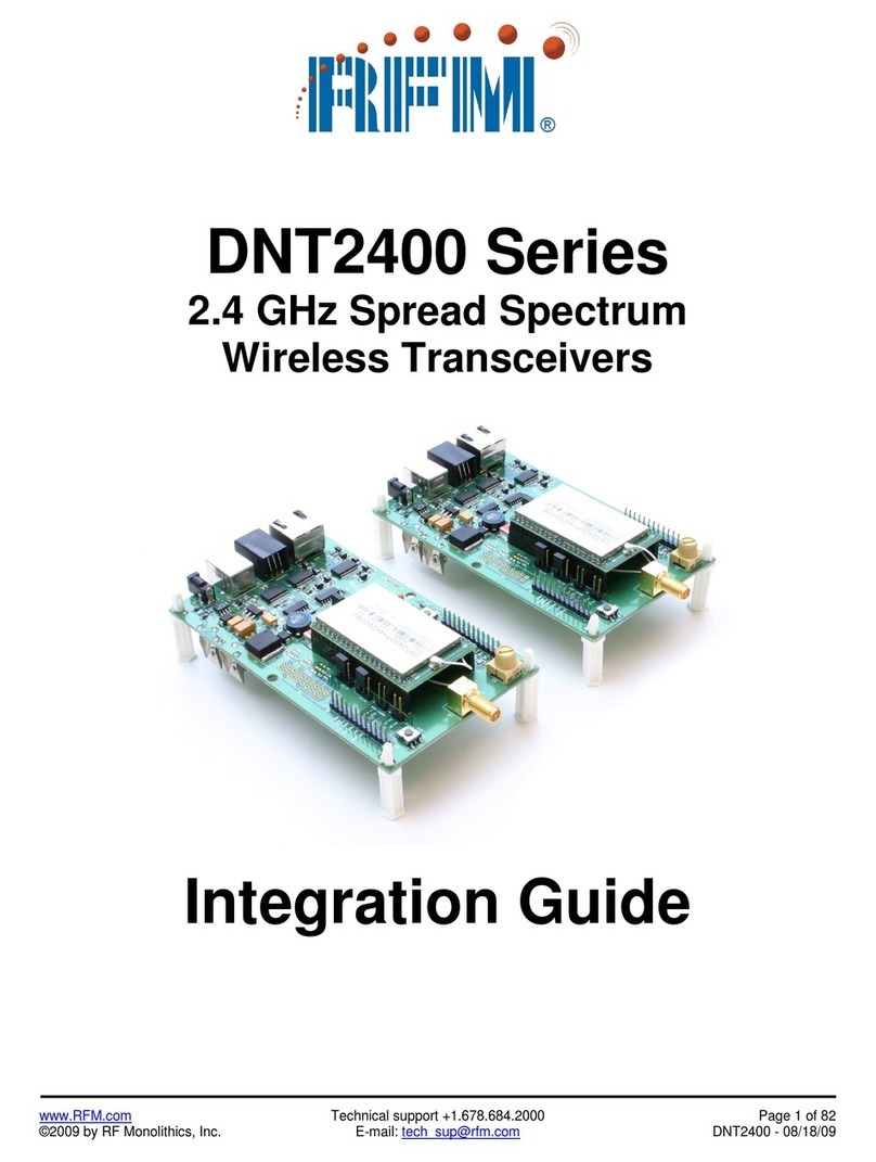
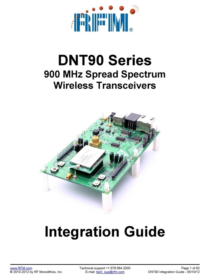
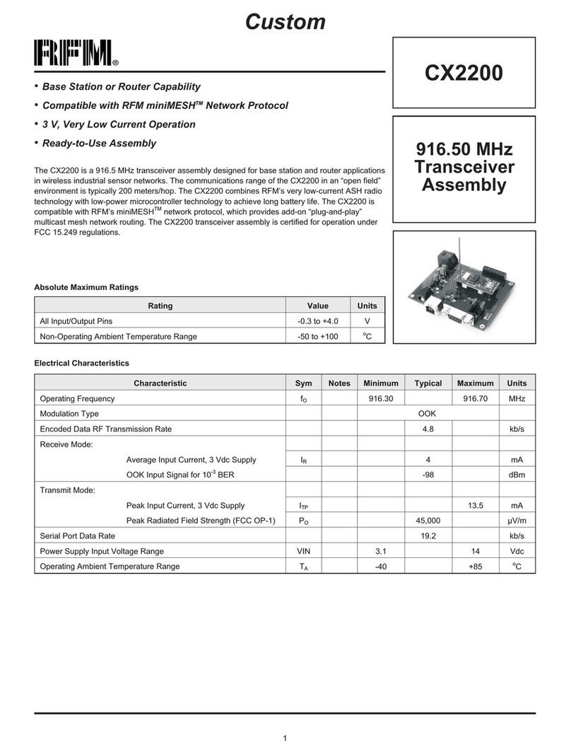
RFM DNT900 Series Quick setup guide

www.RFM.com Technical support +1.678.684.2000 Page 1 of 96
©2009-2010 by RF Monolithics, Inc. E-mail: tech_sup@rfm.com DNT900 - 08/16/10
DNT900 Series
900 MHz Spread Spectrum
Wireless Transceivers
Integration Guide

www.RFM.com Technical support +1.678.684.2000 Page 2 of 96
©2009-2010 by RF Monolithics, Inc. E-mail: tech_sup@rfm.com DNT900 - 08/16/10
Important Regulatory Information
RFM Product FCC ID: HSW-DNT900P
IC 4492A-DNT900P
Note: This unit has been tested and found to comply with the limits for a Class B digital device, pursuant
to Part 15 of the FCC Rules. These limits are designed to provide reasonable protection against harmful
interference when the equipment is operated in a commercial environment. This equipment generates,
uses, and can radiate radio frequency energy and, if not installed and used in accordance with the in-
struction manual, may cause harmful interference to radio communications. Operation of this equipment
in a residential area is likely to cause harmful interference in which case the user will be required to
correct the interference at their expense.
FCC Antenna Gain Restriction:
The DNT900 has been designed to operate with any dipole antenna of up to 5.1 dBi of gain, or any Yagi
of up to 6.1 dBi gain.
The antenna(s) used for this transmitter must be installed to provide a separation distance of at least
20 cm from all persons and must not be co-located or operating in conjunction with any other antenna or
transmitter.
IC RSS-210 Detachable Antenna Gain Restriction:
This device has been designed to operate with the antennas listed below, and having a maximum gain of
6.1 dB. Antennas not included in this list or having a gain greater than 6.1 dB are strictly prohibited for
use with this device. The required antenna impedance is 50 ohms:
RFM RWA092R Omnidirectional Dipole Antenna, 2 dBi
RFM OMNI095 Omnidirectional Dipole Antenna, 5 dBi
RFM YAGI099 Directional Antenna, 6.1 dBi
To reduce potential radio interference to other users, the antenna type and its gain should be so chosen
that the equivalent isotropically radiated power (e.i.r.p.) is not more than that permitted for successful
communication.
See Section 3.9 of this manual for regulatory notices and labeling requirements. Changes or modifica-
tions to a DNT900 not expressly approved by RFM may void the user’s authority to operate the module.

www.RFM.com Technical support +1.678.684.2000 Page 3 of 96
©2009-2010 by RF Monolithics, Inc. E-mail: tech_sup@rfm.com DNT900 - 08/16/10
Table of Contents
1.0 Introduction ...................................................................................................................................... 5
1.1 Why Spread Spectrum? ............................................................................................................... 5
1.2 Frequency Hopping versus Direct Sequence............................................................................... 6
2.0 DNT900 Radio Operation................................................................................................................ 7
2.1 Network Synchronization and Registration .................................................................................. 7
2.2 Authentication............................................................................................................................... 8
2.3 Serial Port Modes......................................................................................................................... 9
2.4 SPI Port Modes ............................................................................................................................ 9
2.5 RF Data Communications .......................................................................................................... 10
2.6 RF Transmission Error Control................................................................................................... 10
2.7 Transmitter Power Management................................................................................................ 10
2.8 Network Configurations.............................................................................................................. 11
2.8.1 Point-to-Point Network Operation ........................................................................................... 11
2.8.2 Point-to-Multipoint Network Operation.................................................................................... 11
2.8.3 Multipoint Peer-to-Peer Network Operation............................................................................ 12
2.8.4 Tree-Routing System Operation ............................................................................................. 12
2.9 Full-Duplex Serial Data Communications................................................................................... 12
2.10 Channel Access.......................................................................................................................... 12
2.10.1 Polling Mode ........................................................................................................................... 13
2.10.2 CSMA Mode............................................................................................................................ 14
2.10.3 TDMA Modes .......................................................................................................................... 15
2.11 Point-to-Point and Point-to-Multipoint Networks......................................................................... 15
2.11.1 TDMA Throughput................................................................................................................... 16
2.11.2 Polling Throughput.................................................................................................................. 16
2.11.3 CSMA Throughput................................................................................................................... 17
2.11.4 Latency.................................................................................................................................... 18
2.11.5 Configuration Validation.......................................................................................................... 18
2.12 Tree-Routing Systems................................................................................................................ 20
2.12.1 Example Tree-Routing System............................................................................................... 20
2.12.2 Tree-Routing System Networks.............................................................................................. 22
2.12.3 Tree-Routing System Addressing........................................................................................... 23
2.12.4 Tree-Routing System Implementation Options....................................................................... 24
2.13 Serial Port Operation.................................................................................................................. 25
2.14 SPI Port Operation ..................................................................................................................... 26
2.15 Sleep Modes............................................................................................................................... 29
2.16 Encryption................................................................................................................................... 31
2.17 Synchronizing Co-located Bases ............................................................................................... 31
3.0 DNT900 Hardware......................................................................................................................... 32
3.1 Specifications ............................................................................................................................. 33
3.2 Module Interface......................................................................................................................... 34
3.3 DNT900 Antenna Connector...................................................................................................... 35
3.4 Input Voltages............................................................................................................................. 36
3.5 ESD and Transient Protection.................................................................................................... 36
3.6 Interfacing to 5 V Logic Systems................................................................................................ 36
3.7 Power-On Reset Requirements ................................................................................................. 37
3.8 Mounting and Enclosures........................................................................................................... 37
3.9 Labeling and Notices.................................................................................................................. 37

www.RFM.com Technical support +1.678.684.2000 Page 4 of 96
©2009-2010 by RF Monolithics, Inc. E-mail: tech_sup@rfm.com DNT900 - 08/16/10
4.0 Protocol Messages ........................................................................................................................ 39
4.1 Protocol Message Formats......................................................................................................... 39
4.1.1 Message Types....................................................................................................................... 39
4.1.2 Message Format Details ......................................................................................................... 40
4.1.3 /CFG Select Pin....................................................................................................................... 42
4.1.4 Flow Control ............................................................................................................................ 42
4.1.5 Protocol Mode Data Message Example.................................................................................. 42
4.1.6 Protocol Mode Tree-Routing MAC Address Discovery Example............................................ 43
4.2 Configuration Registers.............................................................................................................. 43
4.2.1 Bank 0 - Transceiver Setup..................................................................................................... 43
4.2.2 Bank 1 - System Settings........................................................................................................ 47
4.2.3 Bank 2 - Status Registers ....................................................................................................... 49
4.2.4 Bank 3 - Serial and SPI Settings............................................................................................. 51
4.2.5 Bank 4 - Host Protocol Settings .............................................................................................. 54
4.2.6 Bank 5 - I/O Peripheral Registers ........................................................................................... 55
4.2.7 Bank 6 - I/O Setup................................................................................................................... 56
4.2.8 Bank 7 - Authentication List .................................................................................................... 58
4.2.9 Bank 8 - Tree-Routing Active Router ID Table ....................................................................... 58
4.2.10 Bank 9 - Registered MAC Addresses ..................................................................................... 58
4.2.11 Bank FF - Special Functions................................................................................................... 59
4.2.12 Protocol Mode Configuration Message Example.................................................................... 60
4.2.13 Protocol Mode Sensor Message Example.............................................................................. 60
4.2.14 Protocol Mode Event Message Example................................................................................ 61
5.0 DNT900DK Developer’s Kit........................................................................................................... 62
5.1 DNT900DK Kit Contents............................................................................................................. 62
5.2 Additional Items Needed ............................................................................................................ 62
5.3 Developer’s Kit Operational Notes ............................................................................................. 62
5.4 Developer’s Kit Default Operating Configuration ....................................................................... 63
5.5 Developer’s Kit Hardware Assembly.......................................................................................... 63
5.6 DNT900 Demo Utility Program................................................................................................... 65
5.6.1 Initial Kit Operation.................................................................................................................. 66
5.6.2 Serial Communication and Radio Configuration..................................................................... 69
5.7 DNT900 Wizard Utility Program ................................................................................................. 76
5.8 DNT900 Interface Board Features ............................................................................................. 84
6.0 Demonstration Procedure.............................................................................................................. 87
7.0 Troubleshooting............................................................................................................................. 88
7.1 Diagnostic Port Commands........................................................................................................ 88
8.0 Appendices.................................................................................................................................... 91
8.1 Ordering Information................................................................................................................... 91
8.2 Technical Support....................................................................................................................... 91
8.3 DNT900 Mechanical Specifications............................................................................................ 92
8.4 DNT900 Development Board Schematic ................................................................................... 94
9.0 Warranty ........................................................................................................................................ 96

www.RFM.com Technical support +1.678.684.2000 Page 5 of 96
©2009-2010 by RF Monolithics, Inc. E-mail: tech_sup@rfm.com DNT900 - 08/16/10
1.0 Introduction
The DNT900 series transceivers provide highly reliable wireless connectivity for point-to-point, point-to-
multipoint, peer-to-peer or tree-routing applications. Frequency hopping spread spectrum (FHSS) tech-
nology ensures maximum resistance to multipath fading and robustness in the presence of interfering
signals, while operation in the 900 MHz ISM band allows license-free use in the US, Canada, South
America, Israel, Australia and New Zealand. The DNT900 supports all standard serial data rates for host
communications from 1.2 to 460.8 kb/s plus SPI data rates from 6.35 to 80.64 kb/s. On-board data buffer-
ing and an error-correcting radio protocol provide smooth data flow and simplify the task of integration
with existing applications. Key DNT900 features include:
•Multipath fading resistant frequency hop-
ping technology with up to 50 frequency
channels (902 to 928 MHz)
•Dynamic TDMA slot assignment that maxi-
mizes throughput and CSMA modes that
maximizes network size
•Support for point-to-point, point-to-
multipoint, peer-to-peer and
tree-routing networks
•AES encryption provides protection from
eavesdropping
•FCC 15.247 and IC RSS-210 certified for
license-free operation
•Nonvolatile memory stores DNT900 configu-
ration when powered off
•40 mile plus range with omni-directional
antennas (antenna height dependent)
•Selectable 1, 10, 100, 250, 500 or 1000 mW
transmit power with a firmware interlock of
85 mW maximum for 500 kb/s operation
•Transparent ARQ protocol with data
buffering ensures data integrity
•Simple interface handles both data and
control at up to 460.8 kb/s on the serial port
or 80.64 kb/s on the SPI port
•Analog and Digital I/O simplifies wireless
sensing
•Auto-reporting mode for I/O simplifies appli-
cation development
1.1 Why Spread Spectrum?
A radio channel can be very hostile, corrupted by noise, path loss and interfering transmissions from
other radios. Even in an interference-free environment, radio performance faces serious degradation from
a phenomenon known as multipath fading. Multipath fading results when two or more reflected rays of the
transmitted signal arrive at the receiving antenna with opposing phases, thereby partially or completely
canceling the signal. This problem is particularly prevalent in indoor installations. In the frequency do-
main, a multipath fade can be described as a frequency-selective notch that shifts in location and intensity
over time as reflections change due to motion of the radio or objects within its range. At any given time,
multipath fades will typically occupy 1% - 2% of the band. From a probabilistic viewpoint, a conventional
radio system faces a 1% - 2% chance of signal impairment at any given time due to multipath fading.
Spread spectrum reduces the vulnerability of a radio system to both multipath fading and jammers by
distributing the transmitted signal over a larger region of the frequency band than would otherwise be
necessary to send the information. This allows the signal to be reconstructed even though part of it may
be lost or corrupted in transmission.

www.RFM.com Technical support +1.678.684.2000 Page 6 of 96
©2009-2010 by RF Monolithics, Inc. E-mail: tech_sup@rfm.com DNT900 - 08/16/10
Narrow-band versus spread-spectrum transmission
Figure 1.1.1
1.2 Frequency Hopping versus Direct Sequence
The two primary approaches to spread spectrum are direct sequence spread spectrum (DSSS) and
frequency hopping spread spectrum (FHSS), either of which can generally be adapted to a given applica-
tion. Direct sequence spread spectrum is produced by multiplying the transmitted data stream by a much
faster, noise-like repeating pattern. The ratio by which this modulating pattern exceeds the bit rate of the
base-band data is called the processing gain, and is equal to the amount of rejection the system affords
against narrow-band interference from multipath and jammers. Transmitting the data signal as usual, but
varying the carrier frequency rapidly according to a pseudo-random pattern over a broad range of chan-
nels produces a frequency hopping spectrum system.
Forms of spread spectrum - direct sequence and frequency hopping
Figure 1.1.2

www.RFM.com Technical support +1.678.684.2000 Page 7 of 96
©2009-2010 by RF Monolithics, Inc. E-mail: tech_sup@rfm.com DNT900 - 08/16/10
One disadvantage of direct sequence systems is that due to design issues related to broadband transmit-
ters and receivers, they generally employ only a minimal amount of spreading, often no more than the
minimum required by the regulating agencies. For this reason, the ability of DSSS systems to overcome
fading and in-band jammers is relatively weak. By contrast, FHSS systems are capable of hopping
throughout the entire band, statistically reducing the chances that a transmission will be affected by
fading or interference. This means that a FHSS system will degrade gracefully as the band gets noisier,
while a DSSS system may exhibit uneven coverage or work well until a certain point and then give out
completely.
Because it offers greater immunity to interfering signals, FHSS is often the preferred choice for co-located
systems. Since direct sequence signals are very wide, they can offer only a few non-overlapping chan-
nels, whereas multiple hoppers can interleave, minimizing interference. Frequency hopping systems do
carry some disadvantages, in that they require an initial acquisition period during which the receiver must
lock on to the moving carrier of the transmitter before any data can be sent, which typically takes several
seconds. In summary, frequency hopping systems generally feature greater coverage and channel utiliza-
tion than comparable direct sequence systems. Of course, other implementation factors such as size,
cost, power consumption and ease of implementation must also be considered before a final radio design
choice can be made.
DNT900 series modules achieve regulatory certification under FHSS rules at air data rates of 38.4, 115.2
and 200 kb/s. At 500 kb/s, the DNT900 series modules achieve regulatory certification under “digital
modulation”or DTS (DSSS) rules. At 500 kb/s DNT900 series modules still employ frequency hopping to
mitigate the effects of interference and multipath fading, but hop on fewer, more widely spaced frequen-
cies than at lower data rates.
2.0 DNT900 Radio Operation
2.1 Network Synchronization and Registration
As discussed above, frequency hopping spread spectrum radios such as the DNT900 periodically change
their transmit frequency. In order for the other radios in the network to receive the transmission, they must
be listening to the frequency on which the current transmission is being sent. To do this, all the radios in
the network must be synchronized to the same hopping pattern.
In all DNT900 networks, one radio is designated as the base. All other radios are designated as remotes
or routers. The base transmits a beacon each time it hops to a different frequency, which allows the other
radios in its network to synchronize with it. Since all radios in the network know the hopping pattern, once
they are synchronized with the base, they know which frequency to hop to and when.
When a remote or router is powered on, it rapidly scans the frequency band for the synchronizing signal.
Since the base is transmitting on up to 50 frequencies and the remotes and routers are scanning up to 50
frequencies, it can take several seconds to synchronize with the base.

www.RFM.com Technical support +1.678.684.2000 Page 8 of 96
©2009-2010 by RF Monolithics, Inc. E-mail: tech_sup@rfm.com DNT900 - 08/16/10
Once a radio has synchronized with the base, it will request registration information to allow it to join the
network. Registration is handled automatically by the base. When a radio is registered, it receives several
network parameters from the base, including HopDuration, InitialParentNwkID, FrequencyBand and
Nwk_Key (see Section 4.2 for parameter details). Note that if a registration parameter is changed at the
base, it will update the parameter in the remotes or routers over the air.
When leasing is enabled, registration also allows the base to track radios entering and leaving a network,
up to a limit of 126. The base builds a table of serial numbers of registered radios using their three-byte
MAC addresses. To detect if a radio has gone offline or out of range, a registration is leased and must be
renewed within the configured lease interval. DNT900 radios automatically send lease renewal request to
the base. There is nothing a remote host needs to do to keep the lease renewed. Note that more than
126 radios can join a network, but base-managed leasing cannot be used. In this case, the base can be
configured to send join announcements to a host application for an unlimited number of radios. The
application can then verify the continued presence of each radio in the network through periodic polling.
The DNT900 also supports a RemoteLeave command that allows a host application to release a radio
from the network. This is useful to remove any rogue radios that may have joined then network when
authentication is not being used. It is also useful to remove remotes from the network once they have
been serviced by the application. The RemoteLeave command includes the amount of time the radio
must leave the network, which can be set from 2 seconds to more than 36 hours. In addition, a radio can
be told to leave and not rejoin until it has been power-cycled or reset. The base can use RemoteLeave to
keep track of remotes that have not yet been serviced, allowing networks of more than 126 remotes to be
indirectly tracked by the base.
2.2 Authentication
In many applications it is desirable to control which radios can join a network. This provides security from
rogue radios joining the network and simplifies network segregation for co-located networks. Registration
is controlled by the AuthMode parameter in the base. The AuthMode parameter can be set to one of four
values, 0..3. The default value is 0, which allows any remote or router to register with a base.
When the AuthMode parameter is set to 1, a radio’s address must be listed in Parameter Bank 7 before it
will be allowed to register with the base. This is referred to as base authentication. Bank 7 must be pre-
loaded with the addresses of the authorized remotes before using base authentication. If a radio whose
MAC address is not in Bank 7 attempts to join the network the base will deny the registration request. A
maximum of 16 remotes can be entered into Bank 7. To support larger networks, mode 2 must be used.
When the AuthMode parameter is set to 2, the address of a radio attempting to register with the base is
sent to the host for authentication in a JoinRequest message. The host application determines if the radio
should be allowed to register and returns a JoinReply message to the base containing a PermitStatus
parameter that allows or blocks the radio from registering. The host application has 30 seconds in which
to respond, after which time the base denies registration to the radio. Up to 16 join requests can be
pending at any one time. If more than 16 radios are asking to join, the first 16 will be serviced and addi-
tional radios will be serviced after the earlier requests are handled. The RegDenialDelay parameter
controls how often a radio will request registration after it has been denied. If it is anticipated that more
than 16 radios will request registration before the application can service the first 16, this parameter
should be set to the time it will take the application to service four requests, as this will speed the authen-
tication process by freeing the base from issuing multiple denials to the same remotes.

www.RFM.com Technical support +1.678.684.2000 Page 9 of 96
©2009-2010 by RF Monolithics, Inc. E-mail: tech_sup@rfm.com DNT900 - 08/16/10
When the AuthMode parameter is set to 3, authentication is locked to the addresses of the radios cur-
rently registered with the base. Mode 3 is typically used in conjunction with Mode 0 during a commission-
ing process. AuthMode is set to 0, radios are turned on and allowed to register with the base, and
AuthMode is then switched to 3 to lock the network membership.
2.3 Serial Port Modes
DNT900 radios can work in two data modes on the primary serial (UART) port: transparent and packet
protocol. Transparent mode formatting is simply the raw user data. Protocol mode formatting includes a
start-of-packet framing character, length byte, addressing, command bytes, etc. Transparent mode opera-
tion is especially useful in point-to-point systems that act as simple cable replacements. In point-to-
multipoint, peer-to-peer and tree-routing systems where the base needs to send data specifically to each
radio, protocol formatting must be used unless the data being sent includes addressing information that
the devices connected to the remotes/routers can use to determine the intended destination of the broad-
cast data. Protocol formatting is also required for configuration commands and responses, and sensor I/O
commands and responses. Protocol mode can be used at the base while transparent mode is used at the
remotes. The one caution about protocol mode: the length of a protocol mode message cannot exceed
the BaseSlotSize or RemoteSlotSize or the packet will be discarded. Protocol formatting details are
covered in Section 4.
The DNT900 provides two ways to switch between transparent and protocol modes. To enter protocol
mode, the /CFG input Pin 18 can be switched from logic high to low, or the EnterProtocolMode command
can be sent. When input Pin 18 is switched from logic low to high, or an ExitProtocolMode command is
sent to the primary serial input, the DNT900 will switch to transparent operation. Note that it is possible
that part of the EnterProtocolMode command will be sent over the air as transparent data.
When operating in transparent mode, two configuration parameters control when a DNT900 radio will
send the data in its transmit buffer. The MinPacketLength parameter sets the minimum number of bytes
that must be present in the transmit buffer to trigger a transmission. The TxTimeout parameter sets the
maximum time data in the transmit buffer will be held before transmitting it, even if the number of data
bytes is less than MinPacketLength. The default value for MinPacketLength parameter is one and the
TxTimeout parameter is zero, so that any bytes that arrive in the DNT900 transmit buffer will be sent on
the next hop. As discussed in Section 2.8.2, it is useful to set these parameters to values greater than
their defaults in point-to-multipoint systems where some or all the remotes are in transparent mode.
2.4 SPI Port Modes
DNT900 radios can be configured to transmit and receive data through the serial peripheral interface
(SPI) port instead of the primary serial (UART) port. A DNT900 can operate as either an SPI Master or
Slave. Messages routed through the SPI port must be protocol formatted, as described in Section 4.
When a DNT900 is acting as an SPI Slave, all messages are routed through the SPI port. When a
DNT900 is acting as an SPI Master, only data messages are routed through the SPI port; radio configura-
tion commands and responses are routed through the primary serial (UART) port. A radio configured as
an SPI Master can use a command stored in the SPI_MasterCmdStr parameter to interrogate a Slave
peripheral for data to transmit to the base. This is especially useful where periodic I/O reporting is en-
abled on the remote. Alternately, the base can send an interrogation command to the radio to fetch pe-
ripheral data. SPI operation is configured with the SPI_Mode parameter.

www.RFM.com Technical support +1.678.684.2000 Page 10 of 96
©2009-2010 by RF Monolithics, Inc. E-mail: tech_sup@rfm.com DNT900 - 08/16/10
2.5 RF Data Communications
At the beginning of each hop the base transmits a beacon, which always includes a synchronizing signal.
After synchronization is sent, the base will transmit any user data in its transmit buffer, unless in transpar-
ent mode the MinPacketLength and/or TxTimeout parameters have been set above their default values.
The maximum amount of user data bytes that the base can transmit per hop is limited by the BaseSlot-
Size parameter, as discussed in Section 2.8.1. If there is no user data or reception acknowledgements
(ACKs) to be sent on a hop, the base will only transmit the synchronization signal in the beacon.
The operation for remotes and routers is similar to the base, but without a synchronizing signal. The
RemoteSlotSize parameter indicates the maximum number of user data bytes a remote or router can
transmit on one hop and is a read-only value. The RemoteSlotSize is determined by the HopDuration and
BaseSlotSize parameters and the number of registered radios. The MinPacketLength and TxTimeout
parameters operate in a remote in the same manner as in the base.
2.6 RF Transmission Error Control
The DNT900 supports two error control modes: automatic transmission repeats (ARQ), and redundant
transmissions for broadcast packets. In both modes, the radio will detect and discard any duplicates of
messages it receives so that the host application will only receive one copy of a given message. In the
redundant transmission mode, broadcast packets are repeated a fixed number of times based on the
value of the ARQ_AttemptLimit parameter. In ARQ mode, a packet is sent and an acknowledgement is
expected on the next hop. If an acknowledgement is not received, the packet is transmitted again on the
next available hop until either an ACK is received or the maximum number of attempts is exhausted. If the
ARQ_AttemptLimit parameter is set to its maximum value, a packet transmission will be retried without
limit until the packet is acknowledged. This is useful in some point-to-point cable replacement applications
where it is important that data truly be 100% error-free, even if the destination remote goes out of range
temporarily.
2.7 Transmitter Power Management
The DNT900 includes provisions for setting the base transmit power level and the remote maximum
transmit power level with the TxPower parameter. DNT900 networks covering a small area can be ad-
justed to run at lower transmitter power levels, reducing potential interference to other nearby systems.
Radios that are located close to their base can be adjusted to run at lower maximum power, further
reducing potential interference. Base units transmit at the fixed power level set by the TxPower parame-
ter. Remotes and routers automatically adjust their transmitter power to deliver packets to the base at an
adequate but not excessive signal level, while not transmitting more power than set by their TxPower
parameter. Remotes and routers make transmitter power adjustments using the strength of the signals
received from the base and the base transmitter power setting, which is periodically transmitted by the
base. The automatic transmit power adjustment is enabled by default, but can be disabled if so desired.
Refer to Section 4.2.1 for details.

www.RFM.com Technical support +1.678.684.2000 Page 11 of 96
©2009-2010 by RF Monolithics, Inc. E-mail: tech_sup@rfm.com DNT900 - 08/16/10
2.8 Network Configurations
The DNT900 supports four network configurations: point-to-point, point-to-multipoint, peer-to-peer and
tree-routing. In a point-to-point network, one radio is set up as the base and the other radio is set up as a
remote. In a point-to-multipoint network, a star topology is used with the radio set up as a base acting as
the central communications point and all other radios in the network set up as remotes. In this configura-
tion, each communication takes place between the base and one of the remotes. Peer-to-peer communi-
cations between remotes using the base as a relay is also supported, as discussed in Section 2.8.3.
Tree-routing networks can retransmit messages through one or more routers, greatly expanding the area
that can be covered by a single DNT900 system, as discussed in Section 2.8.4.
2.8.1 Point-to-Point Network Operation
Most point-to-point networks act as serial cable replacements and both the base and the remote use
transparent mode. Unless the MinPacketLength and TxTimeout parameters have been set above their
default values, the base will send the data in its transmit buffer on each hop, up to a limit controlled by the
BaseSlotSize parameter. In transparent mode, if the base is buffering more data than can be sent on one
hop, the remaining data will be sent on subsequent hops. The base adds the address of the remote, a
packet sequence number and error checking bytes to the data when it is transmitted. These additional
bytes are not output at the remote in transparent mode. The sequence number is used in acknowledging
successful transmissions and in retransmitting corrupted transmissions. A two-byte CRC and a one-byte
checksum allow a received transmission to be checked for errors. When a transmission is received by the
remote, it will be acknowledged if it checks error free. If no acknowledgment is received, the base will
retransmit the same data on the next hop. Note that acknowledgements from remotes are suppressed on
broadcast packets from the base.
In point-to-point operation, by default a remote will send the data in its transmit buffer on each hop, up to
the limit controlled by its RemoteSlotSize parameter. If desired, the MinPacketLength and TxTimeout
parameters can be set above their default values, which configures the remote to wait until the specified
amount of data is available or the specified delay has expired before transmitting. In transparent mode, if
the remote is buffering more data than can be sent on one hop, it will send the remaining data in subse-
quent hops. The remote adds its own address, a packet sequence number and error checking bytes to
the data when it is transmitted. These additional bytes are not output at the base if the base is in trans-
parent mode. When a transmission is received by the base, it will be acknowledged if it checks error free.
If no acknowledgment is received, the remote will retransmit the same data on the next hop.
2.8.2 Point-to-Multipoint Network Operation
In a point-to-multipoint network, the base is usually configured for protocol formatting, unless the applica-
tions running on each remote can determine the data’s destination from the data itself. Protocol formatting
adds addressing and other overhead bytes to the user data. If the addressed remote is using transparent
formatting, the source (originator) address and the other overhead bytes are removed. If the remote is
using protocol formatting, the source address and the other overhead bytes are output with the user data.
A remote can operate in a point-to-multipoint network using either transparent or protocol formatting, as
the base is the destination by default. In transparent operation, a remote DNT900 automatically adds
addressing, a packet sequence number and error checking bytes as in a point-to-point network. When the
base receives the transmission, it will format the data to its host according to its formatting configuration.
A remote running in transparent mode in a point-to-multipoint network can have the MinPacketLength and

www.RFM.com Technical support +1.678.684.2000 Page 12 of 96
©2009-2010 by RF Monolithics, Inc. E-mail: tech_sup@rfm.com DNT900 - 08/16/10
TxTimeout parameters set to their default values to reduce latency, or above their default values to re-
duce the volume of small packet transmissions.
2.8.3 Multipoint Peer-to-Peer Network Operation
After a remote has joined a point-to-multipoint network, it can communicate with another remote through
peer-to-peer messaging, where the base acts as an automatic message relay. In protocol mode, if a
remote specifies a destination address other than the base address, peer-to-peer messaging is enabled.
In transparent mode, the RmtTransDestAddr parameter sets the destination address. Changing Rmt-
TransDestAddr from the default base address to the address of another remote enables peer-to-peer
messaging. The broadcast address can also be used as a peer-to-peer destination address. In this case,
the message will be unicast from the remote to the base (using ARQ) and then broadcast by the base (no
ARQ). For peer-to-peer broadcasts, no acknowledgement is sent and no TxDataReply packet is reported
to the host.
2.8.4 Tree-Routing Operation
A DNT900 tree-routing system consists of a base, remotes and up to 63 routers. A router is basically a
remote that has been configured with two operating modes - a base mode for its “child”radios and a
remote mode for its “parent”router or the system base. This allows a router to do tree-routing in addition
to normal remote functions. Each router can forward messages to/from a total of 126 child radios. A
DNT900 tree-routing system can cover a much larger area than other DNT900 networks, with the trade-
off that tree-routing increases message transmission latency. Tree-routing systems are well suited to
many industrial, commercial and agricultural data acquisition applications. Tree-routing operation is
supported by CSMA (mode 1) channel access. See Section 2.12 below.
2.9 Full-Duplex Serial Data Communications
From a host application’s perspective, DNT900 serial communications appear full duplex. Both the base
host application and each remote/router host application can send and receive serial data at the same
time. At the radio level, the radios do not actually transmit at the same time. If they did, the transmissions
would collide. As discussed earlier, the base transmits a synchronization beacon at the beginning of each
hop, followed by its user data. After the base transmission, the remotes/routers can transmit. Each
transmission may contain all or part of a complete message from its host application. From an applica-
tion’s perspective, the radios are communicating in full duplex since the base can receive data from a
remote/router before it completes the transmission of a message to the remote/router and visa versa.
2.10 Channel Access
The DNT900 provides three methods of channel access: Polling, CSMA and TDMA, as shown in the
table and figure below. The channel access setting is distributed to all radios by the base, so changing it
at the base sets the entire network or system. Polling refers to an application sending a command from
the base to one or more remote devices and receiving a response from only one remote device at a time.
Polling is suitable for both large and small networks where periodic or event reporting by remotes is not
required. Carrier Sense Multiple Access (CSMA) is very effective at handling packets with varying
amounts of data and/or packets sent at random times from a large number of remotes. Time Division
Multiple Access (TDMA) provides a scheduled time slot for each remote to transmit on each hop. The
default DNT900 access mode is TDMA dynamic mode.

www.RFM.com Technical support +1.678.684.2000 Page 13 of 96
©2009-2010 by RF Monolithics, Inc. E-mail: tech_sup@rfm.com DNT900 - 08/16/10
Access Mode Description Max Number of Remotes Slot Size
0 Polling unlimited manual
1 CSMA unlimited manual
2 TDMA dynamic slots up to 16 automatic
3 TDMA fixed slots up to 16 automatic
4 TDMA with PTT up to 16 automatic
Table 2.10.1
B a s e
R e m o t e # 1
R e m o t e # 2
R e m o t e # 3
T D M A
B a s e
R e m o t e # 1
R e m o t e # 2
R e m o t e # 3
C S M A
XX
B a c k o f f
L i s t e n
L i s t e n
B a s e
R e m o t e # 1
R e m o t e # 2
R e m o t e # 3
P O L L
Figure 2.10.1
2.10.1 Polling Mode
Polling channel access is used for point-to-point and point-to-multipoint systems where only one remote
will attempt to transmit data at a time, usually in response to a command from the base.
Polling (mode 0) is a special case of CSMA mode 1. The user can set the BaseSlotSize and CSMA_
RemtSlotSize parameters when using this mode. Since only one remote will attempt to transmit at a time,
to minimize latency, the CSMA_Predelay and CSMA_Backoff parameters are not used. Lease renewals
are also not used, again to minimize latency. Thus, when the base is operated in protocol mode with
Announce messages enabled, only join messages are generated. This mode provides high throughput as
there is no contention between remotes so the entire portion of the hop frame following the base trans-
mission is available for a remote to transmit. Applications where more than one remote may attempt to
transmit at a time, where event and/or periodic I/O reporting are enabled, and/or tree-routing operation is
required should not use this mode.

www.RFM.com Technical support +1.678.684.2000 Page 14 of 96
©2009-2010 by RF Monolithics, Inc. E-mail: tech_sup@rfm.com DNT900 - 08/16/10
2.10.2 CSMA Mode
When using CSMA channel access, each remote/router with data to send listens to see if the channel is
clear and then transmits. If the channel is not clear, a radio will wait a random period of time and listen
again. CSMA works best when a large or variable number of radios transmit infrequent bursts of data.
There is no absolute upper limit on the number of radios that can be supported in this mode - it depends
on message density. A maximum of 126 radios can be supported if base-managed join/leave tracking is
required, or an unlimited number of remotes if base join-leave tracking is not required or will be handled
by the host application.
There are two important parameters related to CSMA operation. The CSMA_Backoff parameter defines
the initial time that a radio will wait when it determines the channel is busy before again checking to see if
the channel is clear (back-off interval). If, after finding the channel busy and backing off, the radio finds
the channel busy a second time, the amount of time the radio will wait before checking the channel will
increase. It will continue to increase each subsequent time the channel is busy until the channel is finally
found idle. This is the classic CSMA technique that handles the situation where a number of radios hold
data to send at the same time. The CSMA_ Predelay parameter controls the maximum time that a radio
will wait before first listening to see if the channel is clear for a transmission. This parameter is used to
make sure that all the remotes do not transmit immediately after the base finishes transmitting.
CSMA (mode 1) provides classical CSMA channel access, and gives the user control over both the
CSMA_Predelay and CSMA_Backoff parameters. This mode is well suited for large numbers of uncoordi-
nated radios, where periodic/event reporting is used, or tree-routing operation is required. In addition to
CSMA_ Predelay and CSMA_ MaxBackoff, the user can set the BaseSlotSize and CSMA_ RemtSlotSize
parameters when using this mode. The following guidelines are suggested for setting CSMA_Predelay:
•For lightly loaded CSMA contention networks, decrease CSMA_Predelay
to 0x20 or less to reduce latency.
•For heavily loaded CSMA contention networks, increase CSMA_Predelay
to 0x80 or more for better throughput.
As an option, CSMA mode allows the base to directly track remotes entering and leaving the network, for
up to 126 remotes. The base is operated in protocol mode and is configured to send Announce messages
to its host when a remote joins, and when the remote’s registration lease expires.
While a base in a CSMA network can track a maximum of 126 remotes entering and leaving the network,
it can generate join Announce messages for an unlimited number of remotes. This allows the host appli-
cation to track remotes entering and leaving a CSMA network with more than 126 remotes by creating its
own table of MAC addresses and periodically sending a GetRemoteRegister command to each remote in
the table. Failure to answer a GetRemoteRegister command indicates the remote is no longer active in
the network.
CSMA modes work well in many applications, but CSMA has some limitations, as summarized below:
•Bandwidth is not guaranteed to any remote.
•Marginal RF links to some remotes can create a relatively high chance of
collisions in heavily loaded networks.

www.RFM.com Technical support +1.678.684.2000 Page 15 of 96
©2009-2010 by RF Monolithics, Inc. E-mail: tech_sup@rfm.com DNT900 - 08/16/10
2.10.3 TDMA Modes
TDMA modes provide guaranteed bandwidth to some or all of the radios in a network. Radios that regis-
ter with the base receive several special parameters, including ranging information and a specific channel
access time slot assignment. TDMA registrations are always leased and must be renewed every 250
hops. The DNT900 provides three TDMA access modes, as discussed below.
TDMA Dynamic Slots (mode 2) is used for general-purpose TDMA applications where scaling the capac-
ity per slot to the number of active remotes is automatic. Each radio that registers with the base receives
an equal time slice. As new remotes join, the size of the TDMA remote slots shrink accordingly. The
number of slots, individual slot start times, and the RemoteSlotSize are computed automatically by the
DNT900 network in this mode. The user should note that the bandwidth to each remote will change
immediately as remotes join or leave the network. When running in protocol mode on a remote, care must
be taken not to generate messages too long to be sent in a single hop due to automatic RemoteSlotSize
reduction.
TDMA Fixed Slots (mode 3) is used for applications that have fixed data throughput requirements, such
as isochronous voice or streaming telemetry. The slot start time and the RemoteSlotSize are computed
automatically by the DNT900 network in this mode. The user must set the number of slots using the
MaxSlots parameter. The base will allocate remote slot sizes as if MaxSlots number of radios are linked
with the base, even when fewer remotes/routers are actually linked. In this mode, the remote slot sizes
are constant.
TDMA with PTT (mode 4) supports remotes with a "push-to-talk" feature, also referred to as "listen-
mostly" remotes. This mode uses fixed slot allocations. Remotes can be registered for all but the last slot.
The last slot is reserved for the group of remotes that are usually listening, but occasionally need to
transmit. In essence, the last slot is a shared channel for this group of remotes. When one of them has
data to send it keys its transmitter much like a walkie-talkie, hence the name push-to-talk (PTT). There is
no limit to the number of remotes that can listen to the last slot.
The slot start time and the RemoteSlotSize are computed automatically by the DNT900 network in mode
4. The user must specify the number of slots using the MaxSlots parameter. The last slot is reserved for
the PTT remotes. The user must configure PTT remotes individually to select mode 4 operation. The
user's application must ensure that only one PTT remote at a time is using the slot. Mode 4 does not
support tree-routing operation.
2.11 Point-to-Point and Point-to-Multipoint Networks
Because frequency hopping radios change frequency periodically, a single message may be sent in one
or more RF transmissions. The length of time the radio stays on a frequency, the hop duration, impacts
both latency and throughput. The longer the radio stays on a single frequency, the higher the throughput
since the radio is transmitting for a higher percentage of the time, but latency is also higher since radios
may have to wait longer to transmit. So latency and throughput trade off against one another. The
DNT900 has several configuration parameters that allow latency and throughput to be optimally balanced
to the needs of an application.

www.RFM.com Technical support +1.678.684.2000 Page 16 of 96
©2009-2010 by RF Monolithics, Inc. E-mail: tech_sup@rfm.com DNT900 - 08/16/10
2.11.1 TDMA Throughput
For TDMA channel access without routers, throughput and latency are controlled by the RF data rate, the
serial port baud rate, the BaseSlotSize, the HopDuration, and the number of remotes. A wide range of
throughput and latency combinations can be obtained by adjusting these parameters. The throughput of a
radio in a TDMA network is simply:
Number of bytes per hop/Hop Duration
For the base, the number of byes per hop is controlled by the BaseSlotSize parameter so the throughput
of the base radio is:
BaseSlotSize/HopDuration
Note that if fewer bytes than the BaseSlotSize limit are sent to the base radio by its host during the hop
duration time in transparent mode, the observed throughput of the base radio will be reduced. If the base
is in protocol mode, it will wait until a protocol formatted message is completely received from its host
before transmitting it. If the message is not completely received by the time the base transmits, the base
will wait until the next hop to transmit the message. The throughput for each remote is:
RemoteSlotSize/HopDuration
In a TDMA mode, the RemoteSlotSize is set automatically based on the number of remotes and the
BaseSlotSize. Note that the base radio always reserves BaseSlotSize amount of time in each hop
whether or not the base has user data to send.
To help select appropriate parameter values, RFM provides the DNT Throughput Calculator utility pro-
gram (DNTCalc.exe). This program is on the development kit CD. Enabling encryption (security) adds
additional bytes to the data to be sent but the Calculator has a mode to take this into account.
2.11.2 Polling Throughput
In polling mode, the application sends data from the base to a specific remote, which causes the remote
and/or its host to send data back to the application. The network operates like a point-to-point network in
this case. In polling, the HopDuration should be set just long enough to accommodate a base transmis-
sion up to the limit allowed by the BaseSlotSize parameter, plus one remote transmission up to the limit
allowed by the CSMA_RemtSlotSize parameter. These slot sizes and the hop duration set the polling
throughput as in TDMA channel access.
The throughput in Polling mode is also determined by the amount of time it takes for the remote host
device to respond to the poll. For example, consider the situation where a remote host device communi-
cates with the DNT900 at 38.4 kb/s, receives a 16-byte poll command, and takes 1 ms to generate a 32-
byte response which it then sends to the DNT900. Sixteen bytes over a UART port is 160 bits using 8,N,1
serial parameters. Sending 160 bits at 38.4 kb/s takes 4.2 ms. Add 1 ms for the host device to process
the command and begin sending the 32-byte response. The 32-byte response takes 8.4 ms to send at
38.4 kb/s, for a total turnaround time of 13.6 ms. This amount of time could be added to the base and
remote slot times to allow the entire transaction to take place in a single hop. However, except at the
38.4 kb/s over-the-air data rate, this is likely to be much longer than the base and remote slot times.
Thus, in practice, lengthening the hop duration to complete the transaction in a single hop does not really
affect the throughput. Nevertheless, it is important to note that the throughput for the remote in the exam-
ple above is substantially less than the remote slot size in bytes divided by the hop duration.

www.RFM.com Technical support +1.678.684.2000 Page 17 of 96
©2009-2010 by RF Monolithics, Inc. E-mail: tech_sup@rfm.com DNT900 - 08/16/10
It is not a DNT900 requirement that the complete application message be sent in a single hop, nor that
the remote response is returned in a single hop, when in transparent mode. If either transmission occurs
over more than one hop, then depending on the length of the data, the RF data rate, and the serial port
data rate at the receiving end, there may be a gap in the serial data. Some protocols, such as Modbus
RTU, use gaps in data to determine packet boundaries.
2.11.3 CSMA Throughput
In CSMA mode, remote radios do not have a fixed throughput, which is why applications requiring guar-
anteed throughput should use polling or a TDMA mode. The reason that the throughput of a CSMA
remote is not fixed is because its ability to transmit at any given time depends on whether another radio is
already transmitting. The throughput of a remote is further affected by how many other remotes are
waiting for the channel to become clear so they can transmit. This is not a problem when remotes, even a
large numbers of remotes, only send data infrequently. The DNT900 includes several configuration pa-
rameters that can be used to optimize the performance of a CSMA network.
It is often desirable to limit the amount of data a CSMA remote can send in one transmission. This pre-
vents one remote from hogging network throughput. To accommodate this, the DNT900 provides a
CSMA_RemtSlotSize parameter that is user configurable. When a remote has transmitted CSMA_
RemtSlotSize bytes on a given hop, it will stop transmitting until the next hop. Note that this remote will
have to contend for the channel on the next hop, so it is not guaranteed that it will be the first remote to
transmit on the next hop or that it will be able to transmit on the next hop at all. To allow multiple remotes
a chance to transmit on the same hop, the HopDuration parameter must be set long enough to support
the BaseSlotSize, plus the number of remotes to transmit per hop multiplied by the CSMA_ RemtSlotSize,
plus the number of remotes to transmit per hop multiplied by the CSMA_Backoff. Because of the way
CSMA channel access works, this does not guarantee that the desired number of remotes to transmit on
a hop will always be able to transmit on a single hop. This is due to the fact that when a remote with data
to send finds the channel busy a second time, it waits for a longer period to time before testing the chan-
nel again. This time will continue to increase until the remote finds the channel clear. In practice this is
unlikely to present a problem, as CSMA networks are used with devices that infrequently have data to
send.
The DNT Throughput Calculator can be used to determine the HopDuration, but it will be necessary to
increase the number of slots to a value greater than the number of remotes to transmit on a single hop to
account for the backoffs. It is indeterminate how many backoffs may occur during a single hop, which is
why the number of remotes that transmit on a given hop cannot be guaranteed. Note that the CSMA_
Backoff parameter sets the length of time a remote will wait to recheck the channel when it has detected
that the channel is busy. The second time a remote detects that the channel is busy, it will increase the
amount of time it waits until it checks again. Every subsequent time it detects a busy channel it will in-
crease the amount of time it will wait in a geometric fashion. This continues until it detects an idle chan-
nel. So while a short CSMA_Backoff can decrease the time between when one remote transmits and the
next remote transmits, it can actually lead to a longer time between remote transmissions than a longer
backoff. This can occur when the remote checks the channel multiple times during the transmitting re-
mote’s transmission causing the back-off time to be increased.

www.RFM.com Technical support +1.678.684.2000 Page 18 of 96
©2009-2010 by RF Monolithics, Inc. E-mail: tech_sup@rfm.com DNT900 - 08/16/10
2.11.4 Latency
The worst case latency for TDMA access (without routers), excluding retries, occurs when the radio
receives data just after its turn to transmit. In this instance, it will have to wait the length of time set by the
HopDuration to begin transmitting the data. If the radio is receiving data over its serial port at a rate higher
than its throughput, this will only occur at the beginning of a transmission that spans several hops.
In a polling application, latency is affected by how long the remote and/or its host takes to respond, and
when in the hop data is ready to be transmitted. Since a remote can begin transmitting at practically any
time during the hop after the base has transmitted, the latency can be less than HopDuration. However,
the remote transmission may extend over two hops if it starts late in the first hop.
Latency for any given remote in a CSMA network is particularly difficult to characterize. If many remotes
have data to send, the latency for the last remote to send will be the length of time it takes all the other
remotes to send. The CSMA scheme used in the DNT900 is designed to allow each remote an equal
opportunity to transmit, so the concern is not that one remote is locked out, but just how long it will take a
number of remotes with data to sent to each gain access to the channel and send their data. The more
data that needs to be sent, the more time will be consumed checking the channel and backing off when
the channel is busy. Again, this is why CSMA networks are best used when there are a large number of
nodes that send data infrequently.
The other factor impacting latency is retries. This impact is not unique to frequency hopping radios but is
common among all wireless technologies. A radio only transmits data once per hop. It needs to wait until
the next hop to see if the transmission was received at the destination. If not, the radio will transmit the
data again and wait for the acknowledgement. This can happen up to ARQAttemptLimit number of times
which is equal to ARQAttemptLimit times HopDuration amount of time.
2.11.5 Configuration Validation
Although slot durations are automatically calculated by the DNT900, the RF data rate, hop duration, etc.,
must be coordinated by the user to assure a valid operating configuration based on the following criteria:
1. Regardless of the RF data rate, the maximum DNT900 hop duration is limited to 200 ms. A
DNT900 network must be configured accordingly.
2. In protocol mode, the BaseSlotSize and RemoteSlotSize parameters must be large enough to
hold all the data bytes in the largest protocol formatted message being used. Protocol formatted
messages must be sent in a single transmission. Any protocol formatted messages too large for
the slot size setting will be discarded
3. In TDMA mode 2, the RemoteSlotSize may be reduced automatically when a new remote joins
the network. This can cause a network to suddenly malfunction if the hop duration is not set to
provide an adequately large remote slot allocation when fully loaded with remotes
4. When operating in polling mode 0, the CSMA_RemtSlotSize and HopDuration parameters are
usually set to accommodate the number of data bytes in a maximum size transmission. This con-
figuration provides low latency for polled messages.

www.RFM.com Technical support +1.678.684.2000 Page 19 of 96
©2009-2010 by RF Monolithics, Inc. E-mail: tech_sup@rfm.com DNT900 - 08/16/10
5. When operating in CSMA mode 1 with multiple remotes, the CSMA_RemtSlotSize and HopDura-
tion parameters are usually set to accommodate three times the number of data bytes in one
maximum size transmission, to allow time for more than one remote to attempt to transmit during
a single hop.
Figure 2.11.5.1
The DNT Throughput Calculator utility program is shown in Figure 2.11.5.1. Decimal data is entered by
default. Hexadecimal data can also be entered using a 0x prefix, as shown in the Hop Duration Counts
text box. When using the DNT Throughput Calculator, parameter coordination depends on the operating
mode of a DNT900 network, as outlined below:
Polling (mode 0) - the user can set and must coordinate the RF data rate, hop duration, base slot size
and remote slot size. First, set the BaseSlotSize to accommodate the maximum number of data bytes in a
base transmission. Next, set the CSMA_RemtSlotSize to accommodate the maximum number data bytes
in a remote transmission. Use these slot sizes, the RF data rate and the maximum operating range (20
miles is the default) as inputs to the Calculator program to determine minimum valid HopDuration.
CSMA contention (mode 1) - the same procedure as for polling is used, except that the CSMA_
RemtSlotSize typically should be set at three times the maximum number of data bytes for point-to-
multipoint networks. The default values for CSMA pre-delay and back-off are assumed.
TDMA dynamic (mode 2) - this is the DNT900’s default operating mode and the default settings are
optimized for point-to-point transparent operation. For other configurations the user must coordinate the
RF data rate, hop duration, base slot size and maximum number of remotes. Although the remote slot
size and remote slot time allocation are automatically set in mode 2, the user must predetermine these
values to assure a valid operating configuration. First, set the BaseSlotSize to accommodate the maxi-
mum number of data bytes in a base transmission. Next, determine the RemoteSlotSize required to
accommodate the maximum number of data bytes in a remote transmission. Use these slot sizes, the
maximum number of remotes that will be used in the network, the RF data rate and the maximum operat-
ing range as inputs to the Calculator to determine the minimum valid HopDuration time. Note that when
there are fewer remotes on the network than the maximum specified, the remotes will automatically be
configured with a bigger RemoteSlotSize parameter.

www.RFM.com Technical support +1.678.684.2000 Page 20 of 96
©2009-2010 by RF Monolithics, Inc. E-mail: tech_sup@rfm.com DNT900 - 08/16/10
TDMA fixed (mode 3) - First, set the BaseSlotSize to accommodate the maximum number of data bytes in
a transmission. Next, determine the RemoteSlotSize required to accommodate the maximum number of
data bytes in a remote transmission. Then set the number of remote slots. Use the slot sizes, the number
of remotes, the RF data rate and maximum operating range as inputs to the Calculator to determine the
minimum valid hop duration.
TDMA PTT (mode 4) - use the same procedure as for TDMA fixed mode 3.
The DNT900 base firmware can detect a significant number of invalid configurations and override the
HopDuration parameter to establish a valid configuration. To take advantage of this feature, configure a
DNT900 network in the following order:
1. In all system radios, set the RF_DataRate parameter and save it. Then reset all radios to estab-
lish the new RF data rate.
2. Set the BaseSlotSize and TDMA_MaxSlots or CSMA_RemtSlotSize as needed. Use the default
maximum operating range unless links of more than 20 miles are planned.
3. Set the HopDuration parameter and then read it back. If the HopDuration parameter readout is
different than the value set, the firmware detected an invalid configuration and is overriding it.
2.12 Tree-Routing Systems
As discussed in Section 2.8.4, DNT900 tree-routing systems can cover much larger areas than other
DNT900 networks, with the trade-off that tree-routing increases message transmission latency. Tree-
routing systems are well suited to many industrial, commercial and agricultural applications. Compared to
other DNT900 network configurations, however, tree-routing systems require somewhat more initial
planning and commissioning steps, as discussed in this Section.
2.12.1 Example Tree-Routing System
An example tree-routing system is shown in Figure 2.12.1.1. In this example, seven sensor locations
need to be monitored over a several acre outdoor site. All of the sensor data must be sent back to a
central location, the base radio, for collection and analysis. Due to obstructions, remotes R1, R3, R6, and
R7 are prevented from communicating directly with the base radio. R1, R3, and R6 have direct communi-
cations with either R2 or R5, both of which have direct communications with the base radio. R7 has direct
communications with R6 and can use R6 to route messages to and from the base through R5.
Using the tree routing function of the DNT900, all nodes will be able to send and receive data to and from
the centrally located base. R2, R5, and R6 which are configured to relay data to and from other nodes in
addition to sending their own sensor data are called routing remotes, or routers. Note that there is no
hardware or firmware difference between DNT900 base, remote and router nodes - they are simply
configured for the particular mode of operation.
As the system is powered up, R2, R4, and R5 will join by registering with the base radio. R2 and R5, once
they have registered with the base radio, will start sending out beacons so that R1, R3, and R6 can join
the tree-routing system through them. In the case of R6, it will wait until it has joined the system through
R5 before sending out the beacons that will let R7 join the system through it.
Table of contents
Other RFM Transceiver manuals