RGBLE MHD-88SK User manual

Stock Code 873117 en.rgble.com 400-1661-021
MHD-88SK/MHD-1010S/MHD-1616SK/MHD-2020S/
MHD-3636SK/MHD-3636S/MHD-7272S/ MHD-144144S
Multi Format Digital Matrix System
User Manual
VER 1.0

Stock Code 873117 en.rgble.com 400-1661-021
IMPORTANT NOTE
Thank you for purchasing this product
For optimum performance and safety, please read these instructions carefully before
connecting, operating or adjusting this product. Please keep this manual for future reference.
Warning
Please do not use this product in the following places:
There are dusts, corrosive and combustible gas places;
Exposed to high temperature, damp, wind and rain occasions;
There is vibration, impact occasions.
Before debugging this product, please ensure that this product has been effectively grounded.
Forbid live wiring, plug and unplug cable plug, lest cause electric shock or damage equipment
circuit.
Installation wiring must be solid and reliable, bad contact may lead to poor signal transmission.
In the application of serious interference, shielded cable should be used to improve the anti-
interference performance of equipment.
It is forbidden for any foreign matter to fall into the vent hole to avoid short circuit and equipment
failure.
Please ensure that the product has sufficient ventilation and heat dissipation space, to avoid
poor ventilation and heat dissipation, causing equipment failure.
To avoid damage to the internal circuit, only professional maintenance personnel is authorized
to disassemble equipment.
Foreword
Taking 8 * 8 and 10 * 10 scale as examples, the user manual introduces the main performance
indexes, product appearance, technical parameters and installation methods of multi-format
digital matrix switcher.
This manual is for user's operation guide only, not for maintenance service purpose. From the
date of issue, any subsequent changes to the performance and technical parameters will be
supplemented. Details can be obtained from our company or major distributors.

Stock Code 873117 en.rgble.com 400-1661-021
Contents
1. Introduction................................................................................................3
2. Features.....................................................................................................3
3. Schematic Diagram....................................................................................5
3.1. 8 by 8 I/O Channels key LCD Interface................................................5
3.2. 16 by 16 I/O Channels key LCD Interface............................................5
3.3. 36 by 36 I/O Channels key LCD Interface............................................6
3.4. 10 by 10 I/O Channels Touch Screen Interface....................................6
3.5. 20 by 20 I/O Channels Touch Screen Interface....................................7
3.6. 36 by 36 I/O Channels Touch Screen Interface....................................7
3.7. 72 by 72 I/O Channels Touch Screen Interface....................................8
3.8. 144 by 144 I/O Channels Touch Screen Interface................................9
4. Operation Controls and Functions.............................................................10
4.1. Key LCD modules.............................................................................10
4.2. Touch Control LCD panel..................................................................14
5. RS232 TCP / IP Control.............................................................................19
5.1 RS-232 communication port and connection methods......................19
5.2 Matrix control software.......................................................................21
6. Technical Parameter...................................................................................22
6.1. Technical Parameter of Matrix Switcher...........................................22
6.2. Technical Parameter of I/O Cards..................................................23
7. Package Contents......................................................................................24
8. Appendix: Single Board Output Resolution Setting Table...........................24

Stock Code 873117 en.rgble.com 400-1661-021
1. Introduction
The RGBLE MHD multi format digital matrix system routes a wide range of video, audio, and
high-resolution signals from multiple sources to multiple destinations.
The matrix system switchers accept AV signals from a range of input sources - computers,
cameras, TV box etc. - and route the output to different destinations, such as projectors, flat
panel displays, video conference codecs and other extender receivers. The matrix system
provides the ability to route any input to any output or to multiple outputs at any time.
The matrix system can route CVBS ,VGA, YPbPr , HDMI(4K60), DVI, 3G-SDI, Fiber, HDBT
(RJ45 4K60)signals with or without stereo audio. Input and output cards provide direct video
and audio connections to local sources and displays, and signal extension to remote endpoints
when using RGBLE transmitters and receivers.
The matrix system provides a completely integrated switching and distribution solution for
multiple digital and analog formats. They support local connectivity as well as extended
transmission capability for sending high resolution video, audio, RS-232, and Ethernet up to
330 feet (100 meters) over a shielded CATx cable and up to 0.93 miles (1.5 km) over RGBLE
fiber optic cable.
Based on a platform of UHD modular digital switching system, the visualized UHD matrix
system is integrated functions of the multi- format conversion, removable I/O matrix cards,
human–computer interaction, central control and audio embedding solution. The system
configuration is flexible to match a wide variety of small to large-sized installations, and to
provide an upgrade path for a truly future-ready solution, Covers a variety of solutions such as
multimedia conferencing, control center, and Broadcast Center.
4K telecommunication level digital backplane supports complete end-to-end 4K60 systems.
Adopt RGB 4:4:4 chroma sampling uncompressed images to ensure input output content
with High Fidelity. By using signal link masking technology to ensure signal integrity. With ESD
protection, circuit overload protection, redundant power supply and other multiple protection
measures the RGBLE matrix system can work 24 hours a day 7 days a week.
The matrix system equipped with power-off protection, hot-swappable design, hot-swappable
I/O cards and power supplies allow the user to update the matrix switcher without the need of
power off. The ultra-large OSD true color touch screen is used as the intelligent management of
system interaction control, Signal pre-monitoring and status query.
The cost-effective matrix system provides the performance, reliability, expandability,
redundancy, and serviceability crucial to any mission-critical environment.
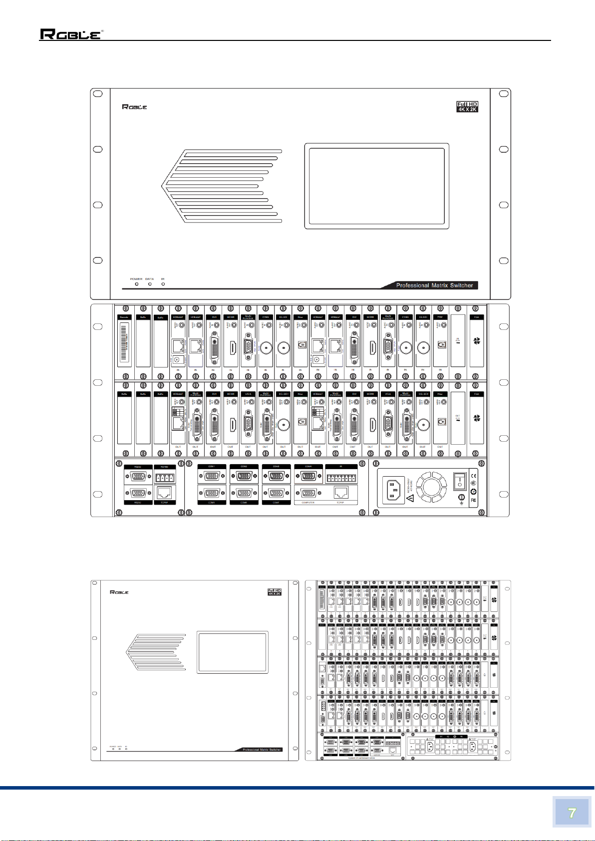
2. Features
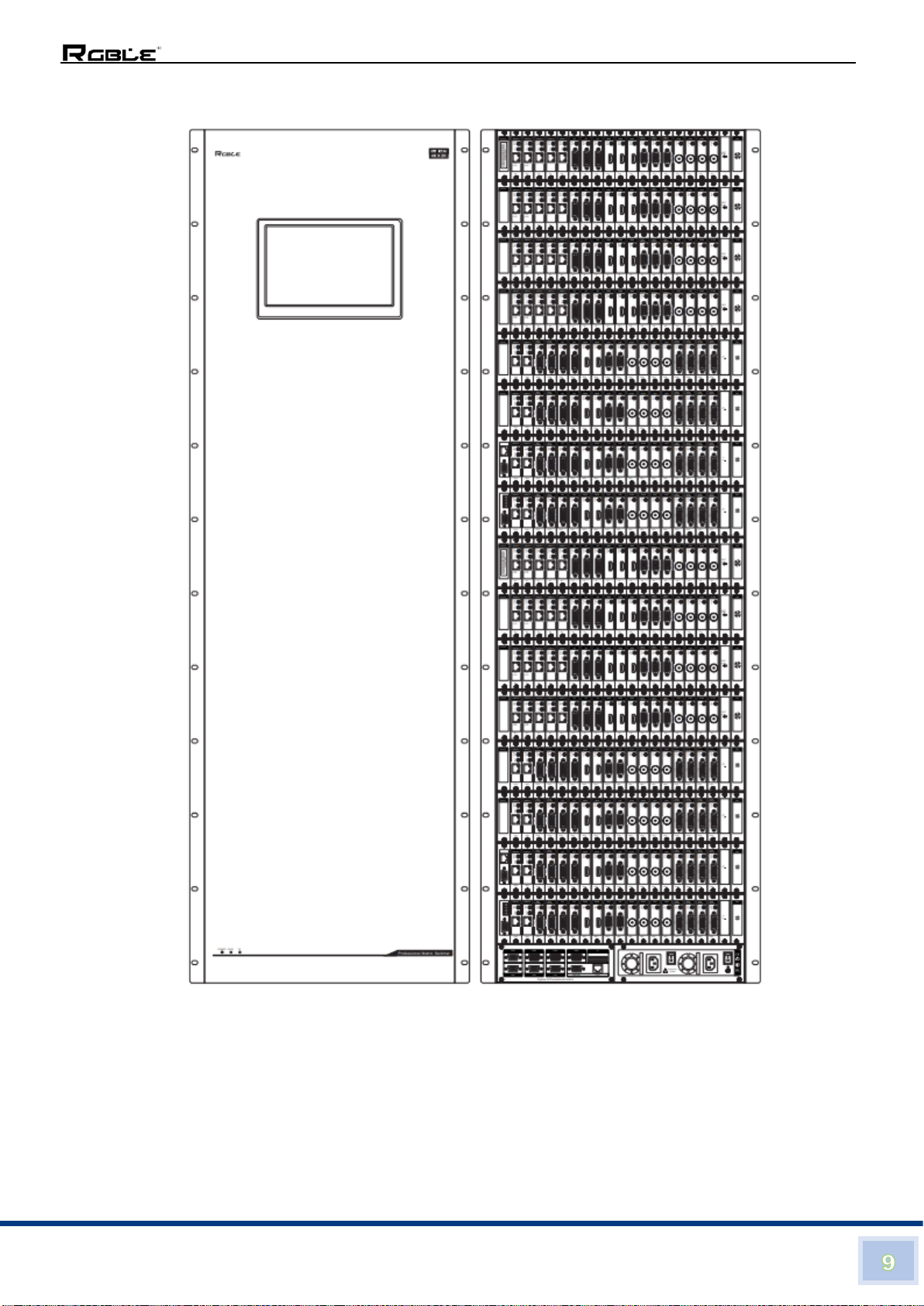
◼The matrix switcher available in I/O sizes: 8*8, 10*10, 16*16, 20*20, 36*36, 72*72, 144*144,
fully covers the industry applications.
◼Model range: MHD-88SK, MHD-1010S, MHD-1616SK, MHD-2020S, MHD-3636SK, MHD-
3636S, MHD-7272S and MHD-144144S, 8 Models of matrix switcher of touch screen series
and key LCD series.
◼With 4K telecommunication level digital chipsets, the host computer supports 4K*2K60 RGB
4:4:4 UHD uncompressed non-interference exchange
◼Supports HDMI 4K@60 and HDBT (RJ45) 4K@60 signals mixed in and out of various
interface formats
◼Supports CVBS, YPbPr, VGA, DVI, HDMI, 3G-SDI, Fiber, HDBT (RJ45) signals mixed in
and out of various interface formats
◼Single-link for single board module design: Independent data channel, connector, switching
channel, power supply system, effectively ensure that the signal pixel for pixel,

Stock Code 873117 en.rgble.com 400-1661-021
uncompressed, lossless, non-interference transmission and exchange inside the chassis,
At the same time, the matrix system is user-friendly for configuring, optimizing, upgrading
and maintaining
◼Hot-swappable—I/O cards, cooling fans and power supplies can be added or removed
without need of the power off. This is especially useful for mission-critical applications that
require continuous system operation.
◼Built-in 7 or 10-inch touch screen, software tool with a strong human-computer interaction
features and application settings:
A. Content preview function-the output image content is previewed before routing, safe
and efficient
B. Intelligently monitoring the input and output status, voltage, temperature, fan speed
C. Be able to set and apply directly to the resolution, refresh rate, format and EDID
related information on the touchscreen panel
◼High-speed floating point DSP(Digital Signal Processor)technology provides exceptional
switching speed, supports seamless fast switching, and improves the display performance
◼8-channel Central Control Module (Optional) to achieve wireless intelligent centralized
control of the system, expands the application
◼Audio loop out function: to support audio loop out function for input HDBT and HDMI signal,
support audio breakaway of HDMI output signal (Stereo), convenient to connect with the
sound reinforcement system;
◼Audio input function:DVI, VIDEO, VGA, YPbPr input Cards with audio input interface,
cooperate with the audio breakaway function of output cards—Provides the capability to
break away an audio signal from its corresponding video signal.
◼To be able to achieve audio and video synchronous switch without additional audio
switching equipment
◼Support for automatic EDID management, HDCP management, scenario presets and calls,
status queries and intelligent editing management functions
◼With the function of automatic save the power-off state and automatic memory recovery
when rebooting
◼Fully digital with RGB4:4:4 chroma sampling uncompressed for all signal channels
◼Server power supply:With large redundant power supply to meet the stable operation of
equipment in different occasions, detachable and convenient for maintenance
◼Professional cooling duct design:Independent plug-in fan cooling module, and controllable,
automatic, visual, high temperature alarm temperature control software guarantee
continuous working 24 hours a day 7 days a week.
◼Provides a variety of management styles:Touch screen management, RS232
management, network management and computer software management
◼Bidirectional RS-232 and IR insertion for AV device control —Bidirectional RS-232 control
and IR signals can be transmitted alongside the video signal, allowing the remote device to
be controlled without the need for additional cabling. Bidirectional control insertion
eliminates the need for control system wiring to remote devices.

Stock Code 873117 en.rgble.com 400-1661-021
3. Schematic Diagram
3.1 8 by 8 I/O Channels key LCD Interface
3.2 16 by 16 I/O Channels key LCD Interface

Stock Code 873117 en.rgble.com 400-1661-021
3.3 36 by 36 I/O Channels key LCD Interface
3.4 10 by 10 I/O Channels Touch Screen Interface

Stock Code 873117 en.rgble.com 400-1661-021
3.5 20 by 20 I/O Channels Touch Screen Interface
3.6 36 by 36 I/O Channels Touch Screen Interface

Stock Code 873117 en.rgble.com 400-1661-021
3.7 72 By 72 I/O Channels Touch Screen Interface

Stock Code 873117 en.rgble.com 400-1661-021
3.8 144 By 144 I/O Channels Touch Screen Interface

Stock Code 873117 en.rgble.com 400-1661-021
4 Operation Controls and Functions
4.1 Key LCD modules
4.1.1 Panel functions
Name
Function Description
Power LED
Indicates the status of power supply
LCD Display
Displays the operating interface
Navigation
Key
To select the required settings on the menu
OK Key
To apply a command
Input Key
Key 0-9, to select input channel numbers
Output Key
Key 0-9, to select output channel numbers
/ Key
To keep channel numbers apart
ALL Key
Widespread mode, i.e. all outputs are the same input signal
Figure 1, Front/Rear Panel

Stock Code 873117 en.rgble.com 400-1661-021
Back Key
To delete mistyping
Exit Key
To exit the current page and return to the home page
Main Control
Board
Provides TCP / Ip and RS 232 control interfaces
Input Board
Slot
To insert input cards
Output Board
Slot
To insert output cards
3 In 1 Power
Panel
Power Switch, fuse, 220V power socket
Earthing Bolt
Used for matrix external earthing
Cooling Fan
Module
Heat dissipation for I / O cards
4.1.2 Operations
4.1.2.1 Power up the switcher.
4.1.2.1.1 LCD screen displays, refer to
Figure 2, Main Menu.
4.1.2.1.2 Click Navigation key
▲▼◄► to select the icon
which you want, and the
selected icon box will be
highlighted in white.
4.1.2.1.3 Click OK key to enter to next
page.
4.1.2.2 Switching Operations
4.1.2.2.1 Select Switch icon, then Click
OK key
4.1.2.2.2 After entering the switching
page, there are three options:
audio-video switching,
audio switching only,
video switching only.
4.1.2.2.3 Click the Navigation keys to
select the above mentioned
three modes, refer to Figure
3, Switching.
(
Figure 2, Main Menu
Figure 3, Switching
Table1, Key LCD Function Description

Stock Code 873117 en.rgble.com 400-1661-021
)
4.1.2.2.4 When selected, Click the OK key to confirm.
4.1.2.2.5 Switching operation: This Matrix Supports 3 switching modes (1 in
to 1 out, 1 in to multi outs, and 1 in to all outs)
a) 1 In to 1 out, Click the corresponding input and output number
key, Click OK key, complete the switching operation.
b) When 1 in to multi outs, Click the corresponding input and
outputs channel keys, output numbers are separated by / key,
and then Click the OK key to complete the switch operation.
c) When 1 in to all outs, Click the corresponding input channel key,
then Click the All key, after completion Click the OK key to
complete the switching operation.
4.1.2.2.6 Click the Exit key to return to main menu.
4.1.2.3 Plan setting (refer to Figure 4)
Enter to the Plan setup page,
you can Save or Call the Plan.
Plan save (Save):
⚫Click the Navigation keys to
navigate to the location
where you want to save (you
can save plan in any of A, B,
C, D).
⚫Click the OK key to Save plan.
⚫Click the Exit key to return to main
menu.
Call the saved Plan (Call):
⚫Click the Navigation key to navigate to the plan location that
needs to be called (four scenarios A, B, C, and D can be called).
⚫Click the OK key to Call the plan.
⚫Click the Exit key to return to main menu.
4.1.2.4 Status Query (State) (refer to Figure 5)
⚫Click State key to enter to the Status Query Page
⚫Click the OK key to view the current configuration details.
⚫Click the Exit key to return to main menu.
Figure 4, Plan Setting
Figure 5, Status Query

Stock Code 873117 en.rgble.com 400-1661-021
4.1.2.5 The Resolution Setting (refer to Figure 6)
⚫Enter to the resolution settings page, Click the corresponding
channel keys, the top left corner of the page shows the selected
channel number
⚫Click the Navigation key to navigate to the desired resolution *
and Click Ok to set the resolution of the channel.
⚫Same for subsequent settings
⚫Click the Exit key to return to main menu.
*The resolution setting is only for the output scaler board, different board
has different resolution setting, please refer to the resolution setting
table.
4.1.2.6 Error Correction
In case of inputting setting error, click ►key to move the cursor to
the position to be modified, Click the Back key to delete the error,
re-input the right one.
Figure 6, Resolution Setting

Stock Code 873117 en.rgble.com 400-1661-021
4.2 Touch Control LCD panel
4.2.1 Panel functions
Name
Function Description
Power LED
Indicates the status of power supply
Data indicator
Indicates the communication data status of the central control module
IR Receiver
Indicates Infrared control of central control module
Touch
Control panel
Matrix setup and control (to wake up in-sleep screen please Click the
screen to resume display)
Input Board
Slot
Insert signal input board
Output Board
Slot
Insert signal output board
Figure 7, Front/Rear Panel

Stock Code 873117 en.rgble.com 400-1661-021
Cooling Fan
Module
Heat dissipation for I / O cards
Matrix RS232
Port
Local control and loop-out control of Matrix by computer
Matrix
TCP/IP Port
Computer-to-matrix remote control
Matrix RS485
Port
Computer-to-matrix local control (For Manufacturer only)
Central
Control
Module Slot
Insert central control module (optional)
AC power
socket
AC Power inlet
Power switch
Device power on or off
Earthing Bolt
Used for matrix external earthing
4.2.2 Operations (10 by 10 for example)
4.2.2.1 Power up the switcher
⚫LCD displays switching operation page by default
⚫4 Display Areas:
❶Status Display area: Display the operating temperature of the core chip
board and the working status of the cooling fan.
Figure 8, Switching Operation Page
Table 2, Touch LCD Function Description

Stock Code 873117 en.rgble.com 400-1661-021
❷Function selection area: Select the required operation function.
❸Channel Selection area: Key in the required input / output channel number
❹Setting display area: Display the result of the operation
4.2.2.2 Switching Operations (refer to Figure 9, Switching)
⚫After entering the switching page, there are three options:
audio-video switching, audio switching only, video
switching only.
(
)
⚫This Matrix Supports 3 switching modes (1 in to 1 out, 1 in to multi
outs, and 1 in to all outs)
a) 1 In to 1 out, Click the corresponding input and output
number key, Click Take key to complete the switching
operation.
b) When 1 in to multi outs, Click the corresponding input and
outputs channel keys, output numbers are separated by /
key, and then Click the Take key to complete the switch
operation.
c) When 1 in to all outs, Click the corresponding input channel
key, then Click the All key, after completion Click the Take
key to complete the switching operation.
4.2.2.3 Save settings (refer to Figure 10,Saving)
⚫To Save the input switching operation instructions, after the
completion of the setup, Click the Save key to enter the "Save
interface".
⚫Click the corresponding save location key to save in where you want,
(you can save plan in any of A, B, C, D).
⚫Click the Take Key to save the switching plan
⚫Click the Exit key to return to main menu.
Figure 9, Switching

Stock Code 873117 en.rgble.com 400-1661-021
4.2.2.4 Call the saved Plan (Call) (refer to Figure 10,Calling)
⚫Click the Call key to Go to the call screen
⚫Click on the letter key (A, B, C, D) to call the plan.
⚫Click the Take key to execute the switching command.
⚫Click the Exit key to return to main menu.
4.2.2.5 Status Query (State) (refer to Figure 11)
⚫Click State key to enter to the Status Query Page
⚫Clicking the Up/Down Key ▲▼on the right side of the page or
drag the Scroll Bar, you can view the current state of the
corresponding channel
⚫Click the Exit key to return to main menu.
Figure 10, Saving
Figure 11, Status Query

Stock Code 873117 en.rgble.com 400-1661-021
4.2.2.6 The Resolution Setup (refer to Figure 12)
⚫Click the Setup Key to go to the resolution settings page.
⚫Click the corresponding input or output channel number key
⚫Choose the desired resolution *
⚫Click Take key to set the resolution of the channel.
⚫Repeat the above process to finish all subsequent settings
⚫Click the Exit key to return to main menu.
* The resolution setting is only for the output scaler board, different
board has different resolution setting, please refer to the resolution
setting table.
4.2.2.7 Output Preview (refer to Figure 13)
⚫Click the Preview Key to enter to the Preview screen.
⚫Click the input channel number key that needs to be previewed.
⚫Click the Take key, the screen will flip to the output display.
⚫Tap the screen and return to the Preview screen.
⚫Click the Exit key to return to main menu.
Figure 12, Set the Resolution
Figure 13, Output Preview

Stock Code 873117 en.rgble.com 400-1661-021
5 RS232 TCP / IP Control
5.1 RS-232 communication port and connection methods
5.1.1 RS-232 communication port setting
Baud Rate
9600
Data Bit
8 Bit
Stop Bit
1 Bit
Parity Bit
No
Flow Control
No
5.1.2 RS-232 control interface
One channel of RS-232 serial interface is provided by the digital-analog HD multi
format Matrix Switcher, through which the Matrix is controlled. The RS-232 port is
the DB9 female, and the pins definition as follows:
Pin
Signal
Description
2
Tx
RS-232 protocol for transmitting data
3
Rx
RS-232 protocol for receiving data
5
GND
Signal earthing
5.1.3 RS-232 control interface and computer connection
Figure 14, RS-232 Pins
Figure 15, 5.1.3 RS-232 PC control connection
Table3, RS-232 port setting
Table 4, Pins definition
This manual suits for next models
7
Table of contents
Other RGBLE Matrix Switcher manuals