ABOUT YOUR WATER HEATER
5
GAS BOOSTING OPERATION
Water stored in the solar storage tank passes through the in-series gas booster when a hot tap is opened. The
in-series gas booster is for heating the water at times of low solar energy gain, such as during cloudy or rainy
weather, or during colder months.
Solar heated water can reach temperatures up to 75°C in the solar storage tank. When the solar heated water
temperature is 58°C or above, the in-series gas booster will not boost the water temperature. When the solar
heated water temperature is below 58°C, the gas burners ignite to provide immediate heating of the water to
its preset outlet temperature setting. The heat produced by the burner is transferred to the water through the
heat exchanger. The water is heated to a constant temperature by the automatic adjustment of the gas supply
to the burner to suit the water flow rate. The gas burners extinguish when the hot tap is closed.
If another type of in-series booster water heater is used and the solar heated water temperature is above its
thermostat setting, the water heater will not boost the water temperature. When the solar heated water
temperature is below the thermostat setting of the water heater, the booster will operate to heat the water.
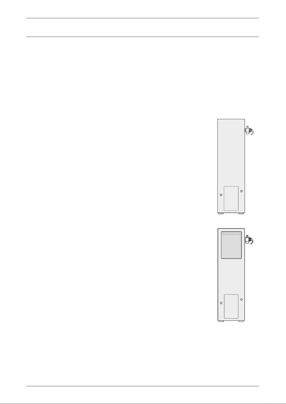
REDUCED HOT WATER FLOW WHEN HEAT EXCHANGER IS COLD
At a cold start-up, i.e. when the in-line gas booster has not operated for some time (which is most often first
thing in the morning), the initial flow of hot water may be reduced for a period of 5-10 seconds while the heat
exchanger warms up. This is both an energy and water saving feature of this water heater. Once the heat
exchanger has warmed up the hot water flow will increase and remain at normal flow levels. This feature will
only occur at a cold start-up and not when the heat exchanger is already warm from a recent use of hot water.
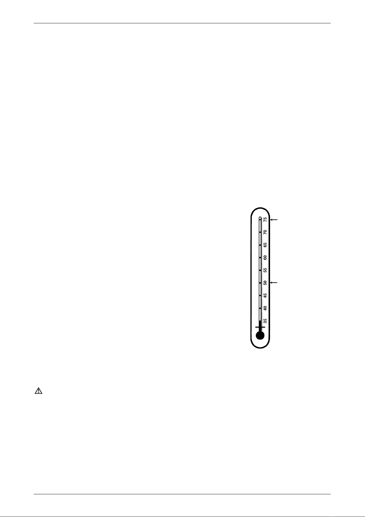
HOW HOT SHOULD THE WATER BE?
The solar control unit will circulate the closed circuit fluid through the solar
collectors until a temperature of approximately 75°C is reached in the solar
storage tank. During periods of low solar energy gain, the continuous flow
in-series gas booster will boost the water temperature automatically to its
preset outlet temperature setting, or to the temperature setting of another
type of in-series booster water heater.
The factory preset outlet temperature setting of the in-series gas booster is:
874820, 874826 60°C
Note: The preset outlet booster temperature setting of the continuous flow
in-series gas booster cannot be adjusted by the householder. The setting
can only be adjusted by the installer, Rheem Service or their nearest
Accredited Service Agent.
Note: AS 3498 requires that a water heater provides the means to inhibit the
growth of Legionella bacteria in potable water. If this water heater is installed
with an continuous flow in-series gas booster, then this requirement of
AS 3498 can be satisfied provided the booster is energised, its preset outlet
temperature setting is 70°C or higher and a remote temperature controller
or an EZiSET kit is not used.
If this water heater is installed with an in-series storage booster, then this requirement of AS 3498 can be
satisfied provided the storage booster is energised and its thermostat setting is 60°C or higher.
Warning: Temperature controllers or an EZiSET kit must not be fitted to the in-series booster as part of a
solar water heater system because water at a temperature much higher than the controller or EZiSET setting
can be delivered.
HOTTER WATER INCREASES THE RISK OF SCALD INJURY
This water heater can deliver water at temperatures which can cause scalding. Check the water temperature
before use, such as when entering a shower or filling a bath or basin, to ensure it is suitable for the application
and will not cause scald injury.
We recommend and it may also be required by regulations that an approved temperature limiting device be
fitted into the hot water pipe work to the bathroom and ensuite when this water heater is installed. This will
keep the water temperature below 50°C at the bathroom and ensuite. The risk of scald injury will be reduced
and still allow hotter water to the kitchen and laundry.
typical maximum
temperature from
solar gain
maximum
recommended supply
temperature to
bathrooms and
ensuites