RHEONICS SRV User manual

ATEX and IECEx Certified Sensors
Installation of Intrinsically Safe Sensors
Manual
Applicable to Rheonics Sensor Types: SRV, SRD, SRV-FPC, SRD-FPC
Certified ATEX and IECEx Viscometers and Density Meters
Product: SR Sensors - ATEX and IECEx certified
Rev 2.0 October 2020

Rheonics | Switzerland | U.S.A.
SRV, SRD, SRV-FPC, SRD-FPC Installation and Intrinsic Safety Manual P. 2
Version 2.0, Updated: October 29, 2020
Rheonics GmbH, Klosterstrasse 19, 8406 Winterthur, Switzerland
©Rheonics. Rheonics confidential and proprietary information.
GLOBAL SUPPORT
For Support, visit: https://support.rheonics.com
EUROPE HEADQUARTERS
Rheonics GmbH
Klosterstrasse. 19
8406 Winterthur Switzerland
Tel: +41 (0)52 511 32 00
US HEADQUARTERS
Rheonics, Inc.
3 Sugar Creek Center Blvd, Ste 100
Sugar Land, TX 77478
United States of America
Tel: +1 713 364 5472
Website: https://rheonics.com
Support Portal: https://support.rheonics.com
Sales E-Mail: info@rheonics.com
rheonics
© COPYRIGHT RHEONICS 2020
No part of this publication may be copied or distributed, transmitted, transcribed, stored in a
retrieval system, or translated into any human or computer language, in any form or by any
means, electronic, mechanical, manual, or otherwise, or disclosed to third parties without the
express written permission of Rheonics. The information contained in this manual is subject
to change without notice.
TRADEMARKS
Rheonics is a trademark of Rheonics, Inc. Other product and company names listed in this
manual are trademarks or trade names of their respective manufacturers.

Rheonics | Switzerland | U.S.A.
SRV, SRD, SRV-FPC, SRD-FPC Installation and Intrinsic Safety Manual P. 3
Version 2.0, Updated: October 29, 2020
Rheonics GmbH, Klosterstrasse 19, 8406 Winterthur, Switzerland
©Rheonics. Rheonics confidential and proprietary information.
Contents
1. Purpose of this manual ........................................................................................................................................5
2. Description of the sensors and general installation considerations ..................................................................5
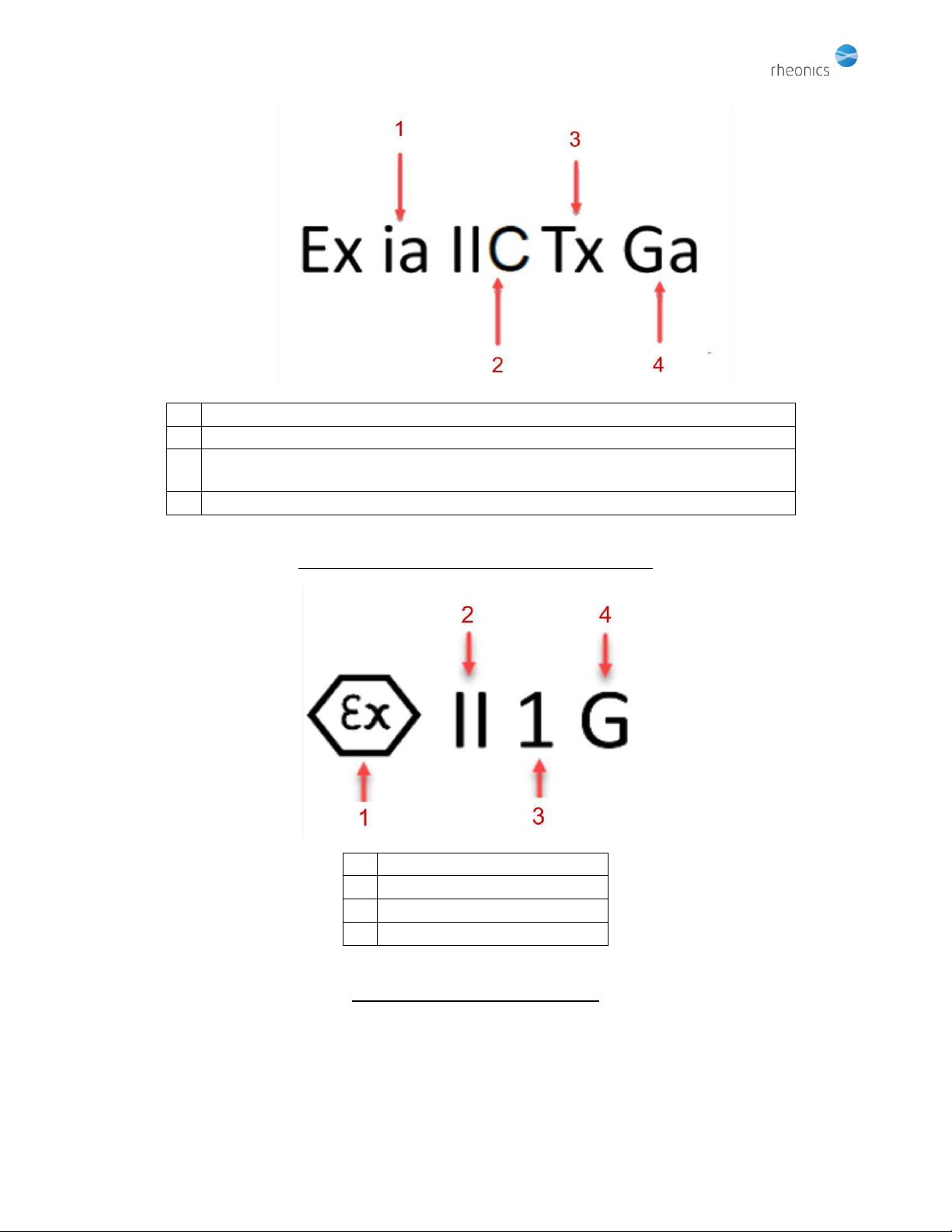
3. EX label description:.............................................................................................................................................7
3.1. General note on Category of protection and operating zone......................................................................9
3.2. Description of “X” conditions: operating conditions not described on the label, but that are necessary in
order to maintain intrinsic safety..............................................................................................................................9
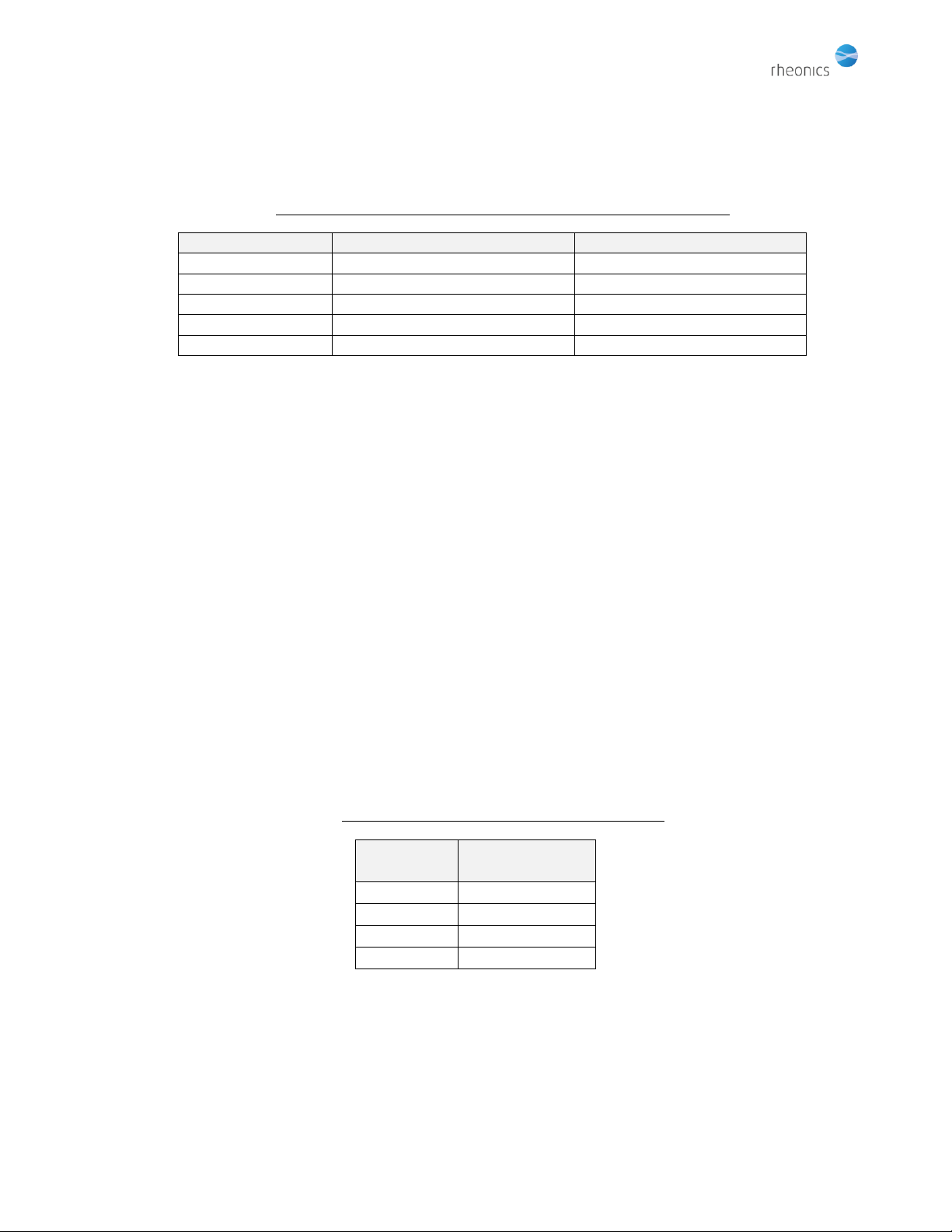
3.2.1. Area classification & Gas Grouping .....................................................................................................9
3.2.2. Electrical parameters relevant to intrinsic safety..............................................................................10
3.2.3. Temperature rating of the sensors according to T class ...................................................................10
3.2.4. Pressure rating of the sensors ...........................................................................................................11
3.2.5. Damage protection............................................................................................................................11
4. Safe use of ATEX approved equipment .............................................................................................................13
4.1. Notes on Safe Use of the ATEX Approved Equipment ...............................................................................13
4.2. Mounting, Commissioning, and Operation ................................................................................................13
5. Electrical Installation..........................................................................................................................................13
5.1. Cabling........................................................................................................................................................14
5.2. Zener diode barriers...................................................................................................................................18
5.3. Installation diagrams..................................................................................................................................20
5.4. Equipotential bonding................................................................................................................................25
5.4.1. Bonding/grounding conductor ..........................................................................................................25
5.4.2. Bonding to the sensor .......................................................................................................................26
5.4.3. Bonding configurations .....................................................................................................................27
6. Maintenance ...........................................................................................................................................................31
6.1. External Maintenance ......................................................................................................................................31
6.2. Sensor Maintenance.........................................................................................................................................31
6.3. Internal Maintenance.......................................................................................................................................31
7. Returning Equipment to the factory ......................................................................................................................31
8. Intrinsic safety certificates......................................................................................................................................32
9. Revisions and approvals .........................................................................................................................................32
English version of this manual is the only approved version from Rheonics and
installers should refer to it to confirm the correctness of information. In case of
any questions contact your local partner or Rheonics support.

Rheonics | Switzerland | U.S.A.
SRV, SRD, SRV-FPC, SRD-FPC Installation and Intrinsic Safety Manual P. 4
Version 2.0, Updated: October 29, 2020
Rheonics GmbH, Klosterstrasse 19, 8406 Winterthur, Switzerland
©Rheonics. Rheonics confidential and proprietary information.
Figures
Figure 1: Example of sensor labels identifying the markings ....................................................................... 7
Figure 2: IECEx Explosion classification description...................................................................................... 8
Figure 3: ATEX marking description..............................................................................................................8
Figure 4: SRV sensor with protective sleeve and impact shield mounted..................................................12
Figure 5: End view of SRV showing orientation of slot in impact shield..................................................... 12
Figure 6: Pinout of M12 connector with no Pt1000 installed.....................................................................15
Figure 7: Pinout of M12 connector with 4-wire Pt1000 connection ..........................................................16
Figure 8: Pinout of M12 connector with 3-wire Pt1000 connection ..........................................................17
Figure 9: Variant 1 - Wiring diagram with Pt1000 installed, 4-wire Pt1000 connection ............................22
Figure 10: Variant 2 - Wiring diagram with no Pt1000 installed.................................................................23
Figure 11: Variant 3 - Wiring diagram with Pt1000 installed, 3-wire Pt1000 connection ..........................24
Figure 12: Installation of grounding tab on SRV/SRD sensor......................................................................26
Figure 13: Several sensors grounded to common grounding point (“Star” topology) ............................... 28
Figure 14: Individual bonding of sensors to their Zener diode barriers .....................................................29
Figure 15: Hybrid, or multi-drop bonding...................................................................................................30
Tables
Table 1: EX-relevant electrical specification for SRV/SRD sensors .............................................................10
Table 2: Temperatures for gas ignition classes...........................................................................................10
Table 3: Sensor cable specifications ...........................................................................................................18
Table 4: Transducer coil circuit Zener diode barrier specifications............................................................ 18
Table 5: Pt1000 circuit(s) Zener diode barrier specifications .....................................................................19
Table 6: Specification of commercial Zener diode barrier suitable for transducer coil circuit ..................19
Table 7: Specification of commercial Zener diode barrier suitable for Pt1000 circuit(s) ........................... 19
Introduction
The operational conditions cited in this manual are essential to and pertain only to the maintenance
of intrinsic safety of the device. Operational conditions required for achieving the specified
measurement accuracy and operational factors not relevant to operation in explosive atmospheres
are given in the configuration data sheet supplied with the sensor. Please refer to the sensor
configuration data sheet before installing and operating the sensor.
This is a certified ATEX document. Changes must be approved by the Rheonics
EX Authorized Personnel.

Rheonics | Switzerland | U.S.A.
SRV, SRD, SRV-FPC, SRD-FPC Installation and Intrinsic Safety Manual P. 5
Version 2.0, Updated: October 29, 2020
Rheonics GmbH, Klosterstrasse 19, 8406 Winterthur, Switzerland
©Rheonics. Rheonics confidential and proprietary information.
ATTENTION: Installation in hazardous environment locations shall be
made in accordance with IECEx 60079-14 and other applicable codes
and standards.
1. Purpose of this manual
This manual contains information to enable the safe installation and operation of Rheonics SRV, SRV-
FPC, SRD and SRD-FPC sensors in areas that potentially contain explosive atmospheres. The manual is an
adjunct to the operation and configuration manual provided with the particular sensor to be installed. It
applies only to Rheonics SRV, SRV-FPC, SRD and SRD-FPC sensors labelled with the hexagonal ATEX
mark:
All other versions of Rheonics SRV/SRD sensors should NOT be considered safe to use in areas with
potential presence of explosive atmospheres.
2. Description of the sensors and general installation considerations
Rheonics SRV sensors are used to measure and control the viscosity of fluids, mainly under process
conditions. Rheonics SRD sensors measure, in addition, fluid density as well as true dynamic and
kinematic viscosity. Each sensor has a symmetric torsional resonator as its sensitive element. The effect
of the fluid in which it is immersed on its resonant response –its resonant frequency and damping –is
measured and interpreted by the electronics unit with which it is supplied.
Both of these devices, hereafter referred to collectively as “SR” sensors, are delivered in a version that is
intrinsically safe. That means that as long as the sensors are installed and operated as specified in this
manual, they are incapable of igniting explosive atmospheres in which they operate, provided they are
operated within the envelope of parameters described in this manual.
Each Rheonics SR sensor is delivered paired with an electronics unit that both operates the sensor and
transmits its measurement values over one of a variety of interfaces. The electronics unit is not itself
intrinsically safe. When operating Rheonics SR sensors in a hazardous area, one or more Zener diode
barriers must be installed between the Rheonics SR sensor and its electronics unit. This barrier serves to
limit the amount of current and voltage available to the sensor in case of a fault in its electronics unit
and/or within the sensor itself. The specifications for the required barriers are given in section 5.2
below.

Rheonics | Switzerland | U.S.A.
SRV, SRD, SRV-FPC, SRD-FPC Installation and Intrinsic Safety Manual P. 6
Version 2.0, Updated: October 29, 2020
Rheonics GmbH, Klosterstrasse 19, 8406 Winterthur, Switzerland
©Rheonics. Rheonics confidential and proprietary information.
Rheonics SR sensors are specified to maintain IP54 ingress protection under all operating conditions.
They are hermetically sealed in fully welded AISI 316L housings. Electrical connections are made through
a M12 connector whose contacts are hermetically sealed into a glass insulating disk.
The Zener diode barriers themselves must be situated either outside of any hazardous zone, or in the
zone specified by the manufacturers as safe for the barriers. The Rheonics SR sensor’s electronics unit
must be situated outside the hazardous zone.
Suitable cabling to safely connect the Rheonics SR sensor to its associated Zener barrier(s) is to be
provided by the installer. The minimum specification for the cabling in order to ensure intrinsic safety is
given in section 5.1.
Installation of Rheonics SR sensors must be performed by a qualified installer who is familiar with safe
installation practices for intrinsically safe equipment. In addition, the installer must be familiar with the
contents of this installation manual, to ensure that all conditions relevant to maintaining intrinsic safety
of the Rheonics SR sensors are met.
The following topics are covered in the next sections:
•Description of the label as it defines the safe operating parameters of the sensor
•Discussion of limits on specific operating parameters of the Rheonics SR sensors not explicitly
listed on the label, but as indicated by the symbol “X” following the ATEX and IECEx certificate
numbers.
Specification of the Zener diode barrier(s) to ensure safe operation of the Rheonics SR sensors,
as well as specific recommendations for commercially available barriers for use with the
Rheonics SR sensors.

Rheonics | Switzerland | U.S.A.
SRV, SRD, SRV-FPC, SRD-FPC Installation and Intrinsic Safety Manual P. 7
Version 2.0, Updated: October 29, 2020
Rheonics GmbH, Klosterstrasse 19, 8406 Winterthur, Switzerland
©Rheonics. Rheonics confidential and proprietary information.
3. EX label description:
Old label
New label
1
CE mark Notified body: TÜV Rheinland
2
ATEX Marking
3
Explosion classification
4
IECEx certificate number with appended “X”
5
ATEX certificate number with appended “X”
6
Sensor
7
Identification Number
8
Sensor Manufacturer
9
See below for “Tx” and “X” conditions for explosion - classification and certificates
Figure 1: Example of sensor labels identifying the markings

Rheonics | Switzerland | U.S.A.
SRV, SRD, SRV-FPC, SRD-FPC Installation and Intrinsic Safety Manual P. 8
Version 2.0, Updated: October 29, 2020
Rheonics GmbH, Klosterstrasse 19, 8406 Winterthur, Switzerland
©Rheonics. Rheonics confidential and proprietary information.
1
Intrinsically safe
2
Safe for gas groups IIA, IIB and IIC
3
Ignition temperature classes that define ambient/fluid temperature range, as
given in table below
4
Equipment protection level = very high
Figure 2: IECEx Explosion classification description
1
ATEX Mark
2
Non-mining equipment
3
Category 1 (Zone 0)
4
For gases
Figure 3: ATEX marking description

Rheonics | Switzerland | U.S.A.
SRV, SRD, SRV-FPC, SRD-FPC Installation and Intrinsic Safety Manual P. 9
Version 2.0, Updated: October 29, 2020
Rheonics GmbH, Klosterstrasse 19, 8406 Winterthur, Switzerland
©Rheonics. Rheonics confidential and proprietary information.
3.1. General note on Category of protection and operating zone
3.2. Description of “X” conditions: operating conditions not described on the
label, but that are necessary in order to maintain intrinsic safety
Certain operating conditions must be met in order to ensure that the sensors and their
associated Zener diode barriers meet intrinsic safety criteria. These include:
•Electrical parameters
•Operating temperature ranges
•Safe hydrostatic pressure limits
•Maintenance of ingress protection
•Protection against mechanical impact
•Protection against solid materials transported by fluid being monitored
3.2.1. Area classification & Gas Grouping
Area classification
Zone 1
Area in which an explosive gas atmosphere is likely to occur in
normal operation occasionally
Zone 2
Area in which an explosive gas atmosphere is not likely to occur in
normal operation and if it does occur, is likely to do so only
infrequently and will exist for a short period only
Zone 21
Place in which an explosive atmosphere in the form of a cloud of
combustible dust in air is likely to occur in normal operation
occasionally
Zone 22
Place in which an explosive atmosphere in the form of a cloud of
combustible dust in air is not likely to occur in normal operation but,
if it does, will persist for a short period only
Gas Grouping
Group IIA
Propane
Group IIB
Ethylene
Group IIC
Hydrogen and Acetylene
Although the sensors are specified for Category 1 (hazardous Zone 0), they may also be used
for Categories 2 and 3 (Zones 1 and 2). However, if the sensor has been used in a Category 3
(Zone 2) installation, it is no longer safe to use in categories 1 and 2 (Zones 0 and 1), because
of the risk that the sensor has been damaged. It is the responsibility of the installer and the
end user to ensure that any Rheonics SRV or SRD sensor that has been used in a Category 2
installation is not re-used for Category 1 or 2 installations.

Rheonics | Switzerland | U.S.A.
SRV, SRD, SRV-FPC, SRD-FPC Installation and Intrinsic Safety Manual P. 10
Version 2.0, Updated: October 29, 2020
Rheonics GmbH, Klosterstrasse 19, 8406 Winterthur, Switzerland
©Rheonics. Rheonics confidential and proprietary information.
3.2.2.Electrical parameters relevant to intrinsic safety
Table 1: EX-relevant electrical specification for SRV/SRD sensors
Parameter
RTD (Pt1000) circuit
Transducer coil circuit
Ui
9V
7.3V
Ii
5 mA
730mA
Pi
41 mW
1.3W
Ci
negligible
negligible
Li
negligible
<44µH
The two circuits are considered independent because they are electrically isolated from one
another.
3.2.3.Temperature rating of the sensors according to T class
The following temperature class table shows the range of ignition temperature classes for which
the sensors are specified, together with the ambient operational temperature for each class,
where Ta is the lesser of the process fluid temperature and the ambient temperature
surrounding the portion of the sensor outside of the process fluid. In typical applications, the
fluid temperature will be equal to or greater than the ambient temperature, so it will determine
the temperature class. The symbol “Tx” refers to the corresponding symbol on the sensor EX
label. It refers to the temperature classes listed on the following Table 2. However, the user
must be aware that these temperatures only show the limits for safe operation of the sensor in
different explosive atmospheres. The actual temperature range over which the sensor will
function accurately and without functional damage is shown on the individual configuration data
sheet provided with each sensor.
Table 2: Temperatures for gas ignition classes
Tx
(T class)
Ta
T6
-
T5
-
T4
-
T3
-85°C

Rheonics | Switzerland | U.S.A.
SRV, SRD, SRV-FPC, SRD-FPC Installation and Intrinsic Safety Manual P. 11
Version 2.0, Updated: October 29, 2020
Rheonics GmbH, Klosterstrasse 19, 8406 Winterthur, Switzerland
©Rheonics. Rheonics confidential and proprietary information.
3.2.4.Pressure rating of the sensors
The SR sensors are provided in two variants that have different pressure ratings. All variants
except for the “FPC” or fixed process connection SRV and SRD sensors are rated for a maximum
hydrostatic pressure of the process fluid of 700 bar (10,000 PSI) in order to retain IP54 ingress
protection as relevant for the sensor’s intrinsic safety. The SRV/SRD “FPC” sensors have a
maximum fluid pressure rating of 70 bar (1,000 PSI).
These pressure ratings pertain only to maintenance of intrinsic safety of the sensors. Please
consult the configuration data sheet delivered with the particular sensor for pressure limits for
maintenance of accuracy and operational safety.
3.2.5.Damage protection
Rheonics SRV/SRD sensors are provided with an impact shield to protect the back end of the
sensor from mechanical damage that could compromise IP54 ingress protection. The impact
shield must be installed whenever the surrounding equipment permits it. If there is insufficient
space to install the impact shield, the sensor must be protected from mechanical impact (as
from falling objects) by the surrounding equipment. In all cases, it is the responsibility of the
installer to ensure that the sensor cannot be impacted by falling objects or other sources of
mechanical impact. The shield is installed by sliding the end of the shield over the back end of
the sensor, up to at least the weld line on the sensor body. It must extend far enough toward
the back so that it completely covers the M12 connector that connects the sensor cable to the
sensor. The worm-drive screw is then tightened so that the shield securely grips the back end of
the sensor housing.
Rheonics SRV/SRD sensors are also provided with a protective sleeve that shields the immersed
end of the sensor from impact by large objects in the fluid flowing over it that could damage the
sensor and lead to fluid penetration. Although the sensor is very robust, the sleeve must be
installed whenever there are solid objects in the fluid larger than 8mm in their smallest
dimension. The protective sleeve is attached by sliding it over the neck of the sensor as far as it
will go, and then tightening the set screws around its periphery.
The following Figures 4 and 5 show the correct method for installing both the impact shield and
the protective sleeve:

Rheonics | Switzerland | U.S.A.
SRV, SRD, SRV-FPC, SRD-FPC Installation and Intrinsic Safety Manual P. 12
Version 2.0, Updated: October 29, 2020
Rheonics GmbH, Klosterstrasse 19, 8406 Winterthur, Switzerland
©Rheonics. Rheonics confidential and proprietary information.
1
Slots in protective sleeve exclude any fluid-borne particles larger than 8 mm diameter
2
Protective shield
3
Impact shield
Figure 4: SRV sensor with protective sleeve and impact shield mounted
1
Impact shield
2
Impact shield must be installed so that slot in shield is facing down
Figure 5: End view of SRV showing orientation of slot in impact shield
ATTENTION: These parameters and conditions must be adhered to.
If not, injury may be caused to person or property.

Rheonics | Switzerland | U.S.A.
SRV, SRD, SRV-FPC, SRD-FPC Installation and Intrinsic Safety Manual P. 13
Version 2.0, Updated: October 29, 2020
Rheonics GmbH, Klosterstrasse 19, 8406 Winterthur, Switzerland
©Rheonics. Rheonics confidential and proprietary information.
4. Safe use of ATEX approved equipment
4.1. Notes on Safe Use of the ATEX Approved Equipment
Approved usage of the meter is restricted to fluids compatible with the wetted materials of the
flow meter and within the restrictions on temperature and pressure as defined in the product
manual.
4.2. Mounting, Commissioning, and Operation
The device has been designed to operate safely in accordance with the current technical and
safety regulations of the EU. If installed incorrectly or used for applications for which it is not
intended, it is possible that application related changes may arise. For this reason, the instrument
must be installed, connected, operated, and maintained according to the instructions in this and
the specific product operating manual.
Persons handling/installing or commissioning this equipment must be authorized and suitably
qualified. The manual must be read, understood, and the instructions must be followed.
Modifications and repairs to the device are only permissible when they are expressly approved in
this manual.
5. Electrical Installation
ATTENTION: Substitution of components may impair intrinsic
safety.
Installation of the sensors must be carried out according to the instructions and diagrams in this section.
Sensors installed in this manner will become part of an intrinsically safe system that will be incapable of
igniting explosive gas atmospheres as specified on the sensor label and additional specifications in the
preceding section 3above.
There are four basic considerations that govern the electrical installation of the sensor. They are:
•Cabling
oSelection of a suitable cable
oWiring of the cable to a suitable sensor-side connector
oWiring of the cable to the Zener diode barrier(s) associated with the system.

Rheonics | Switzerland | U.S.A.
SRV, SRD, SRV-FPC, SRD-FPC Installation and Intrinsic Safety Manual P. 14
Version 2.0, Updated: October 29, 2020
Rheonics GmbH, Klosterstrasse 19, 8406 Winterthur, Switzerland
©Rheonics. Rheonics confidential and proprietary information.
•Selection / identification of wiring scheme depending on intended Pt1000 temperature sensor
connection
oSensor with 4-wire Pt1000 connection
▪3 Zener diode barriers required
▪Highest accuracy
▪Uses standard sensor
oSensor with 3-wire Pt1000 connection
▪2 Zener diode barriers required
▪Lower accuracy than 4-wire Pt1000 connection
▪Uses standard sensor
▪May require temperature calibration for best accuracy
oSensor with no Pt1000 sensor
▪1 Zener diode barrier required
▪Uses special sensor with no Pt1000 installed
▪Temperature may be measured with external temperature sensor
▪Possibility of temperature estimation without external sensor. Please consult
Rheonics for more information regarding accuracy.
•Zener diode barrier selection
oUsing Zener diode barriers recommended in this manual
oUsing alternative Zener diode barriers that meet the specifications given in this manual.
•Equipotential bonding method selection
oUsing cable shield for equipotential bonding
oUsing separate bonding conductor
▪Different schemes possible depending on requirements of system layout
5.1. Cabling
The SRV/SRD sensor is connected to its associated Zener diode barriers by means of a cable that
has an 8 pole M12 connector on the sensor end. The end that connects to the Zener diode
barrier must be provided with crimped conductor-end sleeves, which are held by screw clamps
on the Zener diode barriers. Appropriate cabling must conform to the following specifications:
Electrical connections to the M12 connector depend on the presence or absence of the Pt1000,
and in its presence, whether a 3-wire or a 4-wire connection has been selected. For a
connection with no Pt1000, the pins are assigned as in Fig. 6:

Rheonics | Switzerland | U.S.A.
SRV, SRD, SRV-FPC, SRD-FPC Installation and Intrinsic Safety Manual P. 15
Version 2.0, Updated: October 29, 2020
Rheonics GmbH, Klosterstrasse 19, 8406 Winterthur, Switzerland
©Rheonics. Rheonics confidential and proprietary information.
1
1: Transducer coil +
2
2: Transducer coil -
3
3: No connect
4
4: No connect
5
5: No connect
6
6: No connect
7
7: No connect
8
8: No connect
9
Signal assignment version without Pt1000
M12 connector front view
Figure 6: Pinout of M12 connector with no Pt1000 installed
For a connection with 4 wires, the pinout is shown in Fig. 7 below:

Rheonics | Switzerland | U.S.A.
SRV, SRD, SRV-FPC, SRD-FPC Installation and Intrinsic Safety Manual P. 16
Version 2.0, Updated: October 29, 2020
Rheonics GmbH, Klosterstrasse 19, 8406 Winterthur, Switzerland
©Rheonics. Rheonics confidential and proprietary information.
1
1: Transducer coil +
2
2: Transducer coil -
3
3: No connect
4
4: No connect
5
5: Pt1000 Sens +
6
6: Pt1000 Sens -
7
7: Pt1000 I +
8
8: Pt1000 I -
9
Signal assignment Pt1000 4-wire version
M12 connector front view
Figure 7: Pinout of M12 connector with 4-wire Pt1000 connection
For a connection with 3 wires, the pinout in Fig. 8 is used:

Rheonics | Switzerland | U.S.A.
SRV, SRD, SRV-FPC, SRD-FPC Installation and Intrinsic Safety Manual P. 17
Version 2.0, Updated: October 29, 2020
Rheonics GmbH, Klosterstrasse 19, 8406 Winterthur, Switzerland
©Rheonics. Rheonics confidential and proprietary information.
1
1: Transducer coil +
2
2: Transducer coil -
3
3: No connect
4
4: No connect
5
5: Pt1000 Sens +
6
6: Pt1000 Gnd
7
7: Pt1000 I +
8
8: No connect
9
Signal assignment Pt1000 3-wire version
M12 connector front view
Figure 8: Pinout of M12 connector with 3-wire Pt1000 connection
In addition, the M12 connector must be rated at IP54 or higher.
Detailed pinout and connection diagrams are given in section 5.3 below.
The cable and connector selected must be rated for at least the highest ambient temperature at
which the sensor will be used. They must meet the following specifications:

Rheonics | Switzerland | U.S.A.
SRV, SRD, SRV-FPC, SRD-FPC Installation and Intrinsic Safety Manual P. 18
Version 2.0, Updated: October 29, 2020
Rheonics GmbH, Klosterstrasse 19, 8406 Winterthur, Switzerland
©Rheonics. Rheonics confidential and proprietary information.
Table 3: Sensor cable specifications
Parameter
Value
Minimum ingress protection (cable + connector)
IP54
Connector
M12 8 pole, A-coded, female, IP54
Twisted pair cable with a shield
4x2, shielded cable with 4 twisted pairs
Maximum length
500 m.
Minimum required conductor cross section
0.25 mm2
Maximum practical cross section
0.5 mm2
Maximum inductance
1.5 mH/km, per conductor
Maximum capacitance, conductor-to-conductor
220nF/km
Maximum capacitance, wire to shield
300nF/km
A commercial cable that satisfies the preceding specification is Helu Kabel type OB-BL-PAAR-CY
4x2x0.5mm2.
5.2. Zener diode barriers
Each SRV/SRD must be connected to its electronics unit through Zener diode barriers as
appropriate to the installation. There are several different connection options, depending on
whether or not the SRV/SRD has a built-in Pt1000, and if so, how the Pt1000 is connected (4 or 3
wire connection). The diagrams in section below show these options.
In addition to the proper connection, the Zener diode barriers need to fulfill the electrical
specifications shown in the following tables.
The Zener diode barrier connected to the transducer coil circuit must meet the following
specifications:
Table 4: Transducer coil circuit Zener diode barrier specifications
Max. output voltage
Uo
< 7.3
V
Min. series resistance
Ro
> 9.8
Ohm
Max. output current
Io
< 730
mA
Max. output power
Po
< 1.3
W
Fuse rating
<=200
mA
This Zener diode barrier must have two channels, one for each conductor of the transducer coil
circuit.
If the Pt1000 is present in the sensor, it must be connected to one or two Zener diode barriers
with the following specification, each with two channels:

Rheonics | Switzerland | U.S.A.
SRV, SRD, SRV-FPC, SRD-FPC Installation and Intrinsic Safety Manual P. 19
Version 2.0, Updated: October 29, 2020
Rheonics GmbH, Klosterstrasse 19, 8406 Winterthur, Switzerland
©Rheonics. Rheonics confidential and proprietary information.
Table 5: Pt1000 circuit(s) Zener diode barrier specifications
Max. output voltage
Uo
< 9
V
Min. output resistance
Ro
> 1950
Ohm
Max. output current
Io
< 5
mA
Max. output power
Po
< 10
mW
Fuse rating
<=80
mA
For a 3-wire connection, a single barrier may be used, with the third (grounding) lead of the
Pt1000 circuit connected to ground through the cable shield. For a 4-wire connection, two Zener
diode barriers must be used, with two wire connected to each of the two channels of the Zener
diode barriers.
The Zener diode barriers must be located outside of the hazardous zone, or in a zone allowed by
the manufacturer’s specification. They must be properly grounded.
Commercial Zener diode barriers that fulfill these specifications are:
For transducer coil circuit:
Pepperl + Fuchs Z757
Table 6: Specification of commercial Zener diode barrier suitable for transducer coil circuit
Series resistance
9.8 ohms, min.
Fuse rating
200 mA
Maximum safe voltage
250 V
Output voltage, Uo
7.14 V
Output current, Io
729 mA
Output power, Po
1.3W
For Pt1000 circuits (1 or 2 units depending on whether 3 or 4 wire connections are used):
Pepperl + Fuchs Z041
Table 7: Specification of commercial Zener diode barrier suitable for Pt1000 circuit(s)
Series resistance
1957 ohms, min.
Fuse rating
80 mA
Maximum safe voltage
250 V
Output voltage, Uo
8.61 V
Output current, Io
4 mA
Output power, Po
9.4 mW

Rheonics | Switzerland | U.S.A.
SRV, SRD, SRV-FPC, SRD-FPC Installation and Intrinsic Safety Manual P. 20
Version 2.0, Updated: October 29, 2020
Rheonics GmbH, Klosterstrasse 19, 8406 Winterthur, Switzerland
©Rheonics. Rheonics confidential and proprietary information.
5.3. Installation diagrams
The following diagrams show how the sensors, their cables and the associated Zener diode
barriers must be connected in order to ensure intrinsic safety of the entire system.
The selected connection method depends on the configuration of the sensor, as well as the
choice of temperature measurement connection.
For all variants, the following rules must be followed:
The cable shield must be connected to one of the sensor-side grounding terminals of the Zener
diode barrier associated with the transducer coil circuit. In the following circuit examples, this is
the Pepperl + Fuchs Z757 Zener diode barrier. The cable shield should be connected to either
terminal 2 or 3 of the Zener diode barrier.
The Zener diode barrier(s) must be grounded to a known-reliable earth ground. It is the
responsibility of the installer to ensure the quality and reliability of the selected ground point.
Zener diode barriers are delivered with installation instructions that include information about
grounding methods. Zener diode barriers that are mounted on DIN rails generally have
grounding mechanisms that engage with the rails, which themselves must then be tied to a
known-reliable grounding point. It is the responsibility of the installer to ensure that the Zener
diode barriers are properly and reliably grounded according to the manufacturer’s
specifications.
In the event that more than one sensor is used in a system, the decision of how to bond the
sensors to a grounding point depends on the layout of the system. One of the configurations
shown in section 5.4.3 below may be used, depending on which is the most convenient. In the
given examples, a system with three sensors is shown, although larger printing applications may
have 10 or more sensors installed on a single machine.
First, we consider different wiring configurations for alternative Pt1000 temperature sensor
connections.
Variant 1: Standard sensor with Pt1000 temperature element installed in the sensor tip. 4-wire
connection of the Pt1000 circuit to the electronics unit. 2 Zener diode barriers with 2 channels
each are required for the Pt1000 circuit. A single 2-channel Zener diode barrier is required for
the sensor coil circuit. This configuration provides the highest temperature accuracy, but
requires two Zener diode barriers for connection.
Variant 2: Special sensor with no Pt1000 temperature element installed. No Zener diode barriers
are required for the Pt1000 circuit. A single 2-channel Zener diode barrier is required for the coil
circuit.
Variant 3: Standard sensor with Pt1000 installed, with 3-wire connection to the electronics unit.
A single 2-channel Zener diode barrier is required for the Pt1000 circuit. A single 2-channel
Zener diode barrier is required for the coil circuit. The advantage of this circuit is that one less
This manual suits for next models
3
Table of contents
Other RHEONICS Accessories manuals