RHEONIK RHE 07 User manual

REV. L October 2014
Rheonik Messtechnik GmbH reserves the rightto make changes without notice at any time
Operation Manual
RHEONIK
Coriolis Flowmeter
RHE 07, 08, 11
RHM .. NT, ETx, HT
RHEONIK the Coriolis Flowmeter experts

Rheonik Messtechnik REV. L October 2014
.
RHEONIK Coriolis Flowmeter Operation Manual RHE 07, 08, 11 Page 2
TABLE OF CONTENTS Page
Important safety instructions 4
Installation Quick Guide 5
1. Installation and operation instructions
1.1. General system description 6
1.2. Installation instructions for sensor RHM 6
1.3. Wiring sensor RHM 9
1.4. Mounting instructions RHE flow transmitter 11
1.5. Power supply wiring 11
1.6. Safety instructions for electrical connection 11
2. Operating and programming
2.1. General instructions 12
2.1.1. Keyboard and display 12
2.1.2. Basic operating and programming principle 13
2.1.3. Basic functions
2.1.3.1. Zero calibration 14
2.1.3.2. Reset totalizer 15
2.1.3.3. Display units 15
2.1.3.4. Display sequence and format 16
2.1.3.5. Inputs and outputs
2.1.3.5.1. Current outputs #1 and #2 (analog) 17
2.1.3.5.2. Analog inputs 18
2.1.3.6. Digital inputs and outputs
2.1.3.6.1. Frequency output 19
2.1.3.6.2. Serial communication (interface connection) 20
2.1.3.6.3. External contact inputs 21
2.1.3.6.4. Contact outputs 22
2.1.3.6.5. Configuration of the digital outputs 23
2.1.4. Advanced setup and diagnostics
2.1.4.1. Diagnostics menu 24
2.1.4.1.1. Sensor diagnostics 24
2.1.4.1.2. Sensor basic level programming (BASIS SETUP) 25
3. Error codes 28
4. Warnings 30
5. Troubleshooting guide
5.1. Sensor voltages and resistances 30
5.2. Temperature calibration 32

Rheonik Messtechnik REV. L October 2014
.
RHEONIK Coriolis Flowmeter Operation Manual RHE 07, 08, 11 Page 3
TABLE OF CONTENTS continued Page
6. Option batch function
6.1. Introduction 33
6.2. Remote electronic RHE 07/08/11 batch menu 33
6.3. Optioncode selection 34
6.4. Examples with explanation 35
6.5. Serial interface and batch option 35
7. Replacement parts 36
A-P-P-E-N-D-I-X:
Wiring diagram; RHMxx, RHE 07, 07c, 08, 11
Wiring diagram; RHE15 and RHE 07, 07c, 08, 11
Wiring diagram; RHMxx with free cable ends
Batch Menu
RHE basic level user menu
RHE service and diagnostic level menu
Ex-Safety Instructions
EC – Declaration of Conformity

Rheonik Messtechnik REV. L October 2014
.
RHEONIK Coriolis Flowmeter Operation Manual RHE 07, 08, 11 Page 4
Important safety instructions for the operation of Coriolis Flowmeters
The following safety guidelines must be adhered to.
The operation of equipment in hazardous-areas (with danger of explosion) must be
carried out under adherence to the specific local guidelines.
The flow meters are produced for different types of use according to international
standards. The operation conditions of the equipment are identified on the name-
plate and must be adhered to.
The indicated limits for ambient- and medium temperature must be maintained.
Rapid temperature changes inside the sensor due to the measuring medium must be
avoided. Please note the references in the manual.
The maximum permitted working pressure must not be exceeded.
Especially piston pumps can produce considerable pressure peaks.
Please note, that abrasive media can reduce the wall thickness of the measuring
pipes and thus also reduce the maximum operating pressure.
The construction material which comes in contact with the medium is identified on
the name-plate.
The manufacturer accepts no responsibility for the measuring instruments with re-
spect to the medium to be measured.
We recommend checking the wall thickness of the measuring tubes from time to
time, should there be any doubts about the corrosion resistance of the materials in
touch with the medium
Rheonik does not assume any liability for production-stops and or consequential
losses if this is not particularly agreed on.
Furthermore, please note, that our devices shall not be used in life-preserving facili-
ties in medical facilities, in utility vehicle, aircraft and water vehicles or in mining ac-
tivities.
The installation of the RHE07c requires that the customer connection between
RHE07c and customer’s monitoring equipment must not exceed 30m.

Rheonik Messtechnik REV. L October 2014
.
RHEONIK Coriolis Flowmeter Operation Manual RHE 07, 08, 11 Page 5
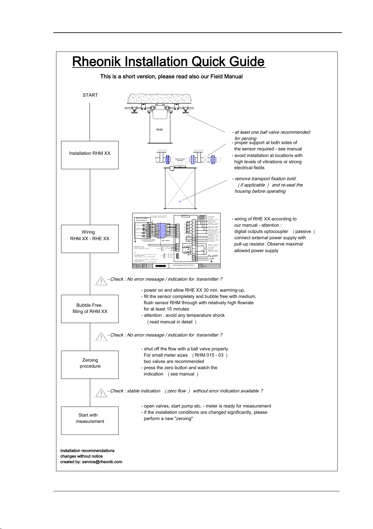
This is a short version, please read also our Field Manual
Z. - Nr.
Blatt
Projekt
E08W-E
1 / 1
Gepr.
von
Datum
Erstellt :08.08.2001Kunde
Gepr.
Bearb.
Datum
Änderung :
H.G.Rudolph
M.Küppers
RHE 08-
+
17
18
19
20
21
27
26
23
23
15
16
25
-
+
24
2,7 K
2,7 K
-+
-+
13
987654 2
Wiring diagramm RHE 08 standard
External intrinsically safe
zeroing contact
︵
option
︶
, is
subject of a separate EEx - certificate.
common connection
︵
0 Volt
︶
for frequency / pulses and
digital outputs 1 to 3
digital output 3
︵
passive
︶
function programmable
digital output 2
︵
passive
︶
function programmable
digital output 1
︵
passive
︶
function programmable
digital output
︵
passive
︶
for mass flow rate
frequency / pulses
external voltage
max. 30 VDC
analog output 1
︵
active
︶
current loop : 0/4 - 20 mA
max. 1000 Ohm
analog output 2
︵
active
︶
current loop : 0/4 - 20 mA
max. 1000 Ohm
digital input 2
︵
passive
︶
function programmable
external voltage
max. 30 VDC
digital input 1
︵
passive
︶
function programmable
Note :
EEx - version : In - and outputs
︵
connectors 15 to 27
︶
are galvanically isolated.
Sensor connections
︵
1 to 9
︶
are intrinsically safe.
Not EEx - version : In - and outputs
︵
connectors 15 to 27
︶
are galvanically isolated.
Sensor connections
︵
1 to 9
︶
are not intrinsically safe.
Drive coils
Temperature
Sensor PT100
Mass Flow Meter
Sensor RHM xx
current
︵
open collector
︶
max. 50 mA !
Pick-up coil 1
Pick-up coil 2
Screen to ground connection ONLY with
HT- SENSORS
︵
High Temperature
︶
!
︵
only with option EEx !
︶
123456789
10
11
Intrinsically safe only for EEx - version
24 VDC115/ 230 VAC
12
13
14
HAZARDOUS AREASAFE AREA
Source
︵
5 VDC
︶
Sens
︵
max. 5 VDC
︶
Ground
Aux. Input
-
+
PE
29
28
30
NL1
12345
6789
RS 422 male 9 Pin
TD+ > RD+ Pin 4
RD+ < TD+ Pin 2
TD - > RD - Pin 7
RD - < TD - Pin 9
Host
- Check : No error message / indication for transmitter ?
- Check : stable indication
︵
zero flow
︶
without error indication available ?
Installation recommendations
changes without notice
created by: service@rheonik.com
RHM
Rheonik Installation Quick Guide
Installation RHM XX
Wiring
RHM XX - RHE XX
START
Start with
measurement
Bubble Free
filling of RHM XX
Zeroing
procedure
- power on and allow RHE XX 30 min. warming-up.
- fill the sensor completely and bubble free with medium,
flush sensor RHM through with relatively high flowrate
for at least 15 minutes
- attention : avoid any temperature shock
︵
read manual in detail
︶
- open valves, start pump etc. - meter is ready for measurement
- if the installation conditions are changed significantly, please
perform a new "zeroing"
- shut off the flow with a ball valve properly
For small meter sizes
︵
RHM 015 - 03
︶
two valves are recommended
- press the zero button and watch the
indication
︵
see manual
︶
- wiring of RHE XX according to
our manual - attention :
digital outputs optocoupler
︵
passive
︶
connect external power supply with
pull-up resistor. Observe maximal
allowed power supply
- proper support at both sides of
the sensor required - see manual
- avoid installation at locations with
high levels of vibrations or strong
electrical fields
- remove transport fixation bold
︵
if applicable
︶
and re-seal the
housing before operating
- at least one ball valve recommended
for zeroing

Rheonik Messtechnik REV. L October 2014
.
RHEONIK Coriolis Flowmeter Operation Manual RHE 07, 08, 11 Page 6
1. Installation and operating instructions
1.1. General system description
The RHEONIK mass flow meter consists of one of the RHM series flow sensors and one
RHE series transmitter. The remote unit RHE 07/08 is for installation in a safe non-Ex
area and is connected to the sensor via a single multi-conductor cable. Please note, that
the types RHE 07/08 and all sensor articles are available in non Ex-versions (without Ex-
nameplate).
The RHE 11 (Ex d) may be installed and operated in hazardous Ex-areas (Zone 1 or 2).
Ex-series sensors RHM (with Ex-Label) are, when connected with an Ex- Transmitter,
made for installation inside hazardous areas (Ex-zone 0, 1 or 2).
The transmitter RHE includes seven printed boards which can be replaced during servic-
ing.
The remote electronic unit consists of two bent measuring loops in the shape of an ome-
ga.
1.2 Installation instructions for sensor RHM
For liquids, install the sensor RHM at lowest practical level in your pipe line system. This
stops gas bubbles from collecting in the sensor.
Installation example:
RHM
The piping system must be as free of vibration as possible. Normal building and plant
vibration has no effect on meter performance. However do not mount the sensor in areas
having abnormally high vibration.
see also the following informations for Sensor installation

Rheonik Messtechnik REV. L October 2014
.
RHEONIK Coriolis Flowmeter Operation Manual RHE 07, 08, 11 Page 7
Flow
pipe support pipe support
shut off valve
terminal box
process
connecton
sensor support
flexible hoses
pipe support
not recommended
for high pressure
as flexible hose
becomes stiff and
puts changing forces
onto the sensor
pipe support
The sensor must be installed in a position with process connection on the upper side in
order to measure fluids (see sketch) and correspondingly in upside down position for
gases (process connection on bottom and housing on top). The sensor must be complete-
ly filled with the medium. At the same time gas bubbles must be completely removed
from the device before the start of operations. This can be achieved via appropriate
flushing for a few minutes with a high throughput for example. In the case of measuring
minimal amounts of fluids (5 – 30 %), the sensor RHM 30, 40, 60, 80, 100, 140 and 160 can
be installed in a nearly horisontal position (parallel to the floor).
For this mounting position, the housing flanges
can be used to secure it. In every instance, the
sensor and the piping must be secured in front of
and behind the sensor. It is preferable to use stiff
piping systems. Avoid extreme reducers, because
these can cause cavities within the measuring
tubes. Reducers should be installed several me-
tres from the measuring device when required.
In the case of the sensor sizes RHM 30 to 160 with parallel pipe loops, straight lengths of
pipe are foreseen if the medium is fed in from a very different axis than the one allowed by
the pipe curve of the sensor. We recommend a straight pipe with a length 3–5 times that
of the pipe diameter for the outflow and 5–10 times that of the pipe diameter for the
inflow for the above mentioned sensor designs, in order to prevent any significantly large
differences in the flow speeds of the two measuring pipes.
No valves or reducers should be installed between the pipe fixings and the sensor.
In the case of these equipment sizes, be sure to remove the transport safety fixtures
before putting into operation and to reseal the openings.
On bigger meters please remove the transportation fixation screws and reseal the housing
before start-up.

Rheonik Messtechnik REV. L October 2014
.
RHEONIK Coriolis Flowmeter Operation Manual RHE 07, 08, 11 Page 8
fixation screw
If you are connecting flexible
tubing or hose directly to the
sensor please use sensor
housing flanges for rigid
sensor mounting. In order to
insure a stable zero point, the
sensor must be firmly in-
stalled.
Use a high quality valve downstream from the sensor for proper zero point calibration.
For sensor sizes RHM 015, 03 und 04 two valves, upstream and downstream, are recom-
mended. Since the piping is not stable, we recommend installing these sensor sizes di-
rectly on the connection block.
For mechanical installation of these small meters we recommend a mounting skid made
of aluminium, in order to achieve an optimum of stability with low installation time and
costs.
Installing scheme with holder:
The sensor RHM, as well as the measuring cable (RHM/RHE) must be installed as far
away from sources of electrical interference (transformers, high tension switching com-
ponents, large electrical motors, frequency converters, etc.) as possible.
sensor RHM ..
connection block
fixation screw
mouting skid for wall mounting
wall or rigid skid

Rheonik Messtechnik REV. L October 2014
.
RHEONIK Coriolis Flowmeter Operation Manual RHE 07, 08, 11 Page 9
NOTES FOR HIGH TEMPERATURE USE (TYPE RHM xx ET2 und HT)
Installation:
Avoid rapid accelerations or mechanical shocks to the instrument. The instrument should
be insulated in such a manner, that levels of different temperature within the instrument
can be avoided.
Heat up / filling with medium:
The instrument should be heated up slowly, so that the temperature difference within the
instrument does not surpass a delta of more than 50°C.
The temperature of the instrument can easily be checked at the RHE temperature indica-
tion.
Fast temperature changes are generally not beneficial for health and lifetime of mechanical
devices.
Attention:
Heavy temperature shocks may damage the instrument. Please do not surpass the limit
of 1°C per second in the case of temperature change.
Example:
Medium 350°C, - instrument 310°C, - nearly ideal conditions for filling.
Cleaning:
For cleaning purposes temperature shocks should be avoided. Please work within the
limits as above described.
1.3. Wiring sensor RHM
The sensor must be connected to the remote electronic unit RHE with a cable having four
pair of shielded wires plus 1 wire (9 wires).
It is very important that the function groups, drive coils and sense coils are connected
separately (Two single shielded wires for each one – see wiring plan)
In this way any interference between the drive signal and pick-up cables is prevented.
The maximum distance between the sensor and the remote electronic unit is 200 metres,
and for the large sensors RHM 100 and RHM 160 a maximum of 100 metres. In the case
of larger distances of up to 500 metres consult the manufacturer.
It is preferable to use the appropriate measuring cable from Rheonik. In the case of the
laying of measuring cables, we only recommend cable channels in which no high tension
or high voltage cables have been laid (e.g. for motors).
Avoid connecting wiring points to external systems such as motors or other sources
which are subject to electrical disturbances.
Apart from that, make sure that the main cable shielding or a single shielding can not
cause a short circuit with the sensor housing or any other wiring or components. A con-
ductor is used for the connection of the RHE terminal nr. 3 (A galvanic separated neutral
point inside the appliance) with the sensor (See the wiring plan attached). All the screen-
ing and single shielded are connected to this electronic terminal.

Rheonik Messtechnik REV. L October 2014
.
RHEONIK Coriolis Flowmeter Operation Manual RHE 07, 08, 11 Page 10
There are two types of Rheonik Special Cables
a) Standard cable – for all devices.
Temperature range -20°C... + 70°C
b) Steel-armed high performance cable – recommend for use in outside area and
for high distance over 25 m in combination with bigger sensors:
RHM 60, 80, 100, 140 and 160.
Temperature range -50°C... + 70°C
Notes for the RHM xx Typ NT and ETx
In the case of NT and ETx sensors, the main cable shield and the single shields are only
connected to the electronics at terminal 3 and not connected to the sensor but rather
shortened and insulated there.
These measures prevent a current flow from passing through the cable shield between
different earth potentials, which could disturb measurements.
Notes for the RHM xx Typ HT
An additional potential equalising conductor must be connected between the sensor RHM
xx HT and the analytical electronics RHE – terminal 3 for all high temperature sensors
RHM types HT (Ceramic insulation). This is in order to compensate for the hygroscopic
conducting effects of the ceramics used.
The conductor must be laid on clean ground.
The cable shield is only connected to the earth screw of the sensor when high tempera-
ture sensors are used.
HT- ground connection:
RHE ground RHM
terminal 3 ground
( see also informations in wiring diagram )

Rheonik Messtechnik REV. L October 2014
.
RHEONIK Coriolis Flowmeter Operation Manual RHE 07, 08, 11 Page 11
NOTES FOR INTRINSICALLY SAFE INSTALLATION
Only equipment with safety agency labels attached to the sensor and transmitter meet the
agency approval requirements.
Intrinsically safe flow meters must be installed according to the wiring diagram, supplied with
the meter.
Observe proper earth ground wiring according to this diagram.
Sensor cable must be suitable for the sensor operating temperature range.
All intrinsically safe cables must be installed separated from all other cables.
Observe temperature class and maximum allowable sensor temperature, indicated on sensor
type label, for safe operation.
All electrical installations must comply with national and local codes.
1.4. Installation instructions for the RHE flow transmitter
Install the RHE unit in an area where the ambient temperature falls within the range
-40°C... +60°C. For installations outside this range please consult the manufacturer.
Locations with extreme vibrations must be avoided.
Do not locate the flow transmitter in direct sunlight.
Sensor RHM and transmitter RHE were calibrated together at the factory.
Therefore make sure that the serial numbers of connected systems comply with
serial numbers indicated on instrument type labels.
1.5. Power supply wiring
The remote electronic unit RHE is delivered set up for 230 VAC, 115 VAC or 24 VDC
power input.
The power supply must be turned off while wiring to the remote unit RHE...
Power supply voltage +-10% must correspond to the voltage indicated on electronic type
label or in the power supply wiring compartment.
The earth grounding of the power supply must be connected to the RHE power supply
wiring section.
Failure to connect earth ground will nullify the intrinsic safety!
Cable information:
Typ: H055VV-F 3 G 0,75mm2
Wires 3 x 0,75mm2
Min. heat resistance: 75°C
1.6. Safety instructions for electrical connection
If a RHE electronic is permanently connected, there must be an external disconnect
device installed to achieve an all-pole disconnection from the power supply.
It is important to ensure that the disconnect device meets the requirements of IEC
60947-1 and IEC 60947-3, as well as the device is suitable for the application.
It is not allowed to install the switch in the power cord.A switch or other disconnect de-
vice should not interrupt a grounded conductor. The disconnect device must be installed
near the RHE-location.The user must have easy access to this device and it must be
identified without doubt.

Rheonik Messtechnik REV. L October 2014
.
RHEONIK Coriolis Flowmeter Operation Manual RHE 07, 08, 11 Page 12
2. Operating and programming
This section covers the operation and parameter setup of RHEONIK RHE transmitters.
The subjects are:
Display and keyboard handler
Basic transmitter setup (inputs, outputs, zeroing)
Additional setup features (sensor setup, passwords, diagnostics)
2.1. General instructions
When turning on the remote unit RHE or when resetting the system, the display will show
the software version number. The unit runs through an automatic diagnostic program to
determine if both sensor and electronics are free of malfunctions.
After the diagnostics have been completed satisfactorily and without error, the LCD-
display will show a measurement display.
If the power is cut for less than 10 seconds, the display will show reset error.
2.1.1. Keyboard and display
The display is a dual line 16 character liquid crystal display (LCD). Below the display are
3 keys.
For LCD contrast adjustment a 270° angle trim potentiometer is installed on the back
side of the RHE 07 , 19" housing.
Near the RHE 08 the same trim potentiometer is highly visible and located inside on the
motherboard between the cards MM 03 and MIO 03.
If the display characters do not appear or there is poor readability, turn this potentiome-
ter slowly and carefully from the factory set position until characters appear in the display
and constrast is optimal.
Display symbols in the measuring mode with explanation:
: Flow direction (direction not fixed, forward / backward)
Λ: Flow rate > recommended range
V : Flow rate < recommended range
* : Flow rate < low flow cut-off limit

Rheonik Messtechnik REV. L October 2014
.
RHEONIK Coriolis Flowmeter Operation Manual RHE 07, 08, 11 Page 13
MASS FLOW TRANSMITTER
22.1 g/min
176.58 g
Key #1 Key #2 Key #3
LCD Display
If no button is touched, the unit will automatically change to the measurement data
display. The current mass totalizer and flow rate will appear.
Pressing key #3 scrolls you through the measurement data menu display.
2.1.2. Basic operating and programming principle
Operation takes place via menu control. If you want to enter any menu you have to press
the button below the displayed menu point.
MASS FLOW TRANSMITTER
Diag Setup Next
Base Funktions 1
Diagnosis
Menu Setup
Menu step to
next Menu

Rheonik Messtechnik REV. L October 2014
.
RHEONIK Coriolis Flowmeter Operation Manual RHE 07, 08, 11 Page 14
To modify numbers, press + or -buttons to increment or decrement the displayed num-
bers.
Use Next on the right to enter the next menu point. Following the Next –function, you will
be guided back into the initial measurement data display.
MASS FLOW TRANSMITTER
+ - Next
20mA= 130.0 g/min
decrement
number increment
number step to
next Menu
example
For a complete overview of the menu, please have a look at the menu flow chart in ap-
pendix.
2.1.3. Basic functions
This section gives a short description of all functions needed to setup all inputs and out-
puts according to individual requirements.
2.1.3.1. Zero calibration
Zero calibration should be carried out when:
the meter has been newly installed.
drastic piping or fluid changes have occurred.
meter operating temperature has changed considerably.

Rheonik Messtechnik REV. L October 2014
.
RHEONIK Coriolis Flowmeter Operation Manual RHE 07, 08, 11 Page 15
Before starting zero calibration, make sure that the sensor RHM is installed and wired
correctly according to the wiring section of your installation manual. Observe as well the
following steps to calibrate meter zero point:
The remote unit RHE should be installed and connected to the power supply at least
half an hour prior to zeroing.
If possible run the fluid through the sensor RHM for about 15 minutes at 100% flow
speed to establish normal operating conditions.
Stop the fluid flow through the sensor with a downstream valve. Meter tubes must
remain full of fluid and contain no air or entrapped gas. Even small amounts of flow
will cause an inaccurate zero point calibration.
Step through the measurement data display by pressing key #3 until you can enter
the zeroing menu.
Start the zero calibration process by pressing the zero key. While the unit is zeroing
for about 20 seconds ZEROING active will be displayed. After the zeroing, Exit is dis-
played.
Note:
If you want to recover the prior zero point before activating the new zero calibration (for
example wrong zeroing) you just have to activate the Undo key before leaving the zero
calibration menu. Only then can you leave the zeroing setup menu. After this, the old
zero point will be valid again.
2.1.3.2 Reset totalizer
This menu point is entered similarly to zero calibration. By pressing the Reset key the
current totalizer is set to zero. Activating the Undo function before leaving the Reset
menu will give back the old totalizer value before Reset.
2.1.3.3. Display units
You can choose between SI -units (European standard) or ANSI units (US-standard).

Rheonik Messtechnik REV. L October 2014
.
RHEONIK Coriolis Flowmeter Operation Manual RHE 07, 08, 11 Page 16
Note:
With the ordered option density measurement, you can select volumetric rather than
gravimetric units. Please use the + or – keys to choose the appropriate setup for each
parameter.–. Standard units for each parameter are:
SI ANSI
________________________________________________________________
Totalizer: t, kg, g, tn, lb, oz
Mass flow: t, kg, g / h, min, sec tn, lb, oz / h, min, sec
Density: kg/l (= kg/dm3) lb/ga, BaumeL, BaumeH, kg/l @ *)
Temperature: °C °F
Totalizer volume: m3, l, ml ga, ba, in3
* This density unit is referenced to a specific temperature
(density at reference temperature).
The selection may be changed as often as desired and will be held in non volatile
EEProm memory. Only certain units can be selected, depending on the type of sensor
chosen.
2.1.3.4. Display sequence and Format
In order to determine the sequence of different measurement data displays you have to
program first the display function (1.Disp = XXXXX).
In TOGGLE mode the LCD display switches every 10 seconds to one of the two possible
measurement data displays (Disp = Toggle).
Totalizer resolution is selected in total format display (TotalForm = X.XX).
Consider the maximum totalizer of 8 digits! Totalizer overflow will be indicated.
With Show Errors = off no error messages will be indicated on display.
After Lock Keys = on the keyboard will be blocked until next power OFF and ON.

Rheonik Messtechnik REV. L October 2014
.
RHEONIK Coriolis Flowmeter Operation Manual RHE 07, 08, 11 Page 17
2.1.3.5. Inputs and outputs
2.1.3.5.1. Current outputs #1 and #2 (analog)
First select the variable to be output on channel #1 or #2 from among the following
(press + or -button):
XXmAOutX = XXXX i.e. 20mAOut1 = Flow
- Flow (Massflow)
- Dens (Density)
- Temp (Temperature)
Second select “life zero” for selected channel.
There are 3 modes for a current output.
1. 4 - 20 mA: The output signal range is in between 4 - 20 mA.
Error status of analog output is 2 mA.
2. 3.7 - 20 mA: Output signal range is in between 3.7 - 20 mA.
Output error status is 3.7 mA.
3. 4 - 22 mA: Output signal range is in between 4 - 22 mA.
Output error status is 22 mA.
After this, the first of two displays appears in order to scale the output. The first display
enables you to select the high numerical value of the variable that will be represented by
20 mA of current i.e. (20mA = XXXXX).
Change that value by pressing + or -push-buttons.
After the 20 mA value, you are shown a display to select the low value of the variable to
correspond to either 0, 3.7 or 4 mA of current, depending on the option you selected
previously. Scale the output similarly to the 20 mA value (0mA = XXXX).
After pressing the Next button, the analog output display is shown to enable you to con-
figure the channel #2 output.
All setting procedures are the same as for channel #1.

Rheonik Messtechnik REV. L October 2014
.
RHEONIK Coriolis Flowmeter Operation Manual RHE 07, 08, 11 Page 18
2.1.3.5.2. Analog inputs
Choose the desired units for the analog input (0/1-5 volt) from the following units:
V, mA, kg/l, °C, ml/min, m3/min, bar, bara, psi, mPas.
After pressing Next, it is possible to set the input signal range to 1 - 5 Volts or to 0 - 5
Volts. Next select the lowest and highest values for this range (ie. 0/1 and 5 Volts)
Note:
For use as current loop input you have to connect a resistor of 250 Ohm.
Example:
250 Ohm
0/4 - 20 mA
current source

Rheonik Messtechnik REV. L October 2014
.
RHEONIK Coriolis Flowmeter Operation Manual RHE 07, 08, 11 Page 19
2.1.3.6. Digital inputs and outputs
2.1.3.6.1. Frequency output
Please select on of the following two modes:
Mode 1: Pulse Output
If you choose FreqOut = Pulse the next display will show the current number of pulses per
volumetric or mass units. If you wish to change this output value, you can enter the
number of pulses per unit by using the +or - push-buttons
(i.e. 1, 10, 100... pulses/g, kg or t).
Mode2:Frequency Output
In this mode, it is possible to set the frequency with a flow rate, which corresponds to a
frequency of 5 kHz. The numerical value of the flow rate with a corresponding frequency
of 5 kHz can be changed by using the + and - keys. The complete output frequency
range is 0 to 10 kHz.
The frequency output is available from a passive opto isolated open collector driver. For
wiring see attached RHM/RHE wiring diagram.
Example:
Optocoupler
DC voltage-
source
max. 24 VDC
resistor
User
equipment
Note:
The open collector output withstand up to 50 mA of current.
For a good signal shape and optimal high and low levels we recommend a current of
approx. 10mA.
Typical supply voltages are 5 – 24 VDC.

Rheonik Messtechnik REV. L October 2014
.
RHEONIK Coriolis Flowmeter Operation Manual RHE 07, 08, 11 Page 20
2.1.3.6.2. Serial communication
The RHE remote electronic unit supports either RS422 / 485 full duplex (4 wire sys-
tem) interfaces (RS232 only as special option).
TTL level serial can also be used. Transmission baudrate can be set in baudrate menu
(300, 600, 1200, 2400, 4800, 9600, 19200 bits/second).
The serial interface can be used in a bus (4 wire). For this purpose each remote unite has
to be addressed separately.
For RS422/485 connect communications wiring pairs to the TX+/TX- terminals and to the
RX+ /RX- terminals (see attached wiring diagram).
Standard character format is:
7 bit ASCII, 1 start bit, 1 stop bit, parity bit EVEN.
For network communication each transmitter RHE has to have its own network address
from A to Z available in menu Setup I/O / Dig in menu point Network Adr .
Basic Command Format:
Commands are sent by the computer to the transmitter. The message protocol uses only
ASCII characters as follows:
- Command header: <7FH><7FH><#>[<address>]
Address is any character ´A´to ´Z´. If the transmitter has no address, no address
character needs to be transmitted. If ´$´ is transmitted as an address, this character is
valid as an address. All transmitters in a network will respond to this adress.
- Request instructions:
If any of the below listed request instructions are transmitted after the command head,
the transmitter will send back the requested information.
Request for command RHE reply example
________________________________________________________________
flow rate f? f= ... f=_1.987kg/min
totalizer q? q= ... q=____413.4lb
temperature t? t= ... t=-_12.4C
density*) d? d= ... d=16.435lb/gal
totalizer (non resetable) m? m= ... m=___36782kg
analog input a? a= ... a=_10.16bar
error message **) e? e= ... e=3FH
warning **) w? w= ... w=5
*) Only with option density measurement.
**) error and warning code in HEX
Other manuals for RHE 07
1
This manual suits for next models
5
Table of contents
Other RHEONIK Measuring Instrument manuals
Popular Measuring Instrument manuals by other brands

RTW
RTW PortaMonitor Series operating manual

Milwaukee
Milwaukee PH55 user manual

Dwyer Instruments
Dwyer Instruments 477AV Series Specifications-installation and operating instructions

Tractel
Tractel dynafor LLZS Series Operating and maintenance instructions

Carel
Carel PlantVisor Embedded Technical leaflet

Nissei
Nissei TX-1202 user manual