RHINO WSRI User manual

Wireless Shock Sensor & Reed Switch - Indoor Version
(Plus Option To Use As A Universal Transmitter)
Main Features:
Wireless Reed Switch for sensing the opening of doors or
windows.
Shock Resonance (Impact) Sensor with programmable levels
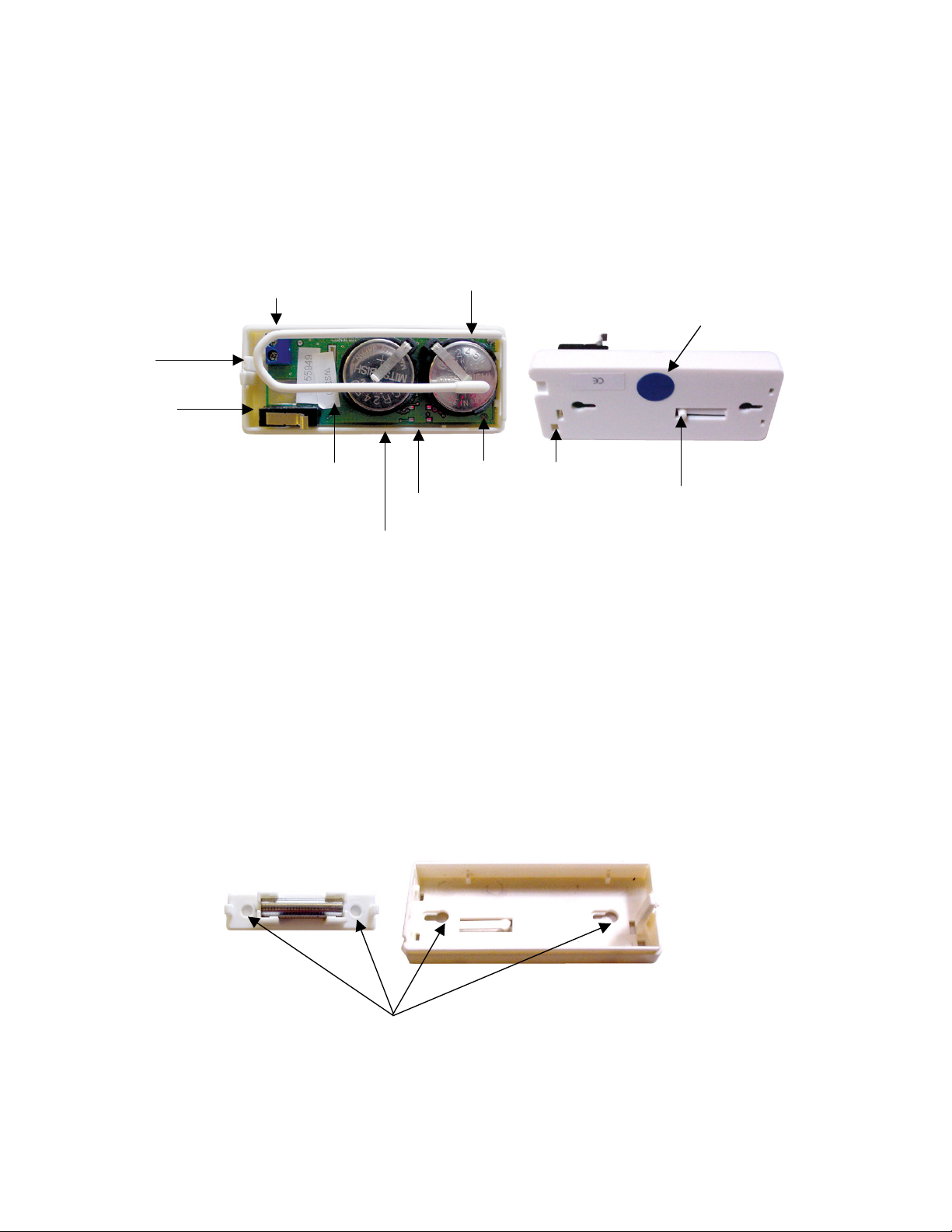
Up to 5 years life span from 2 x CR2450 3V lithium batteries
Utilises Latest Surface Mount Technology.
Microprocessor Controlled.
Tamper Protected Case (Top and bottom)
Sends Alarm, Supervision, Tamper & Low Battery Signals to
compatible Rhino receivers (KISSRX,RXPRO,SMS8RX)
Optional separate code/zone for shock sensor alarm
Individual Codes Sent To Compatible Receiver:
(The red transmission LED indicator will illuminate each time a radio signal is being sent)
Reed Open (Transmitted when magnet is moved away from main unit)
Reed Close (Transmitted when magnet is moved next to main unit)
Note: When the magnet is moved in range of the reed it will transmit a reed OPEN signal followed
immediately by a reed CLOSED signal. This it to maintain compatibility across all receiver products as
some do not recognize the reed “CLOSE” transmission.
Low Battery (Transmitted when battery voltage reaches 4.5V)
Supervision (Transmitted once at least every 2.25 to 3 hours)
Tamper (Transmitted when either the top case of the main unit is removed, or the main unit is removed
from the wall)
Note: A tamper OPEN signal will be sent when the tamper is open and when the tamper is closed it will
send tamper OPEN followed immediately by tamper CLOSE. This it to maintain compatibility across all
receiver products as some do not recognize the tamper “CLOSE” transmission. Both tampers are
connected in series i.e. for a “tamper close” to be sent, both tampers must be sealed but only one tamper
has to be opened to send “tamper open”.
Shock Resonance (Impact) Sensor
Inside the unit there is a special circular brass shock sensing “piezo” plate.
NOTE: Do Not Touch The Piezo Plate Or Drop The Unit As You May Cause Circuit Damage.
This device is able to sense vibrations that the unit is attached to. This may be a door, window, counter
display etc. When an impact is sensed that is greater to or equal to the current programmed level the unit
will transmit the alarm signal. The red transmission indicator LED light inside the unit will turn on to
indicate when the unit is transmitting.
SENSITIVITY LEVEL ADJUSTMENT:
Follow the steps below to set your desired shock sensor sensitivity level.
Please Note: Your WSRI will remember the stored shock sensor sensitivity level even if power is removed.
1. With the case cover removed, press the learn button (small push button next to the batteries).
2.
Within 12 seconds, physically strike the object that the shock sensor is protecting. This impact should
be of an appropriate level of force for which you would want your alarm system activated i.e. for a front
door you would not want someone merely knocking firmly on your door to activate your alarm.
However, it they bashed or kicked the door you would want the alarm activated. If you set the system
to a highly sensitive level, then you may experience false alarms.
3.
You can test the stored sensitivity level by making sure the indicator light turns on when you hit the
protected object with equal to or greater force to that of the saved level.
OPERATION INSTRUCTIONS FOR

NOTE: If the shock level is that is learnt is too small or too large, the unit will set itself to a default sensitivity
level (75% of the maximum possible sensitivity). For each installation the unit must be properly tested to reduce
any chance of a false alarms as every door & window will react slightly differently to vibration on impact.
TO MAKE THE SHOCK SENSOR TRANSMIT ON A SEPARATE ALARM CODE:
In normal default operation, your WSRI will transmit the same code as “Reed Open” when the shock sensor is activated.
This would mean you are using your receiver to activate the one zone on your alarm system in the event of either the reed
switch or shock sensor being activated.
If however you wish to have the reed switch and shock sensor to activate separate zones on your alarm system, you will
not be able to use the supervision function unless you are using the Pima-PRO Alarm Panel & PIMARX Serial Receiver
which allows you to turn off supervision on any chosen zone. This is because the supervison / low battery / and tamper
signals can only be communicated on the primary (reed switch) channel.
If you would like to have the reed switch and shock sensor activate two separate zones, carry out the following procedure:
1. Remove power by removing one of the batteries.
2. Wait at least 10 seconds.
3. Now, whilst holding down the program button, replace the battery you removed.
4. Keep holding down the program button for 5 seconds once the battery is inserted.
5. Your WSRI will now transmit different alarm codes for the reed switch and shock sensor.
Note: You can revert back to both the reed switch and shock sensor utilising the same identical code by repeating the
above procedure.
When the WSRI is set to transmit in 2 channel mode, when programming your receiver treat your WSRI as two separate
wiereless alarm devices i.e. you will setup up two zones on your alarm system, and then learn in the alarm code for reed
open into one of your zones, and then separately learn in the code to the other zone for the shock sensor.
Using As A Universal Transmitter:
The universal transmitter terminals are connected in series with the reed switch. To “seal” this zone the
universal transmitter terminals must be shorted and the magnet must be next to the main unit.
If only the universal transmitter terminals are required to operate, simply fix the magnet next to the WSR. Now
the transmitter will send “open” when the terminals change state from short to open and will send “close” when
the the terminals change state from open to short.
If you wish to use both reed and universal transmitter terminals then the connections to the terminals should
be normally closed as on alarm conditions when either the reed or the terminal become open the “open” signal
will be sent and “close” when they are both sealed again.
Note: The universal transmitter connections must not have anything other than a switched contact connected
to it i.e. nothing that supplies power or draws current. Common connections would be to the alarm output
wires from a hardwired sensor (to make it wireless) or any reed / push button switch / other alarm sensor etc

Installation:
IMPORTANT!
The universal transmitter will not work if a magnet is not next to the reed switch and the reed switch
will not work if the universal transmitter terminals are open (not connected).
When using the shock sensor with a RC-PRO before you learn in the transmitter you must follow the
procedure above to make the roller shutter transmit on a separate channel. If you have already attempted to
learn it in you must delete and relearn it in once they are on separate channels. This will prevent automatic
restorals from cause incorrect operation.
To open the case there is a notch in the end of both the reed and magnet cases that is simply pushed using a
small flat head screwdriver to open.
With the main unit, bend the “release tab” away from the board to allow the printed circuit board to be
removed and gain access to the mounting screw holes.
Note: The glass tube containing the reed switch is particularly fragile, so take extreme care when removing
the PCB. Do not drop or allow other items to come in contact with the electronics.
Using the screws provided, attach the cases to the selected door / window frame.
Note: The maximum spacing between the reed and the magnet should not be more than 10mm apart in the
closed position. Replace the electronics and top cases.
Battery Replacement:
Replacement batteries are model CR2450 (3 Volt Lithium).The batteries should be replaced every 3 years or
whenever you receive a low battery signal from your alarm. Both batteries must be replaced at the same time.
Batteries must be inserted positive (+) side up.
Blue dot on bottom of case indicates
which side the reed switch is located
Universal transmitter
termi
nals
Tamper 1
Tamper 2
PCB release TAB
Antenna (DO NOT CHANGE
IT’S POSITION OR SHAPE!)
Transmit LED
Software Version &
Code number
Reed side indicator
Universal
transmitter
wire exit
Mounting screw holes
Program button

Table of contents
Other RHINO Accessories manuals
Popular Accessories manuals by other brands

Elkron
Elkron DC600 Installation, programming and functions manual

Waterpik
Waterpik WP-800 Series instruction manual

Grandview
Grandview CB-MRC instruction manual

Imetec
Imetec F2005 operating instructions

Alula
Alula Home Disaster RE119 quick start guide

IV Produkt
IV Produkt NEW EcoCooler Operation and maintenance