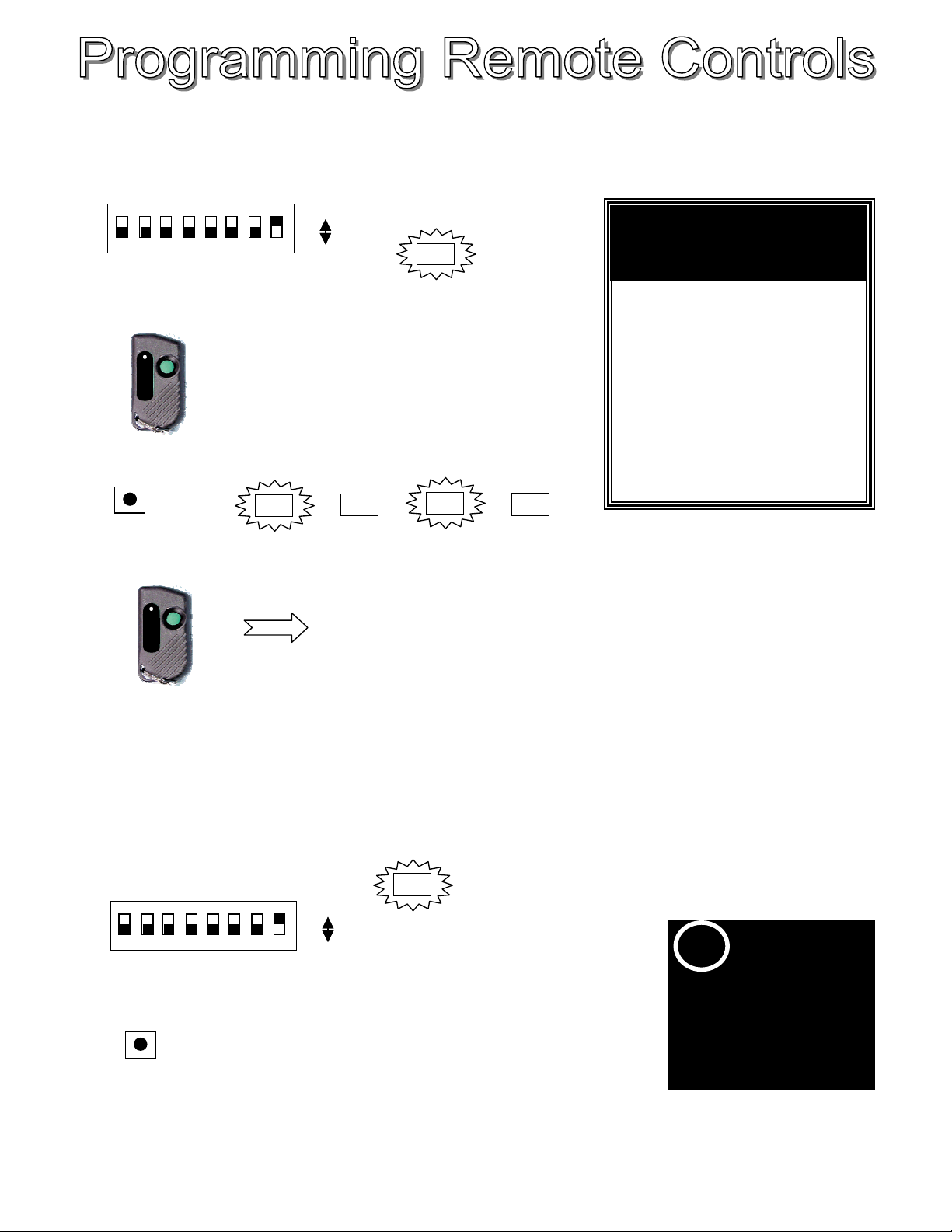
6
TO ADD A REMOTE CONTROL
1. On Bank 1, set dipswitch Number 8 only to ON. The yellow Program LED will come on. (If the LED flashes, check that,
you don't have more than one dipswitch set to on).
2. Press & Hold the button on your remote.
3. Press the Add Button. The red Valid LED will start flashing at 0.5Hz.
4. Now release the button on the remote. The red valid light will turn off.
ACOM
5. Repeat steps 2 - 4 for any extra remotes that you wish to add. Maximum of 5 can be used.
6. Return dip switch 8 to the OFF position. The yellow program light will turn off.
TO DELETE ALL REMOTE CONTROLS
1. On Bank 1, set dipswitch Number 8 to ON. The yellow Program LED will come on. (If the LED flashes, check that, you
don't have more than one dipswitch set to on).
2. Press the Delete Button.
3. All remote controls will now have been erased from the memory of the
receiver.
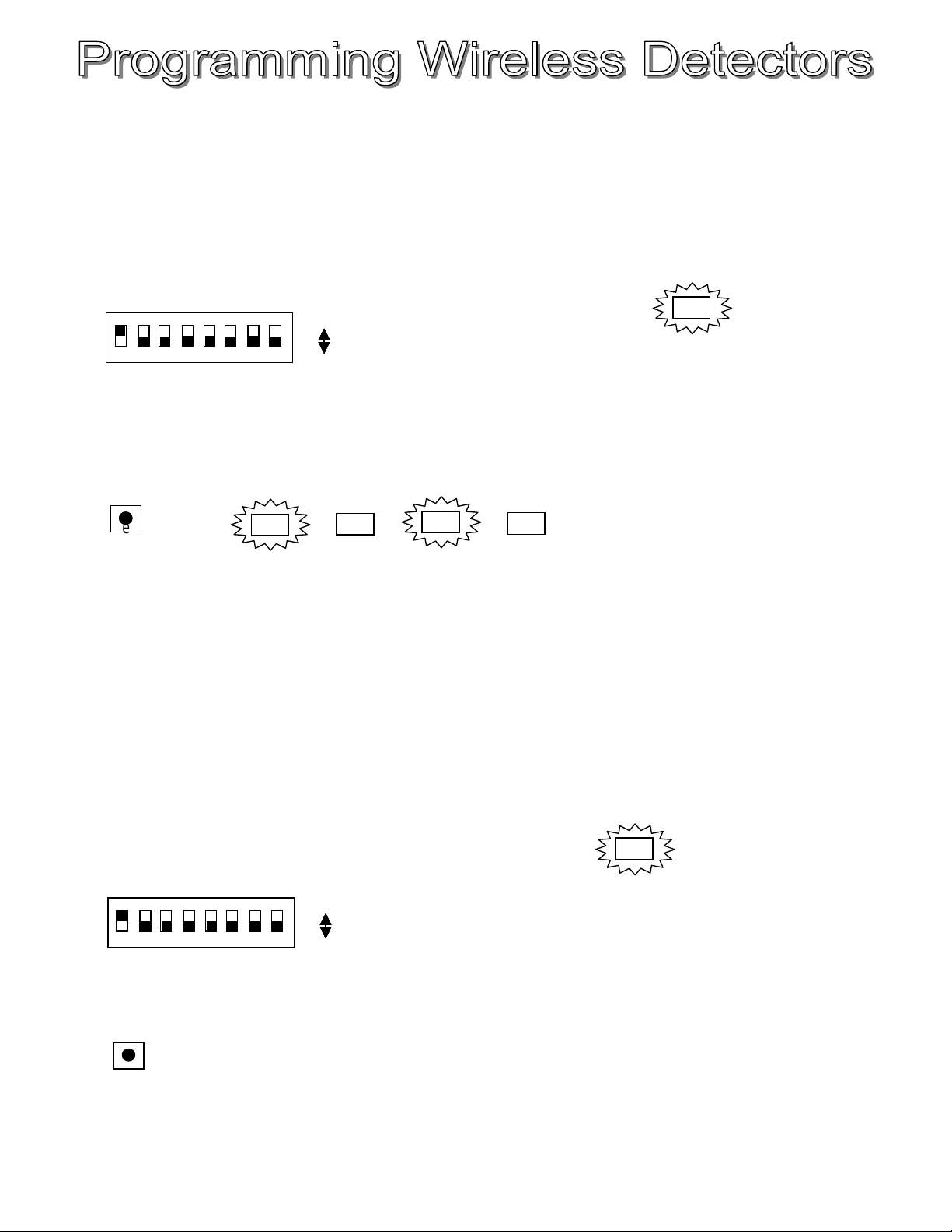
Due to the excellent performance of the
receiver, you are likely to "swamp" the
receiver with too much RF signal if you
transmit within 5 metres of the receiver.
To prevent this from occurring, simply
remove the antenna from your receiver
hilst programming. You will now have
to be within approx 1m of the receiver
whilst programming.
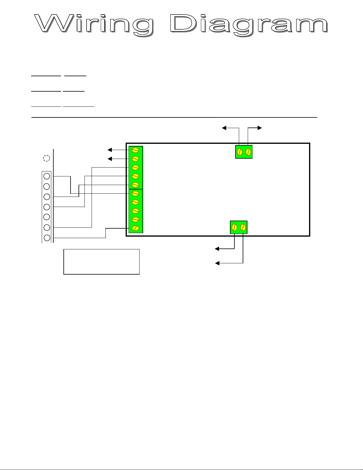
1 2
4
7
Bank 1
ON
OFF
1 2
4
7
Bank 1
ON
OFF
1 2
4
7
Bank 1
ON
OFF
1 2
4
7
Bank 1
ON
OFF
%
Delete
Add %
Add …
%
%
Hold
NOTE WHEN PROGRAMMING
REMOTES OR WIRELESS
DETECTORS
!IMPORTANT
When programming make
sure that no detectors are
transmitting, as they will
interfere with you
programming procedure.