1
1
23
3
4
4
5
13
6
1516171819
20
4
4
21
21
22
23
24
11
78
14
910
12
10
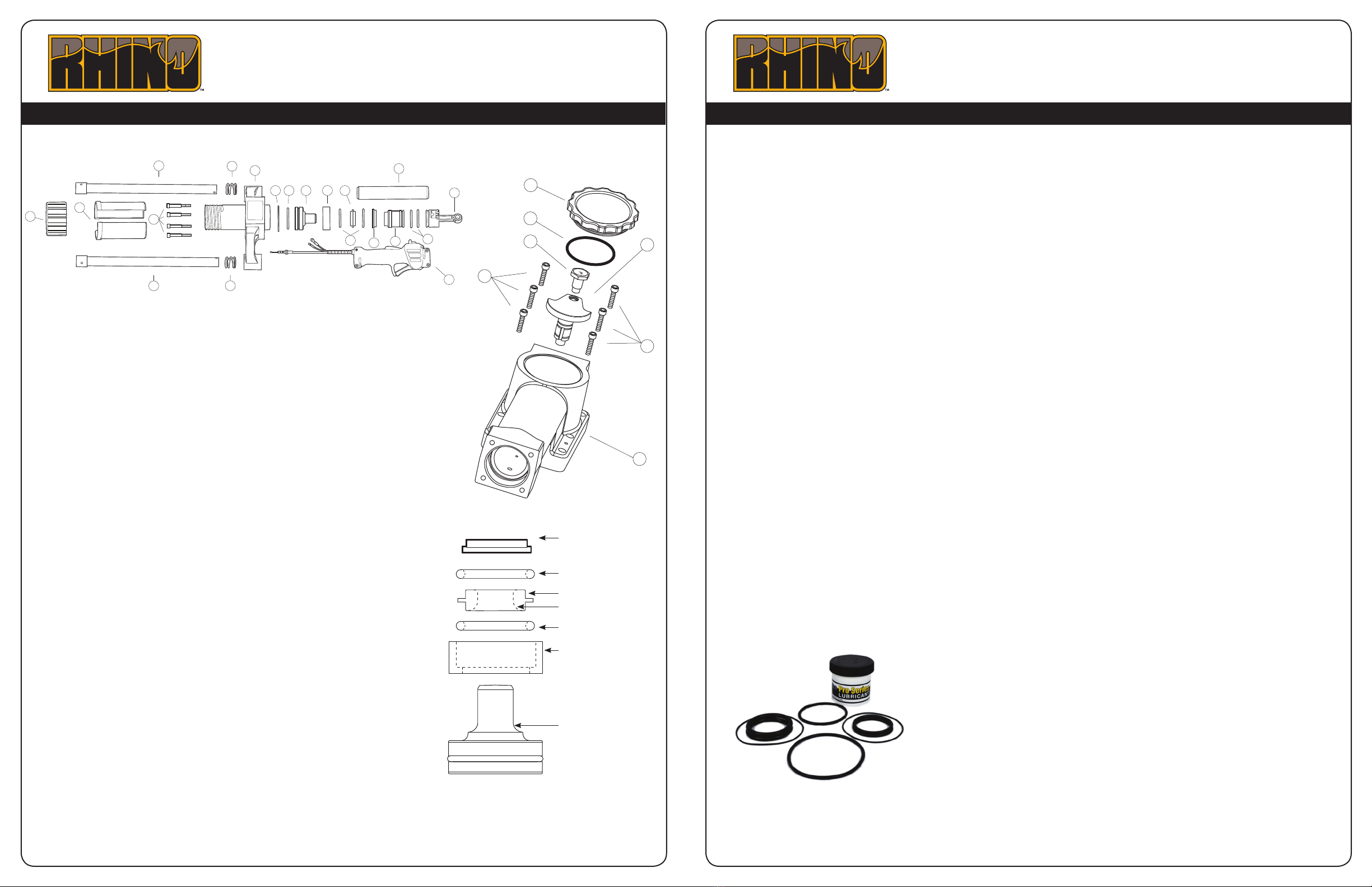
7: Take the components out from the Anvil O-ring Cup (#16)
and inspect all for damage. Replace the used Large Retainer
O-rings (#14) with new ones from the kit. Lube all components.
Conrm that the Large Retainer (#15) is positioned correctly, as
shown, incorrect installation can result in damage to the driver.
Re-install the Anvil O-ring Cup with components into the
chuck tube.
8: Install the Anvil O-ring Retainer (#10) on top of the Anvil
O-ring Cup and its components. The Anvil O-ring Retainer only
installs one way, installing it wrong may result in damage to the
driver. Set aside the Lower Body (#20), all parts attached, and
focus on the Body Assembly (#2)
9: Remove the Crankcase Cover (#25) and discard Crankcase
Cover O-ring (#26). Lube and install the new Crankcase Cover
O-ring from the kit. Set aside.
10: With a black marker, or alike, mark the Piston Assembly
(#7). Re-install it facing in the same direction when assembling
to maintain the original wear pattern. Note that the Crank Pin
(#27) is left hand thread. Use a 7/8 deep-well socket to remove
the Crank Pin. Inspect the Crank Pin and threads for damage
as well as the Crank Shaft (#29) threads. Extract the Piston
Assembly and Hammer (#9) from the Body Assembly (#6) and
remove the O-rings and discard. Inspect the Self Lubricating
Bronze Sleeve Bearing in the Connecting Rod of the Piston
Assembly and check either for wear or out of roundness. Piston
Assembly is only available as a complete assembly. Lube the
Hammer and Piston Assembly O-ring groove and install one of
the Piston/Hammer O-rings (#8) from the kit on each. Set aside.
Insert O-ring into Anvil O-ring Cup, then
insert Large Retainer (with large radius at
bottom towards the anvil), then insert other
O-ring.
25
26
27
28
6
29
28
11: Clean all lubricant from the Crank Pin (#27) and lay on a shop towel along with the four Lower Body
Bolts (#22) and two Handle Bolts (#1). Including the Crankshaft (#29) and Side Handle Assembly’s
(#21) spray all threads with Loctite N 7649 Primer and let dry.
12: Clean out all lubricant from the Body Assembly (#6). Install Piston Assembly (#7) with the connect-
ing rod facing the top of the driver and mark made in Step 10 facing outward. Locate the Self Lubricat-
ing Bronze Sleeve Bearing in the Connecting Rod of the Piston Assembly and align it with the threads
in the Crank Shaft (#29). Apply Loctite 243 Threadlocker to the Crank Pin Threads and install it through
the connecting rod of the piston assembly. Crank Pin has left hand threads. Torque to 360 in/lbs. Install
Hammer (#9) with the Hammer O-ring (#8) towards the top of the driver.
13: Obtain the Lower Body Assembly from Step 7. Place the Chuck Tube O-ring (#19) on top. Apply
Loctite 243 Threadlocker to the four Lower Body Bolts (#22). Install the Throttle (#12) on the Side Han-
dle Assembly (#21). Install the Lower Body Assembly on the Body Assembly (#6) and torque to 251 in/
lbs. Place the top of both side handle assemblies (#21) through the top handle bracket (#2) and slide
the throttle to its lowest point and tighten the upper 5/32” HEX bolt used to hold the Handles in their
most up position. Make sure the handle springs (#4) are installed in the top handle bracket.
14: Install the handle collars (#3) with the mark made in Step 4 in the up position. Insert both
handle bolts (#1) into the Top Handle Assembly (#2) so that the threads are exposed. Apply Loctite 243
Threadlocker to the bolt threads and install the Top Handle Assembly on to the Handle Collars. Apply
downward force to compress the Handle Springs (#4) and torque the Handle Bolts to 132in/lbs.
15: Hand tighten the Chuck-Lok Locking Nut (#24) onto the Master Chuck (#20). Fill the crankcase with
one tub of lubricant from the kit. With a 7/8” Deep-well Socket spin the Crank Pin (#27) counter-clock-
wise feeling for any binding on the Piston Assembly (#7). Locate Crankcase Cover (#25) with Crank-
case Cover O-ring (#26) from Step 7 and install. Hand tighten only.
Rhino®Fence Pro™Service Kit Installation Rhino®Fence Pro™Service Kit Installation
(#14) O-ring
(#14) O-ring
(#16) Anvil O-ring Cup
(#17) Anvil with O-ring
(#15) Large Retainer
Large Radius
(#10) Anvil
O-ring Retainer
For more information on installing the Fence Pro Service Kit, visit www.rhinotool.com.
7
98
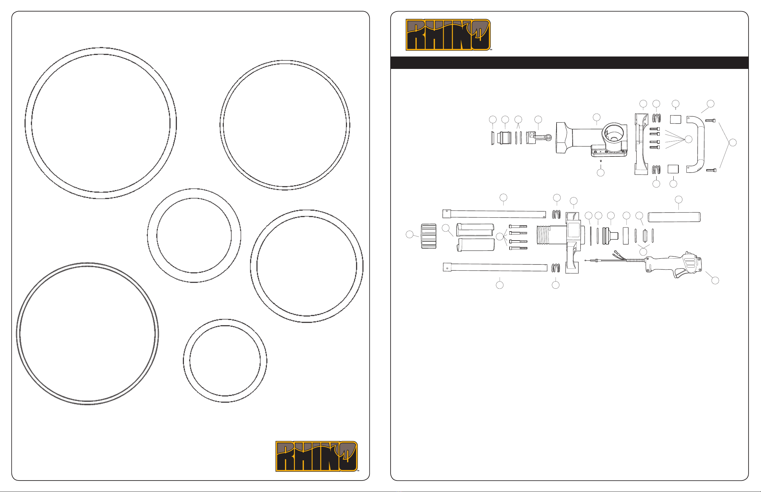
Fence Pro Service Kit Part No. 301508:
(# location indicated on exploded parts diagram)
(#8) O-Ring Seal for Piston and Hammer (2) P/N: 301610
(#26) O-Ring Seal for Pro-Series Crankcase Cover P/N: 301617
(#14) Large Retainer O-Ring Seal (2) P/N: 301614
(#18) Anvil O-Ring Seal P/N: 301616
(#19) Chuck Tube or Sleeve O-Ring Seal P/N: 301618
Rhino Pro-Series Lubricant (2)