Rhotheta RT-1000 C User manual

RHOTHETA Elektronik GmbH User Manual RT-1000 C [Rev 4.02.d]
User Manual
VHF Direction Finder System
RHOTHETA RT-1000 C

RHOTHETA Elektronik GmbH User Manual RT-1000 C [Rev 4.02.d]
Edited by:
RHOTHETA Elektronik GmbH
Kemmelpark
Dr.-Ingeborg-Haeckel-Str. 2
82418 Murnau
Germany
Tel.: +49 8841 4879 - 0
Fax: +49 8841 4879 - 15
Internet: www.rhotheta.de
E-Mail: email@rhotheta.de
Copyright © RHOTHETA Elektronik GmbH
All rights reserved
- Issue: 2017/05/17 [Rev 4.02.d]
- Document-ID: 12-9-1-0004-3-1-2
NOTE
The manufacturer reserve the right to make modifications at any time and without previous information
of the here described product.

RHOTHETA Elektronik GmbH User Manual RT-1000 C [Rev 4.02.d]
Section 1
General Information
General Description, Characteristics, Flexible System Configuration,
Bearing Display and Bearing Quality Analysis, Antenna System,
Antenna Mast, Technical Data
Section 2
Controller
RTC 1100.A
Section 3
Receiver Unit
RTR 1200.A
Section 4
Direction Finder Antenna
RTA 1300.A
Section 5
Appendix
Approval of the Direction Finder System and Manufacturer Declarations
Inter-wiring of the Direction Finder
Test Record

RHOTHETA Elektronik GmbH User Manual RT-1000 C [Rev 4.02.d]
- 1.1 -
1 GENERAL INFORMATION
List of Contents:
1GENERAL INFORMATION ............................................................ 1.1
1.1 General Description ...................................................................................... 1.2
1.1.1 Options ...............................................................................................................................1.2
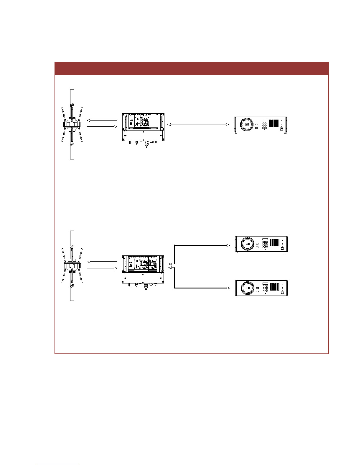
1.1.2 System Configuration .......................................................................................................1.3
1.1.3 Subsystems .......................................................................................................................1.4
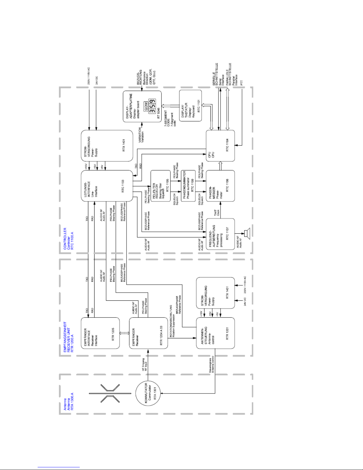
1.1.4 Block Diagram ...................................................................................................................1.5
1.2 Technical Data ............................................................................................... 1.6
1.2.1 Basic Data ..........................................................................................................................1.6
1.2.2 Electrical Characteristic ....................................................................................................1.7
1.2.2.1 System Characteristic ................................................................................................1.7
1.2.2.2 Power Supply ..............................................................................................................1.8
1.2.2.3 Interface ......................................................................................................................1.8
1.2.3 Mechanical characteristics ...............................................................................................1.9
1.2.3.1 Antenna RTA 1300.A ..................................................................................................1.9
1.2.3.2 Controller RTC 1100.A .............................................................................................1.10
1.2.3.3 Receiver Unit RTR 1200.A .......................................................................................1.11
1.2.4 Environmental Conditions ..............................................................................................1.12
1.2.4.1 Antenna RTA 1300.A ................................................................................................1.12
1.2.4.2 Controller RTC 1000.A .............................................................................................1.12
1.2.4.3 Empfangseinheit RTR 1200.A .................................................................................1.12
1.3 Safety ............................................................................................................ 1.13
1.3.1 Symbols ............................................................................................................................1.13
1.3.2 Basic Safety Notes ..........................................................................................................1.14
1.4 Disposal within the European Union ......................................................... 1.14
1.5 Disposal outside the European Union ....................................................... 1.14

RHOTHETA Elektronik GmbH User Manual RT-1000 C [Rev 4.02.d]
- 1.2 -
1.1 General Description
The direction finder system RT-1000 C is designed for ATC (air traffic control) and VTS (vessel traffic
service) application. The system can be used in stationary and mobile applications.
1.1.1 Options
Options
Option Designation
Information
Part No.
Antenna Model RTM-1501 Accessories:
System Test and Maintenance
RTM-1501 A
Service-Kit RT-1000 Accessories:
System Test and Maintenance
RTM-1500 A
Antenna Mast RTA 1306.A Accessories: Antenna mounting RTA-1306 A
Cabinet RTA 1306.700 Accessories:
Antenna mounting
RTA-1306.700 A
RTA-1306.700 B
RTA-1306.700 D
Mounting for cabinet RTA 1311.A Accessories: Cabinet mounting RTA-1311 A
Obstacle Light Accessories: Antenna mounting RTA-1306.740 A
RTA-1306.740 A-001
Improved Bearing Accuracy 1° RMS1) Antenna Calibration RT-9021
VHF maritime band with VHF air band 2) Unlock: 156,000-174,000 MHz -
VHF maritime band with Emergency Fre-
quency 121,5 MHz
3)
Unlock: 156,000-174,000 MHz
+ 121, 500MHz
-
Second DF Channel RTR 1245
Modification:
Equipped with a second receiver
module and an additional Controller
RTR 1245 A
RTR-1245g A
Red Display
Modification:
Indication of frequency and bearing
in red colour.
RTU-1000 A
RTU-1000 C
8,33 kHz Channel Spacing for air band
Unlock:
Support of the 8,33 kHz channel
spacing
-
AIS Suppression Notch Accessories: VTS RT-8730
RS232 to LAN Converter Accessories:
Network Connectivity
RT-8757
1) The "Improved Bearing Accuracy" option is achieved by calibration of the antennas.
2) Frequency Range Extension to maritime band 156,000 – 174,000 MHz
3) VHF maritime band 156,000 – 174,000 MHz incl. Emergency Frequency 121,500 MHz instead of
VHF air band 118,000 – 174,000 MHz

RHOTHETA Elektronik GmbH User Manual RT-1000 C [Rev 4.02.d]
- 1.3 -
1.1.2 System Configuration
System Configuration RT-1000
6-wi re t elephon c able
C o n t r o l l e rR e c e i v e r U n i t
max . 10 km
D F A n t e n n a
RF-Kabel
control l
Antenna
RTA 1300.A RTR 1200.A RTC 1100.A
Standard Configuration:
The system operates in „remote mode“. The direction finding antenna is installed remotely from the controller,
at a location favourable for direction finding. Receiver, demodulator and antenna control module are integrat-
ed in the receiver unit located at the antenna position. They are connected to the controller by means of a 6-
wire line.
C o n t r o l l e rR e c e i v e r U n i t
D F A n t e n n a
RF-Kabel
cont rol l
Anten na
RTA 1300.A RTR 1200. A RTC 1100. A
6 wir e tel epho ne cabl
ma x. 10 k m
6 wir e tel epho ne cabl e
ma x. 10 k m
C o n t r o l l e r
RTC 1100. A
Configuration for 2 simultaneous channel operation:
The DF system is equipped with a second receiver module and an additional Controller. This offers 2 inde-
pendent operator sides.

RHOTHETA Elektronik GmbH User Manual RT-1000 C [Rev 4.02.d]
- 1.4 -
1.1.3 Subsystems
Subsystems
No
Designation
File Reference
Part No.
1
RT-1000 Controller RTC 1100.A
12-9-2-0017-2-1
RTC-1100 A
2
RT-1000 Receiver Unit RTR 1200.A
12-9-2-0018-2-1
RTR-1200 A
3
RT-1000 Antenna RTA 1300.A
12-9-2-0019-2-1
RTA-1300 A

RHOTHETA Elektronik GmbH User Manual RT-1000 C [Rev 4.02.d]
- 1.5 -
1.1.4 Block Diagram

RHOTHETA Elektronik GmbH User Manual RT-1000 C [Rev 4.02.d]
- 1.6 -
1.2 Technical Data
1.2.1 Basic Data
Basic Data
Parameter
Condition
Data
DF method
-
Doppler (3 kHz rotation frequency)
Response time
1)
With sufficient signal strength
≤ 500 ms typ. ≤ 400 ms
Minimum signal duration2)
-
typ. ≤ 300 ms
Internal system resolution
-
0,5°
Frequency range3)
Air band VHF
118,000 – 136,975 MHz
Maritime band 156,000 – 174,000 MHz
Operating Channels
Air band VHF 760 (25 kHz)
2278 (8,33 kHz)
Maritime band Channel 01 -
88 (incl. duplex
channels)
Channel Spacing Air band VHF 25 kHz
8,33 kHz (Option)
Maritime band
25 kHz
Bearable modulation types
-
A3E, F3E, A3X (ELT-modulation)
Number of bearing Channels simultaneous bearing Chan-
nels
1 (Optional 2)
Polarization
-
vertical
Polarization Error With field vector rotation up to
45°
±1°
Cone of confusion
Bearing Fluctuation ±5°
≤ 45° / typ. 35°
Height of installation site
Max. 3000 m a.s.l.
MTBF Complete System ≥ 168.000 h
1) Time required determining and displaying a bearing value
2) Minimum required signal duration to determine a bearing value
3) Frequency range depending on the software configuration (Unlock Options)

RHOTHETA Elektronik GmbH User Manual RT-1000 C [Rev 4.02.d]
- 1.7 -
1.2.2 Electrical Characteristic
1.2.2.1 System Characteristic
System Properties
Parameter Condition Limit Typical
Bearing sensitivity
118,000 – 136,975 MHz,
±2°bearing fluctuation ≤ 5 µV/m ≤ 2,5 µV/m
≤ 4 µV/m
3)
156,000 – 174,000 MHz,
±2° bearing fluctuation ≤ 5 µV/m
≤ 2,5 µV/m
≤ 4 µV/m
3)
Bearing accuracy1)
118,000 – 136,975 MHz 2° RMS
1° RMS (Opt.)
2)
2° RMS
1° RMS (Opt.)
2)
156,000 – 174,000 MHz 2° RMS
1° RMS (Opt.)
2)
2° RMS
1° RMS (Opt.)
2)
1) Measured in undisturbed wave field, with un-modulated signal, with sufficient signal strength
2) Option with improved Bearing Accuracy 1° RMS
3) Bearing sensitivity for configuration with 2 DF channels

RHOTHETA Elektronik GmbH User Manual RT-1000 C [Rev 4.02.d]
- 1.8 -
1.2.2.2 Power Supply
Technical Data
Parameter
Condition
Data
Power supply
AC
115 / 230 V ±15 %; 47...63 Hz
DC
24 V -10 % / +20 %
Power consumption
Controller
15 VA
Receiver Unit
15 VA (65 VA with heater (300
VA peak))
1.2.2.3 Interface
Interfaces and Protocols
Designation
Connector
Transmission Type
Protocol
Max. Data Rate
Serial Interface 1x D-Sub
9-pol Female
RS-232 ASCII-8-bit 1200 baud

RHOTHETA Elektronik GmbH User Manual RT-1000 C [Rev 4.02.d]
- 1.9 -
1.2.3 Mechanical characteristics
1.2.3.1 Antenna RTA 1300.A
Antenna RTA 1300.A with Antenna Mast RTA 1306.A
400
1120
3120
141
C l a m p i n g A e r i a
42
4100
5700
200
ø40
+1
- 0
1490
Mechanical Characteristis
Subsystem
Width
Height
Weight
RT-1000 Antenna RTA 1300.A
400 mm
3120 mm
10,2 kg
RT-1000 Antenna RTA 1300.A + Antenna Mast RTA 1306.A
1420 mm
5700 mm
120 kg
Antenna can be folded down for maintenance
DF antenna RTA 1300 with lightning rod and mast tube
Antenna Mast RTA 1306.A
All dimensions are in [mm]
antenna rotator for accuracy test

RHOTHETA Elektronik GmbH User Manual RT-1000 C [Rev 4.02.d]
- 1.10 -
1.2.3.2 Controller RTC 1100.A
Controller RTC 1100.A
Mechanical Characteristis
Subsystem
Length
Width
Height
Weight
RT-1000 Controller RTC 1100.A
482,6 mm
377,7 mm
132,5 mm
7,4 kg
1
1 The weight is valid for the Controller with remote operation mode.

RHOTHETA Elektronik GmbH User Manual RT-1000 C [Rev 4.02.d]
- 1.11 -
1.2.3.3 Receiver Unit RTR 1200.A
Receiver Unit RTR 1200.A
332
355
236.7
340
11
79.1
271
120
210
146.7
Ø5 , 5 0
Mechanical Characteristis
Subsystem
Length
Width
Height
Weight
RT-1000 Receiver Unit RTR 1200.A 355,0 mm 236,7 mm 271 mm 6,5 kg 2
7,6 kg
3
2 valid for single channel unit with 1 receiver
3 Valid for dual channel unit with 2 receivers

RHOTHETA Elektronik GmbH User Manual RT-1000 C [Rev 4.02.d]
- 1.12 -
1.2.4 Environmental Conditions
1.2.4.1 Antenna RTA 1300.A
Environmental Conditions
Parameter
Data
Wind load
(with constant wind speed)
150 km/h / 135 N
180 km/h / 195 N
allowed wind speed
≤ 240 km/h
Operating temperature range
-40°C…+80°C
Storage temperature range
-40°C…+80°C
Ingress protection
IP 65
1.2.4.2 Controller RTC 1000.A
Environmental Conditions
Parameter
Data
Operating temperature range
-20°C…+55°C
Storage temperature range
-40°C…+60°C
Humidity 95% at 35°C
60% at > 35°C
1.2.4.3 Receiver Unit RTR 1200.A
Environmental Conditions
Parameter
Daten
Operating temperature range
-40°C…+60°C
Storage temperature range
-40°C…+60°C
Humidity 95% at 35°C
60% at > 35°C
Ingress protection
IP 65

RHOTHETA Elektronik GmbH User Manual RT-1000 C [Rev 4.02.d]
- 1.13 -
1.3 Safety
RHOTHETA Elektronik GmbH is constantly striving to keep the safety standard of its products up to
date. We try to offer our customers the highest possible degree of safety.
RHOTHETA products are designed and tested in accordance with the current applicable safety regula-
tions. The compliance with these standards is continuously monitored by our quality assurance system.
This product is built in according to the EU certificate of conformity, and has left the factory in perfect
technical condition.
To maintain this safety condition and to ensure safe operation, the user must observe all instructions
and warnings which are provided. For all questions regarding these safety instructions, RHOTHETA
Elektronik GmbH will be at your disposal at any time.
Observing the safety instructions will help to prevent personal injury or damage from hazards of all
kinds. This requires that the following safety instructions have to be read and understood before using
the product, and they have to be observed while using the product. All further safety instructions, such
as personal safety instructions, which appear in the relevant parts of the product documentation, also
must be strictly observed.
Moreover, it is the responsibility of the user to use the product in a proper way. It is not allowed to use
the DF system RT-1000 C in a way which can cause damage to a person or a thing.
The use of this product for other than its designated purpose or in disregard of the manufacturer's in-
structions is in the responsibility of the user. The manufacturer assumes no responsibility for the
misuse of the product.
The manufacturer is not liable beyond the scope of legal rules!
This manual is part of the product RT-1000 C and is to keep during the lifetime and pass on to the
product.
1.3.1 Symbols
NOTE
With “Note”, tips or supplementary notes are marked which must be observed and make work easier.
ATTENTION
means that failure to observe the instructions can result in property damage
or loss of data.
WARNING
means that failure to observe the instructions may be a danger to health or
life.

RHOTHETA Elektronik GmbH User Manual RT-1000 C [Rev 4.02.d]
- 1.14 -
1.3.2 Basic Safety Notes
• At all activities, local or national safety and accident prevention regulations must be observed.
• Only use manufacturer prescribed components and / or use only material recommended by the
manufacturer and do not modify them.
• Only connect approved accessories or ancillary equipment.
• The product may only be opened by authorized service personnel.
• The product voids its type approval on operating with unauthorized modifications on the device
or unintended use.
1.4 Disposal within the European Union
Product Recycling
Product labelling in accordance with EN 50419
At the end of product life, this product may not to be disposed together with normal household waste.
Even disposal via the municipal waste disposal collection for electrical and electronic equipment is not
permitted.
The correct disposal of this product helps to protect the environment and prevent any potential damage
to the environment and human health, which can occur due to improper handling of the product.
• Therefore, supply the device to an electronics recycling after the final taken out of service.
Otherwise
• RHOTHETA Elektronik GmbH takes back all products that are subject to the requirements of
the WEEE Directive (2012/19/EU) of the European Union to supply these products to profes-
sional disposal.
1.5 Disposal outside the European Union
For proper disposal of used electronic equipment in accordance with the respective national regula-
tions in countries outside the European Union please check it with your dealer or the local authorities.
ATTENTION
Read and observe the following instructions, warnings and safety instruc-
tions of the manufacturer!

RHOTHETA Elektronik GmbH User Manual RT-1000 C [Rev 4.02.d]
- 2.1 -
2 CONTROLLER RTC 1100.A
List of Contents:
2CONTROLLER RTC 1100.A .......................................................... 2.1
2.1 Key to Front and Rear Views ........................................................................ 2.5
2.2 Preparation for Use ....................................................................................... 2.9
2.2.1 Grounding ..........................................................................................................................2.9
2.2.2 Mains Voltage ....................................................................................................................2.9
2.2.3 Mains Fuse .......................................................................................................................2.10
2.2.4 DC Voltage Connection...................................................................................................2.10
2.2.5 Power Supply ...................................................................................................................2.11
2.2.6 Connection of the Receiver Unit ....................................................................................2.11
2.2.7 Rack Mounting .................................................................................................................2.12
2.2.8 Switching on / Reaction from Unit .................................................................................2.12
2.2.9 Phase Adjustment ...........................................................................................................2.12
2.2.9.1 Adjustment Using RTM 1501 Dummy Antenna (Option) ......................................2.13
2.2.9.2 Adjustment Using a Transmitter .............................................................................2.13
2.2.10 North Adjustment ............................................................................................................2.14
2.2.11 Adjustment of the Squelch threshold............................................................................2.14
2.2.12 Variation Adjustment ......................................................................................................2.15
2.2.13 Disable Selection of Reference Direction .....................................................................2.16
2.2.14 Ground Transmitter Suppression ..................................................................................2.17
2.3 Display and Operating Functions............................................................... 2.19
2.3.1 Bearing Display and Bearing Quality Analysis .............................................................2.19
2.3.2 Test Function ...................................................................................................................2.19
2.3.3 “REPEAT” Repetition of Bearing Indication .................................................................2.20
2.3.4 Frequency Selection .......................................................................................................2.21
2.3.4.1 Direct Frequency Selection in the 25 kHz channel spacing .................................2.21
2.3.4.2 Direct Frequency Selection in the 8.33 / 25 kHz channel spacing .......................2.22
2.3.4.3 Recalling a Frequency Memory ..............................................................................2.25
2.3.4.4 Programming the Frequency Memory ...................................................................2.25
2.3.5 Direct Selection of Channel Number in Maritime Radio Communication ..................2.26
2.3.6 Scanning ..........................................................................................................................2.27
2.3.6.1 Selection of Scan Mode ...........................................................................................2.27

RHOTHETA Elektronik GmbH User Manual RT-1000 C [Rev 4.02.d]
- 2.2 -
2.3.6.2 Stopping Scanning...................................................................................................2.28
2.3.7 Direct Recall of the Distress Frequency 121.500 MHz .................................................2.28
2.3.8 North Adjustment ............................................................................................................2.28
2.3.9 Selection of the reference directions QDM, QDR, QUJ und QTE ...............................2.29
2.3.10 Checking the Variation adjustment ...............................................................................2.31
2.3.11 Frequency Deviation .......................................................................................................2.31
2.3.12 Error Indication ................................................................................................................2.31
2.3.13 Dimmer (1) "DIM" .............................................................................................................2.32
2.3.14 Volume Control (9) ..........................................................................................................2.32
2.3.15 Headphones Connection (10) .........................................................................................2.32
2.3.16 "STANDBY" Indicator (11) ..............................................................................................2.32
2.3.17 ON / OFF Switch (12) .......................................................................................................2.32
2.3.18 "Line" Mains Switch (19) ................................................................................................2.33
2.3.19 Power Supply "OK" Indicator (21) .................................................................................2.33
2.3.20 "Data-Port" Data Interface (22) .......................................................................................2.33
2.3.21 "Sync" Synchronisation Indicators (23, 24) ..................................................................2.35
2.3.22 "DF Signal 2" Test Plug (26) ...........................................................................................2.35
2.3.23 "R/L" Test Connector (25) ..............................................................................................2.35
2.3.24 "Serial Port" Serial Interface (30) ...................................................................................2.36
2.3.24.1Data Output ...............................................................................................................2.37
2.3.24.2 Data Input ..................................................................................................................2.39
2.3.24.3 "Ser. Port" Plug Wiring (30) .....................................................................................2.42
2.3.24.4 Connection to a Data Terminal or Data Transmission Device .............................2.43
2.3.24.5 Compatibility mode ..................................................................................................2.44
2.3.25 "Parallel Port" Parallel Interface (31) .............................................................................2.44
2.3.25.1 Timing Sequence......................................................................................................2.45
2.4 Installation Dimensions .............................................................................. 2.46

RHOTHETA Elektronik GmbH User Manual RT-1000 C [Rev 4.02.d]
- 2.3 -
List of Figures:
Figure 2-1 Front view .......................................................................................................................... 2.7
Figure 2-2 Rear view ........................................................................................................................... 2.8
Figure 2-3 Mains voltage selector ...................................................................................................... 2.9
Figure 2-4 Mains power connection, mains fuse holder ................................................................ 2.10
Figure 2-5 Variations Adjustment ................................................................................................... 2.15
Figure 2-6 Disabling Selection of Reference Direction ................................................................. 2.16
Figure 2-7 Wiring diagram for ground transmitter suppression .................................................. 2.17
Figure 2-8 Wiring diagram for ground transmitter suppression with non-floating contact ..... 2.17
Figure 2- 9 D-sub-jack 9-way ........................................................................................................... 2.17
Figure 2-10 Bearing Display ............................................................................................................ 2.19
Table of contents
Other Rhotheta Camera Accessories manuals