Rhotheta RT-800 Manual

Installation and Configuration Manual
R
RT
T-
-8
80
00
0
Wideband Precision Direction Finder
RHOTHETA Elektronik GmbH

RHOTHETA Installation and Configuration Manual RT-800
Page 2 of 32
Edited by:
RHOTHETA Elektronik GmbH
Kemmelpark
Dr.-Ingeborg-Haeckel-Str. 2
82418 Murnau
Germany
Tel.: +49 8841 4879 - 0
Fax: +49 8841 4879 - 15
Internet: www.rhotheta.de
E-Mail: email@rhotheta.de
Copyright © RHOTHETA Elektronik GmbH
All rights reserved
-Issue: 2017/11/7 [Rev 1.05.b]
-Display Control Unit: Software ≥[Rev 2.00]
-Document-ID: 12-9-1-0003-3-4-61
Note
The manufacturer reserve the right to make modifications at any time and without previous
information of the here described product.

RHOTHETA Installation and Configuration Manual RT-800
Page 3 of 32

RHOTHETA Installation and Configuration Manual RT-800
Page 4 of 32
Content
1Antenna Installation Considerations ............................................................................. 6
1.1 General Information ................................................................................................................................6
1.2 Installation Recommendation .................................................................................................................7
1.3 Line of Sight and Fresnel Zone ..............................................................................................................8
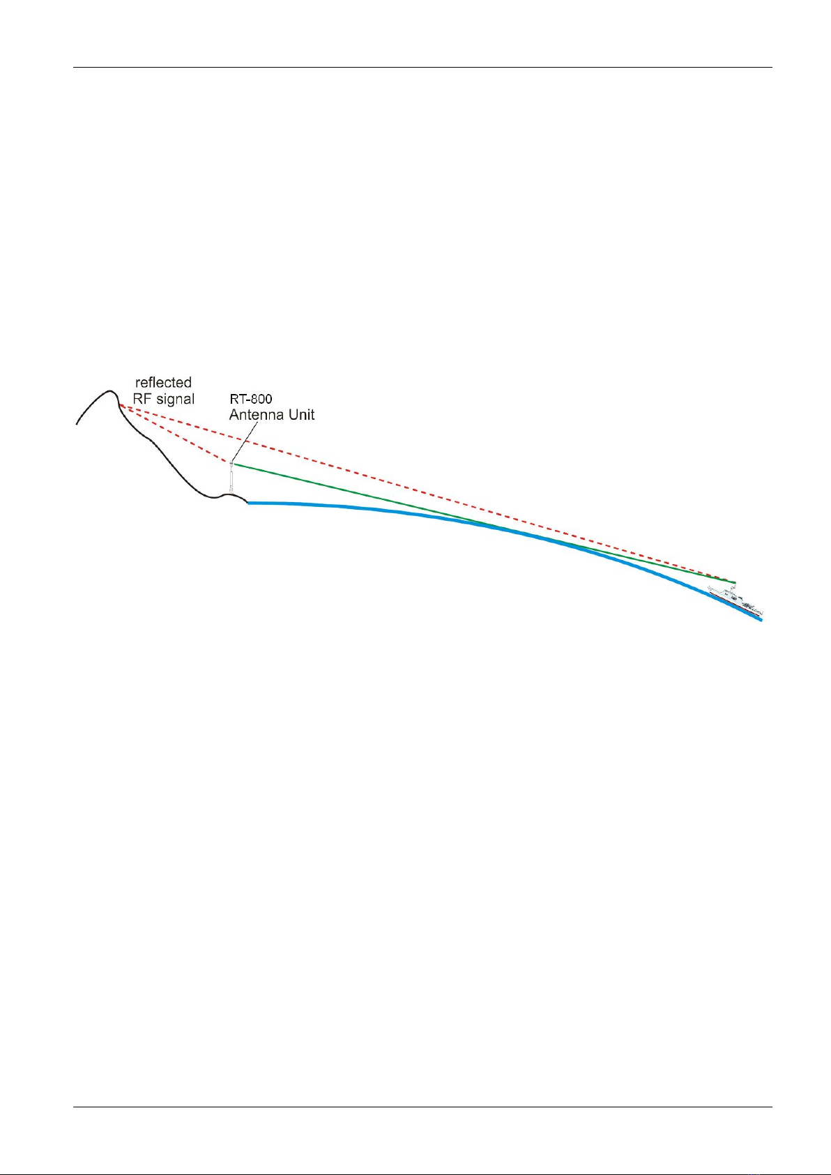
1.4 Reduced Bearing Accuracy Caused by Reflections...............................................................................9
1.5 Lightning Protection ..............................................................................................................................10
1.6 North Alignment ....................................................................................................................................11
1.7 Antenna Connection .............................................................................................................................11
2Interfaces........................................................................................................................ 12
2.1 Overview...............................................................................................................................................12
2.2 Device Ports .........................................................................................................................................13
2.2.1 Antenna Unit Port (Connecting Cable DCU AU).................................................................13
2.2.2 GPS / RS422 Port....................................................................................................................14
2.2.3 Fuse F3....................................................................................................................................14
2.3 Remote Control and IP-Audio Encoder Ports.......................................................................................15
2.4 Power Supply........................................................................................................................................16
2.5 Service & Maintenance Ports ...............................................................................................................17
2.5.1 Power Supply and Optional Connections ................................................................................17
2.5.2 NMEA Bus (RS 232) ................................................................................................................18
2.5.3 Test / Program .........................................................................................................................19
3Configuration ................................................................................................................. 20
3.1 Configuration Considerations of “Menu – Setup” .................................................................................20
3.1.1 Menu Interface .........................................................................................................................20
3.1.2 Menu System ...........................................................................................................................22
3.2 Configuration of Remote Control over IP .............................................................................................23
3.2.1 Introduction / Concept..............................................................................................................23
3.2.2 IP Network settings & Web Console connection to configure the device................................23
3.3 Configuration of Audio over IP (streaming into LAN) ...........................................................................26
3.3.1 Introduction / Concept..............................................................................................................26
3.3.2 IP Network settings & Web Console connection to configure the device................................26
3.4 Configuration of Audio Exstreamer (streaming from LAN) ...................................................................29
3.4.1 Configuration of Exstreamer at Remote Site ...........................................................................30
3.5 Example of complete Network Scenario...............................................................................................31
4Appendix ........................................................................................................................ 32
4.1 List of abbreviation................................................................................................................................32

RHOTHETA Installation and Configuration Manual RT-800
Page 5 of 32
List of figures
Fig. 1 Antenna Mounting...........................................................................................................7
Fig. 2 Line of Sight and Fresnel Zone.......................................................................................8
Fig. 3 Illustration of Reflections at fixed locations.....................................................................9
Fig. 4 North Marking of Antenna Unit .....................................................................................11
Fig. 5 Overview of Interfaces..................................................................................................12
Fig. 6 Connecting cable DCUAU ........................................................................................13
Fig. 7 NMEA-Talkmode Settings ............................................................................................20
Fig. 8 NMEA-Baudrate Settings..............................................................................................21
Fig. 9 System – Audio Line Output Setting............................................................................. 22
Fig. 10 System – Antenna Offset Settings.............................................................................. 22
Fig. 11 Remote Control LAN connector.................................................................................. 23
Fig. 12 Audio streaming to LAN connector .............................................................................26
Fig. 13 BARIX Exstreamer 100...............................................................................................29
Fig. 14 Example of complete Network scenario......................................................................31

RHOTHETA Installation and Configuration Manual RT-800
Page 6 of 32
1 Antenna Installation Considerations
1.1 General Information
For static bearing applications like e.g. VTS (vessel traffic service), a high bearing accuracy is
demanded, with small tolerable bearing errors. For this purpose the antenna unit possibly has
to be calibrated in order to compensate minor unbalances in rotation, but especially the
antenna position at the installation site has to be chosen properly for bearing purposes.
In case of perturbing site conditions resp. restrictions caused by the building or the
environment, the bearing accuracy might be disturbed. This physical effect generally is valid
for all bearing systems.

RHOTHETA Installation and Configuration Manual RT-800
Page 7 of 32
1.2 Installation Recommendation
The quality of the bearing results depends largely on the position of the antenna. So, an
antenna position has to be found, where the transmitter´s wavefield can reach the bearing
antenna as undisturbed as possible.
In order to obtain very good bearing results, no metallic resp. RF-conducting obstacles may
be around the antenna unit (in an angle of ± 45° towards the horizontal).
The only exception is a correctly installed Lightning Protection Rod, optional available by
RHOTHETA.
Fig. 1 Antenna Mounting
Objects being in the “restricted area” will disturb the arriving wave field. Reflections will arise
which might decrease bearing accuracy.

RHOTHETA Installation and Configuration Manual RT-800
Page 8 of 32
1.3 Line of Sight and Fresnel Zone
There must be a direct line of sight between the transmitter (ship) and the antenna unit.
Furthermore the Fresnel Zone (http://en.wikipedia.org/wiki/Fresnel_zone) must be free of any
obstacles.
Fig. 2 Line of Sight and Fresnel Zone
In case of obstacles within the Fresnel zone, the direct RF-signal will be weakened and
possibly reflections will be more noticeable.

RHOTHETA Installation and Configuration Manual RT-800
Page 9 of 32
1.4 Reduced Bearing Accuracy Caused by Reflections
Big natural reflectors in the antenna unit’s surrounding are especially critical! (e. g. mountains
in the back-side of the antenna, sharp rocky coasts or forests) Especially if the directly
arriving wave field is very weak due to a remote transmitter, high mountains can cause
reflections by receiving the signal better (due to their height) and therefore also causing
stronger reflections.
Fig. 3 Illustration of Reflections at fixed locations

RHOTHETA Installation and Configuration Manual RT-800
Page 10 of 32
1.5 Lightning Protection
When installing the RT-800 (AU) at fixed coastal locations, precautions must be taken
regarding lightning protection.
For this reason RHOTHETA Elektronik GmbH offers an optional Lightning Protection Rod
(LPR).
The Lightning Protection Rod for precision direction finders is designed to protect direction
finders from RHOTHETA against the effects of direct lightning strokes into a direction finder
system.
Normal lightning protection rods are simple metallic structures which have a large influence
on the direction finding accuracy of a direction finder due to reflecting radio waves, so as any
other metallic structure in proximity of the direction finder. The practical limits are in
contradiction to the requirements of an efficient lightning protection system.
The RHOTHETA Lightning Protection Rod uses special technologies to reduce those
reflections. This reduces the effects of the protection rod to an acceptable level, but will not
completely avoid any influence.
For detailed advice on mounting the Lightning Protection Rod please refer to the Installation
Manual of Lightning Protection Rod!

RHOTHETA Installation and Configuration Manual RT-800
Page 11 of 32
1.6 North Alignment
Bearing values of RT-800 are always displayed and output relatively to the north marking of
the antenna unit.
This implies that the north marking must be aligned to North in order to display absolute, north
related values!
Fig. 4 North Marking of Antenna Unit
1.7 Antenna Connection
For details about the connection between the RT-800 DCU and Antenna Unit please look at
page 13 (Chapter 2.2.1 Antenna Unit Port (Connecting Cable DCU AU))!

RHOTHETA Installation and Configuration Manual RT-800
Page 12 of 32
2 Interfaces
2.1 Overview
Fig. 5 Overview of Interfaces
Pos.
Designation
Meaning
See page
1
Power Supply
Power supply connector with replacable fuse
16
2
IP-Audio Encoder (Channel-1)
Audio Output for DF and ecoder cofiguration
15
3
Remote Control Channel-1
Ethernet ports for remote control (NMEA / Ethernet)
and IP-Audio (AUDIO / Ethernet)
15
4
Devices
Connector ports for AU (antenna unit) and optional
GPS-connector for the option “UTC Time Base”;
fuse for AU / GPS power supply
13
5
Slave DCU
Ethernet connector for factory use only
---
6
Service & Maintenance
Ports for optional connections, SW-Update and local
NMEA-Output
17
7
Remote Control (Channel-2)
Option: “2nd Channel Remote Control”
Ethernet ports for remote control (NMEA / Ethernet)
and IP-Audio (AUDIO / Ethernet)
---
8
IP-Audio Encoder (Channel 2)
Option: “2nd Channel Remote Control”
Audio Output for DF and ecoder cofiguration
---
1
2
3
4
5
6
7
8

RHOTHETA Installation and Configuration Manual RT-800
Page 13 of 32
2.2 Device Ports
2.2.1 Antenna Unit Port (Connecting Cable DCU
AU)
Contact
/ Pin Signal
3 +24 V DC
Output power supply to Antenna Unit
8
5
GND
9
1 RS485 A Serial data connection DCU AU
(9600 Baud / semi-duplex / receive and transmit)
6 RS485 B
2 NF Input audio signal resp. analog Test/Service
Connecting cable DCU
AU
Connection
Antenna Unit
Connector type:
Amphenol T3105-001
connecting cable 6-poled with shield
length 1 to 50 m: cross section of conductor min.
6 x 0.38 mm2
length 50 to100 m: cross section of conductor min.
6 x 0.50 mm
2
Connection
Display Control Unit
Connector type:
SubD 9-poled male
Fig. 6 Connecting cable DCU
AU

RHOTHETA Installation and Configuration Manual RT-800
Page 14 of 32
2.2.2 GPS / RS422 Port
This optional (Build-To-Order Option) input is used to connect an external GPS-device to set
the internal system clock. This is required for syncronisation of the bearing values if several
direction finders are connected together by a command and control center.
Contact
/ Pin Signal
6 RS422 Rx / A
Input of serial GPS data with RS422 level
1 RS422 Rx / B
5 GND
Output power supply for external GPS
9 +24V DC
2.2.3 Fuse F3
This protection fuse covers the power supply of antenna unit as well as external GPS.

RHOTHETA Installation and Configuration Manual RT-800
Page 15 of 32
2.3 Remote Control and IP-Audio Encoder Ports
Item Marking
1 Status LED
(red) Blinks during boot process of IP Audio Encoder
2 Status LED
(green)
Blinking: IP Audio Encoder is sending
On: IP Audio Encoder is not sending
3 Head
phones
After switching on the DCU, the current IP-address of the IP Audio Encoder is output to
connected headphones. (This is only used during configuration process!)
4 Audio /
Ethernet Ethernet connection of IP Audio Encoder must be connected to LAN!
5 NMEA /
Ethernet Ethernet connection of NMEA remote control must be connected to LAN!
If the option “2nd Remote Control Channel” is used, so it has the same connectors as the
Channel-1

RHOTHETA Installation and Configuration Manual RT-800
Page 16 of 32
2.4 Power Supply
Item /
Pin Marking
1 N
(Neutral) IEC 60320 / C14 inlet for use of power cords with IEC 60320
/ C13 plugs.
115-230 Volts / 1.0 – 0.5 Ampere / 50 – 60 Hz
2 PE
(protective earth)
3 L
(Line)
4 Built-In Fuse
(replacable)
Embedded replaceable Fuse of type IEC 60127 / T5A / 250V / 5x20mm /
slow
115-230 V / 1.0-0.5 A / 50-60 Hz
Power Fuse F1/F2
IEC60127 / T5A / 250V
5x20mm / slow

RHOTHETA Installation and Configuration Manual RT-800
Page 17 of 32
2.5 Service & Maintenance Ports
2.5.1 Power Supply and Optional Connections
Contact
/ Pin Signal
15 +12 V to +30 VDC
No connections required (internally connected)!
8 GND (Ground)
7 Permanent
Operation No connections required (internally connected)!
14 PTT / SBS Optional input in order to suppress self bearing. When connecting input
PTT/SBS (Self Bearing Suspression) to Ground, self bearing is
suppressed
6 GND
12 Squelch Out Optional output for audio connection. When receiving a signal this pin is
connected to ground by the means of an Open Collector output.
4 GND
1
Alarm Relay Optional alarm contact (mechanical relay as NOC, Normal Open Contact)
max. 1 A at 30 VDC resp. max. 0.3 A at 125 VAC
9
3 Speaker + No Connection required, because this ports are
connected to the internal speaker!
11 Speaker -
13 Audio Line Out Connection not recommended, because this port is
connected to the IP Audio Encoder!
Audio output (connected to ground with fixed level.
Adjustable in menu, from 200 mVSS at 10% to max. 2 VSS at 99%
5 GND

RHOTHETA Installation and Configuration Manual RT-800
Page 18 of 32
2.5.2 NMEA Bus (RS 232)
This is an additional NMEA interface of the DCU. It is recommended to use it only for local
tests, because commands sent to the DCU may be interfere with commands sent through
NMEA - Ethernet interface!
Contact
/ Pin Signal
2 RS232 Tx Output of serial data with RS232 level
3 RS232 Rx Input of serial data with RS232 level
5 GND GND level for RS232 connection

RHOTHETA Installation and Configuration Manual RT-800
Page 19 of 32
2.5.3 Test / Program
Port for service or test operation (Software and new firmware upload).
Contact
/ Pin Signal
2 RS232 Tx Output serial data with RS232 level
3 RS232 Rx Input serial data with RS232 level
5 GND GND level for RS232 connection

RHOTHETA Installation and Configuration Manual RT-800
Page 20 of 32
3 Configuration
3.1 Configuration Considerations of “Menu – Setup”
Within this manual there are described only a couple of the internal settings of “Menu –
Setup” which are related to remote conrol and IP Audio.
For description of the other settings please refer to “Operating and Installation Manual Part I“!
3.1.1 Menu Interface
Menu Interface contains settings related to remote control using NMEA-Sentences.
3.1.1.1 NMEA Talk-Mode
There are basically two operation modes for getting standard bearing data from the RT-800.
Fig. 7 NMEA-Talkmode Settings
1. On Request: The RT-800 sends the data only on request.
2. Autotalk: The RT-800 sends out the standard bearing data cyclically
Which mode to choose depends on the user supplied software controlling the RT-800!
Other manuals for RT-800
2
Table of contents
Other Rhotheta Camera Accessories manuals
Popular Camera Accessories manuals by other brands

Fluke
Fluke Nuclear Associates 05-441 Operator's manual

Bacharach
Bacharach 3015-5743 instruction manual

Nikon
Nikon LD-1000 user manual

Parkside
Parkside PAPK 12 B3 Translation of the original instructions

dji
dji RS 3 quick start guide

Sony
Sony CSS-HD1 Manual de instrucciones / Manual de... operating instructions