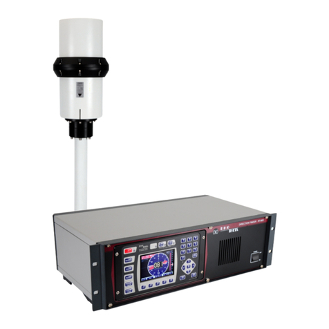
Rhotheta RT-500-M User manual

User Manual
RT-500-M

RT-500-M
RHOTHETA Page 2 of 168 User Manual
Edited by:
RHOTHETA Elektronik GmbH
Kemmelpark
Dr.-Ingeborg-Haeckel-Str. 2
82418 Murnau
Germany
Tel.: +49 8841 4879 - 0
Fax: +49 8841 4879 - 15
Internet: www.rhotheta.de
E-Mail: [email protected]
Copyright © RHOTHETA Elektronik GmbH
All rights reserved
-Issue: 2020/03/27 [Rev 1.07]
-Document-ID: 12-9-1-0002-3-1-64
-Valid for RT-500-M systems with revision [Rev 4.08] or higher
Note
The manufacturer reserves the right to make modifications to the product described here at any time
and without previous information.

RT-500-M
RHOTHETA Page 3 of 168 User Manual
Content
1Legend of Signal Words ...............................................................................................................5
2Safety..............................................................................................................................................5
2.1 General Safety Information.....................................................................................................................5
2.2 Basic Safety Instructions ........................................................................................................................6
3Legal Information ..........................................................................................................................7
3.1 Declaration of Conformity (EU)...............................................................................................................7
3.2 FCC Information (USA) ..........................................................................................................................7
3.3 ISED Information (Canada) ....................................................................................................................8
4General Description ......................................................................................................................9
5Quick Start ...................................................................................................................................10
6Overview ......................................................................................................................................14
6.1 Front View.............................................................................................................................................14
6.2 Rear View .............................................................................................................................................16
7Operation .....................................................................................................................................18
7.1 Bearing Page ........................................................................................................................................19
7.1.1 Bearing Indication ....................................................................................................................19
7.1.2 Bearing Operation....................................................................................................................23
7.1.3 Function Channel 16................................................................................................................37
7.1.4 Function Repeat ......................................................................................................................37
7.1.5 Function Clear..........................................................................................................................38
7.1.6 Function Autoset Squelch........................................................................................................38
7.2 Scan Page ............................................................................................................................................39
7.2.1 COSPAS-SARSAT Scan .........................................................................................................41
7.2.2 Monitoring ................................................................................................................................43
7.2.3 Fast Channel Scan (Licensed Option).....................................................................................49
7.2.4 Marine Scan.............................................................................................................................54
7.2.5 SAR Scan ................................................................................................................................57
7.2.6 Scan List ..................................................................................................................................63
7.3 Decode Page ........................................................................................................................................67
7.3.1 Selecting a COSPAS-SARSAT frequency ..............................................................................69
7.3.2 COSPAS-SARSAT List View...................................................................................................69
7.3.3 COSPAS-SARSAT Bearing View............................................................................................70
7.3.4 COSPAS-SARSAT Bearing and List .......................................................................................71
7.3.5 Export to Bearing Page............................................................................................................72
7.4 Setup Page ...........................................................................................................................................73
7.4.1 General ....................................................................................................................................73
7.4.2 Display .....................................................................................................................................82
7.4.3 System .....................................................................................................................................98
7.4.4 Interface .................................................................................................................................116
7.4.5 Service ...................................................................................................................................131
7.5 Other Operational Functions ..............................................................................................................140
7.5.1 Standby Mode........................................................................................................................140
7.5.2 Adjusting the Volume.............................................................................................................140
7.5.3 Adjusting of the Squelch........................................................................................................142
7.5.4 Dimming and Day/Night Mode...............................................................................................143

RT-500-M
RHOTHETA Page 4 of 168 User Manual
7.5.5 MOB (Man Over Board) Operation........................................................................................145
8Interfaces and Installation ........................................................................................................147
8.1 Power & I/O ........................................................................................................................................147
8.2 Necessity of a DC/DC-converter ........................................................................................................148
8.3 Antenna Unit (Connecting Cable DCU ÙAU) ...................................................................................149
8.3.1 Pinning Antenna Unit Connector ...........................................................................................149
8.3.2 Connecting Cable DCU ÙAU...............................................................................................149
8.4 NMEA COM-Interfaces.......................................................................................................................150
8.5 LAN Interface......................................................................................................................................151
8.6 USB Service Interface ........................................................................................................................152
8.7 Ground Connector ..............................................................................................................................152
8.8 Guideline for Optimal DF Antenna Position........................................................................................153
9Technical Data ...........................................................................................................................154
9.1 Electrical Characteristics ....................................................................................................................154
9.2 Mechanical Characteristics.................................................................................................................156
9.2.1 Mechanical Data ....................................................................................................................156
9.2.2 DCU Mounting Cutout............................................................................................................157
9.2.3 AU Mast Flange .....................................................................................................................157
10 Disposal within the European Union.......................................................................................158
11 Disposal outside the European Union.....................................................................................158
12 Maintenance and Cleaning .......................................................................................................159
12.1 Maintenance .......................................................................................................................................159
12.2 Cleaning..............................................................................................................................................159
13 Appendix ....................................................................................................................................160
13.1 Error Messages ..................................................................................................................................160
13.2 Warnings.............................................................................................................................................160
13.3 Setup Tree View (Settings).................................................................................................................161
13.4 Default / User System Configuration Table ........................................................................................162
13.5 Scan Page Tree View (Settings) ........................................................................................................164
13.6 Frequencies of Channels in Marine Band ..........................................................................................165
13.7 Channel Spacing UHF / VHF Air Band...............................................................................................166
13.8 Abbreviations ......................................................................................................................................167
14 Notes ..........................................................................................................................................168

RT-500-M
RHOTHETA Page 5 of 168 User Manual
1 Legend of Signal Words
Note
This symbol designates tips or additional notes that must be paid attention to and make work
easier.
Caution
Means that ignoring the instructions may lead to property damage or loss of data.
Warning
Means that ignoring the instructions, there may be a danger to health or life.
2 Safety
2.1 General Safety Information
RHOTHETA Elektronik GmbH is constantly trying to keep the safety standard of their products up to
date and to offer their customers the highest possible level of safety.
RHOTHETA products are designed and tested in accordance with the valid safety regulations. The
compliance with these standards is continuously monitored by our quality assurance system.
This product is tested and left the factory in perfect technical and safety-relevant condition. To
maintain this condition and to ensure safe operation, the user must pay attention to all instructions and
warnings given. For any questions regarding these safety instructions, RHOTHETA Elektronik GmbH
can be contacted at any time.
The observance of the safety instructions will help to prevent personal injury or damage caused by all
kinds of dangers. This requires that the following safety instructions must be read carefully and
understood before using the product, as well as observed while using the product. Other additional
safety instructions, such as for protecting persons, appear in relevant parts of the product
documentation and must also be paid attention to.
In addition, it is the responsibility of the user to use the product appropriately. The product RT-500-M,
a professional VHF direction finder system, shall not be used in any way that results in personal injury
or property damage.
The use of this product for other than its designated purpose or in disregard of the instructions of the
manufacturer is the responsibility of the user. The manufacturer takes no responsibility for the misuse
of the product.
The manufacturer is not liable beyond the scope of legal rules!
This guide is part of the product RT-500-M and must be kept with the product throughout its lifetime.

RT-500-M
RHOTHETA Page 6 of 168 User Manual
2.2 Basic Safety Instructions
Caution / Warning
Read and observe the following instructions, warnings and safety guidelines from the
manufacturer!
.
xAt all times, the local or national safety and accident prevention regulations must be
observed.
xWhen installing or operating with the product, always follow the manufacturer's instructions.
xOnly place the product on appropriate locations.
xDo not expose the product to environmental conditions (heat, humidity, wind load etc.) that
exceed the specified conditions in the manuals.
xUse only the manufacturer’s prescribed components and/or use only recommended
materials and do not change them. Any other use or unauthorized modifications to the
product will void the authorization to operate it.
xConnect only approved accessories kits or additional equipment.
xEnsure that the connections with information technology equipment, e.g. industrial
computers, comply with the IEC 60950-1/EN 60950-1 standards that applies in each case.
xThis product may only be opened by authorized personnel. The connector must always be
disconnected before opening.

RT-500-M
RHOTHETA Page 7 of 168 User Manual
3 Legal Information
3.1 Declaration of Conformity (EU)
Hereby RHOTHETA Elektronik GmbH declares that the product RT-500-M complies with the essential
requirements and other relevant provisions of:
xDirective 2014/53/EU relating to radio equipment (relevant for RT-500-M AU)
xDirective 2014/30/EU relating to electromagnetic compatibility (relevant for RT-500-M DCU)
xDirective 2014/35/EU relating to the making available on the market of electrical equipment
designed for use within certain voltage limits (relevant for RT-500-M DCU)
xDirective 2011/65/EU on the restriction of the use of certain hazardous substances in electrical and
electronic equipment (relevant for RT-500-M AU and RT-500-M DCU)
The full text of the Declaration of Conformity can be found at:
https://www.rhotheta.com/products/rt_500_m
3.2 FCC Information (USA)
Changes or modifications not expressly approved by the party responsible for compliance
(RHOTHETA) could void the user's authority to operate the equipment.
Note
RT-500-M AU has been tested and found to comply with the limits for a Class B digital device,
pursuant to part 15 of the FCC Rules. These limits are designed to provide reasonable protection
against harmful interference in a residential installation. This equipment generates, uses and can
radiate radio frequency energy and, if not installed and used in accordance with the instructions, may
cause harmful interference to radio communications. However, there is no guarantee that interference
will not occur in a particular installation. If this equipment does cause harmful interference to radio or
television reception, which can be determined by turning the equipment off and on, the user is
encouraged to try to correct the interference by one or more of the following measures:
xReorient or relocate the receiving antenna.
xIncrease the separation between the equipment and receiver.
xConnect the equipment into an outlet on a circuit different from that to which the receiver is
connected.
xConsult the dealer or an experienced radio/TV technician for help.
Note
RT-500-M DCU has been tested and found to comply with the limits for a Class A digital device,
pursuant to part 15 of the FCC Rules. These limits are designed to provide reasonable protection
against harmful interference when the equipment is operated in a commercial environment. This
equipment generates, uses and can radiate radio frequency energy and, if not installed and used in
accordance with the instruction manual, may cause harmful interference to radio communications.
Operation of this equipment in a residential area is likely to cause harmful interference in which case
the user will be required to correct the interference at his own expense.

RT-500-M
RHOTHETA Page 8 of 168 User Manual
3.3 ISED Information (Canada)
This device complies with Industry Canada’s licence-exempt RSSs. Operation is subject to the
following two conditions:
(1) This device may not cause interference; and
(2) This device must accept any interference, including interference that may cause undesired
operation of the device.
Le présent appareil est conforme aux CNR d'Industrie Canada applicables aux appareils radio
exempts de licence. L'exploitation est autorisée aux deux conditions suivantes : (1) l'appareil ne doit
pas produire de brouillage, et (2) l'utilisateur de l'appareil doit accepter tout brouillage radioélectrique
subi, même si le brouillage est susceptible d'en compromettre le fonctionnement.
A radio license must be obtained prior to possession and use of this scanner receiver.
Une licence radio doit être obtenue avant la possession et l’utilisation de ce récepteur de scanner.

RT-500-M
RHOTHETA Page 9 of 168 User Manual
4 General Description
The RT-500-M is a wideband radio direction finder system for professional use in maritime sector.
The system operates within a frequency range from 118 to 470 MHz (the whole range can be
unlocked to the full extend by using the options F1 – F4 listed below).
Designed for professional use under extremely rough conditions, the SAR standard version covers the
whole VHF marine band and all relevant distress frequencies, such as emergency frequencies 121.5 /
243 MHz, marine channel 16 (156.8 MHz) and all 19 frequencies of the international satellite search
and rescue system COSPAS-SARSAT (406 MHz). While locating a COSPAS-SARSAT EPIRB, the
direction finder can also decode and display its transmitted information (e.g. Beacon ID and GPS
Position). The wide frequency range and frequency steps of 5 kHz allow using the system not only for
search and rescue operations but also for detecting illegal vessels operating in a non-standard
frequency grid or using PMR (446 MHz) and LPD (433 MHz) radio transmitters. Therefore the system
is also widely used by police, coast guards and other maritime law enforcement organisations.
The MOB (Man Over Board) surveillance for the crew safety is a standard function of the RT-500-M.
The fine frequency steps (5 kHz) allow discovering hidden transmitters in the marine band and in the
additional UHF band.
RT-500-M Frequency Range
Standard Range Optional Extended Range
VHF emergency band
VHF marine band1
UHF emergency band
COSPAS - SARSAT
UHF FM band
118.000 … 124.000 MHz
154.000 … 163.000 MHz
240.000 … 246.000 MHz
400.000 … 406.092 MHz
406.100 … 410.000 MHz
F1: VHF air band
F2: extended VHF marine band
F3: UHF air band
-
F4: additional UHF FM band
118.000 … 136.992 MHz
137.000 … 224.995 MHz
225.000 … 399.975 MHz
-
406.100 … 470.000 MHz
Table 1. RT-500-M frequency ranges
The DF-system consists of two units: the bearing device AU (antenna unit) and the operating device
DCU (display control unit).
The antenna unit accommodates all the direction-finding electronics within its housing. Thus, short
signal paths with low loss and insensitiveness to external disturbing fields are achieved.
The display control unit indicates bearing signals and acts as an instrument for operating and
controlling the direction-finding system. External devices can be connected to the DCU, such as an
external speaker, a PTT (push-to-talk) switch, etc. It is also possible to input and read data coming
from various interfaces, such as external compass data via an NMEA interface. This allows the
integration of compass data into the bearing data, which can be indicated on display.
1Inclusive all maritime channels (ship / coast): channels 00 … 88 (156,000 … 162,025 MHz)

RT-500-M
RHOTHETA Page 10 of 168 User Manual
5 Quick Start
1. Connect the power supply to the DCU.
2. Establish the connection of the AU and the DCU.
(“Guideline for Optimal DF Antenna Position” can be found under 8.8)
Figure 1. General connection schematic
3. Any additional devices like external speaker, compass etc. can be also connected to the DCU.
For further information about the installation of the system please refer to chapter 8.
4. Push the ON/OFF button .
5. When the DCU is turned on, the ON/OFF button lights green and the DCU indicates the
loading screen (s. Figure 2).
Figure 2. Loading screen

RT-500-M
RHOTHETA Page 11 of 168 User Manual
After approximately 15 s the loading is completed and the indication changes to the “RT-500-
M” start screen for approx. 5 seconds (s. Figure 3).
Figure 3. RT-500-M start screen
6. As a final result, the bearing page is loaded (s. Figure 4). This is the first page that is displayed
when the system is started for the first time.
The next time the device is restarted, the last page that was used before the restart will be
loaded after the start screen.
To turn off the DCU hold the ON/OFF button pressed for about 2-3 seconds.
Figure 4. Start page (bearing page)
7. Adjust the needed main bearing frequency (the default frequency after first system start is
marine channel 16):
oPush the hotkey “Freq.Ch.” (s. field “A”, Figure 4).

RT-500-M
RHOTHETA Page 12 of 168 User Manual
Figure 5. Frequency input dialog
oType the desired frequency into the lower input field “Standby … [MHz]” by using the
number-keys of the keypad (s. field “B”, Figure 5) and confirm by pressing “OK” (s. field
“C”, Figure 5).
The system will accept only inputs within the permitted frequency ranges.
oPress the “Swap” hotkey (s. field “D”, Figure 5) to set the new frequency to main
bearing frequency (“Active”).
Figure 6. New frequency Input
oTo input a maritime channel number, push the hotkey “Channel” (s. field “E”, Figure 6)
and proceed by typing the number and pressing “OK”.
oTo select a desired Cospas-Sarsat frequency (channel ABC – channel RS) from a
drop-down menu press the “CP-SS” hotkey (s. field “F”, Figure 6). Confirm the desired
frequency with “OK”.
oPress “HOME” button to open the “Bearing” page.

RT-500-M
RHOTHETA Page 13 of 168 User Manual
8. Adjust the squelch level:
oUse the arrow keys to increase or decrease the squelch level manually
(the squelch indicator will move up or down in one-percent steps and show the current
value).
Figure 7. Squelch level adjustment
oBy pressing the “Autoset SQL” hotkey (s. field “G”, Figure 7) the level of the squelch
can be automatically adjusted to a suitable value for the current signal level.
For more information on the setting of squelch please refer to chapter 7.5.3.
After all settings the system operates at the entered frequency.

RT-500-M
RHOTHETA Page 14 of 168 User Manual
6 Overview
6.1 Front View
Figure 8. DCU front view
Front Control Elements
Pos. Element Function Description
Switches the system on/off.
When the system is turned on, the key is highlighted in green.
In the case of an error the key will blink red.
Provides the standby operation to save energy.
By pressing this button, the standby is activated, and the button is
highlighted in orange.
While in standby, the brightness of the display’s backlight is driven
down to a defined value (configurable in the “Setup” page, s. 7.4.2.8),
but the system continues monitoring the corresponding (emergency)
frequency. The display will be turned on again if an event occurs (e.g.
signal level rises above squelch level, alarm occurs, scan algorithm
finds an active frequency).
Pressing any button will return the system from standby to normal
operation mode (the function of the pressed button will not be
executed).
The volume adjustment button contains two keys (+ and -).
Pressing any of the two keys opens a dialog for adjusting the internal
and external speakers (s. 7.5.2).
Switches the volume off/on (mute function).
The mute-status is indicated by the orange highlight of the button.

RT-500-M
RHOTHETA Page 15 of 168 User Manual
The volume can be turned on by pressing the same button again.
While the mute function is activated, it is still possible to increase or
decrease the volume without producing any sound (using the button for
volume adjustment, s. ).
The brightness adjustment button contains two keys (+ and -).
Pressing any of the two keys opens the dialog window for brightness
adjustment of the TFT-display backlight, status keys (labeled “Keys” in
the “Adjust Brightness” dialog) (colored highlighting of buttons ,
and ) and the white illumination of buttons / legends (s. 7.5.4).
The squelch adjustment button contains two keys (+ and -).
Pressing any of the two keys opens the dialog window for adjusting of
the squelch level (s. 7.5.3).
Activates the “Man-Over-Board” dialog, if GPS data is available (s.
7.5.5).
5“ TFT full-color
display
Shows the corresponding data content of the current page or dialog.
Hotkeys for activating variable functions.
The assignment of the keys differs depending on the page or dialog.
Sensor of
brightness
Measures the ambient brightness to automatically adjust the brightness
of the TFT display, status keys (labeled “Keys” in the Adjust Brightness”
dialog) and buttons/legends.
Returns one step back in a menu or leaves a dialogue or an adjusting
field without storing changed parameters.
Confirms an input or selection.
Leaves a dialogue or an adjusting field and stores changed parameters.
By pressing this button, the system returns to the bearing page from
any other page or dialog, without storing changed parameters.
The arrow keys provide the navigation and selection within the menu or
selection field.
Furthermore, they allow increasing or decreasing of some values (e.g.
squelch level).
Numeric keys for direct numeric input.
Navigation keys for switching between the pages.
Within the “Setup” page, the navigation keys have different functions
due to the large number of possible settings.
Table 2. Front control elements

RT-500-M
RHOTHETA Page 16 of 168 User Manual
6.2 Rear View
Figure 9. DCU rear view
Interfaces
Pos. Element Function Description
Communication
Ports:
COM1
COM2
COM3
NMEA 0183 Bus (RS422 / RS232):
xConnection for input of external data, such as compass, GPS,
remote control, etc.
xConnection for output of bearing data, e.g. for map plotter, PC
etc.
When connecting to input use either RS232 Rx or RS422 Rx (not both)!
For more information s. 8.4.
AU
Antenna connector:
Connection between DCU and AU via cable
For more information s. 8.3.
Screw Cover
Waterproof protection cover for USB connector and replaceable fuses
Opening of the screw cover should be done in a dry room to prevent the
ingress of moisture into the interior of the DCU.
POWER + IO
Source connector:
xConnection for power supply
xConnection for external speaker
xConnection for self-bearing suppression (SBS / PTT)
xConnection for audio line out

RT-500-M
RHOTHETA Page 17 of 168 User Manual
xContacts for alarm relay
xContacts for squelch out
For more information s. 8.1.
Ground connector:
Connection of the DCU to the ground of the ship
Thread/screw M5
For more information s. 8.7.
LAN LAN connector for network communication
For more information s. 8.5.
Label Label with identifying information about the direction finder.
Speaker Waterproof internal speaker
USB
(Only Service)
USB 2.0 port:
Used only for service / manufacturing purposes.
For more information s. 8.6.
Pressure
Compensation
Element
Equipped with a Gore-Tex membrane, the pressure compensation
element prevents over- and underpressure in the DCU.
Fuses
Replaceable fuses:
F1: T3A/127V (Littelfuse 154003.T)
F2: T5A/127V (Littelfuse 154005.T)
F3: T1A/127V (Littelfuse 154001.T)
F4: T0.5A/127V (Littelfuse 154.500T)
Note
It is recommended to use an additional external fuse: T2A
Table 3. Interfaces
Warning
The voltage supply is not galvanically isolated from the frame (s. 8.2).

RT-500-M
RHOTHETA Page 18 of 168 User Manual
7 Operation
The RT-500-M is operated using the keys placed around the display.
In normal bearing mode, the keys call up common functions directly, opening the corresponding dialog
window.
The basic structure of a DCU Page is as follows:
Figure 10. Basic structure of pages
The different pages are listed on the top line of the screen and the active page is highlighted in light
blue. Switching between pages is done via the corresponding navigation keys, which are located
directly above the page names (s. field “A”, Figure 10).
The top line of the screen is the same for all pages except the “Setup” page, which contains all the
necessary system setup options.
The hotkeys differ from page to page to provide page-specific functions or settings. Activate the
hotkey function or setting by pressing the corresponding hotkey (s. field “B”, Figure 10).

RT-500-M
RHOTHETA Page 19 of 168 User Manual
7.1 Bearing Page
The bearing page is the main page of the RT-500-M display unit as it provides the bearing information,
settings and status reports at a glance.
This page can be opened by pressing the button “HOME“ from any other page or dialog.
7.1.1 Bearing Indication
The “Bearing” page has the following structure (s. Figure 11).
Figure 11. Bearing display
Indication on Bearing Page
Pos. Element Meaning / Description
Top line Navigation line of the screen, which allows switching between pages
(“Bearing”, ”Scan”, “Decode” and “Setup”).
Frequency
indication
Section for frequency/channel indication during bearing and scanning.
The active frequency is displayed in white color.
If the scanning function is activated, the currently active frequency (or
channel) is displayed in green, and the other frequencies, monitored by
the scanning algorithm, are displayed in gray.
If the “Repeat” hotkey (s. ) is pressed, the old frequency value will
also be shown in gray.
If there is not enough space to show all frequencies, only a subset of
the frequencies around the currently active frequency will be displayed.
Alarms / Errors /
Warnings
Section for indicating any faults in the system, alarms and/or warnings
(s. 7.1.2.1).

RT-500-M
RHOTHETA Page 20 of 168 User Manual
Frequency /
Channel hotkey
Pressing the “Feq.Ch.” hotkey will activate the frequency/channel input
dialog (s. 7.1.2.2).
If no input is detected for about 10 seconds, the dialog will be closed
automatically. This waiting time can be changed in the “System” menu
of the “Setup” page (s. 7.4.3.6).
Memory hotkey
Pressing the “Memory” hotkey will activate the memory dialog (s.
7.1.2.3).
The memory dialog provides a list of saved frequencies or channels,
which facilitates restoring any frequency from the list to the active
bearing mode.
Frequencies/channels (max. 8 frequencies) to be scanned in the mode
“Fast Channel Scan” (available only with unlocked option), can be
selected in the “Memory” dialog.
Channel 16 Instant access to most common maritime emergency channel (or
emergency frequency 121.500 MHz).
Repeat hotkey
Calls up last valid bearing, heading and level values.
The last bearing clock in the lowermost line of the digital bearing display
(s. Figure 13) shows the time elapsed since the last valid bearing
interruption.
Clear hotkey Resets the internal value of the bearing averaging memory.
Mutes the acoustic alarm (if such occurred, s. 7.1.2.1).
Autoset SQL /
Squelch hotkey
Activates the automatic squelch level adjustment for the active
frequency (for further information s. 7.1.6).
Escape button
Pressing this button while a dialog is open, will close the dialog without
saving changes.
If no dialog is open, pressing this button will go back to the last
activated page. The “Bearing” page is the end-point. Pressing this
button on the “Bearing” page will have no effect when no dialog is open.
Monitoring/scanning operation will continue onto the next
frequency/channel upon pressing the “ESC” button, if e.g. currently no
data is being received on present frequency.
Home button
Pressing this button always leads to the “Bearing” page (home page)
from any other page or dialog.
If any scan is running, a dialog for leaving the scan will be opened when
the “Home” button is pressed.
Arrows
“Up” and “Down”
and the
“OK” button
The squelch level of the main bearing frequency/channel can be
adjusted manually by using the arrow buttons (this is only possible if the
main frequency is active).
If any scan mode is active, pressing one of these buttons will open the
squelch dialog (s. 7.5.3).
If no dialog is open, the “OK“- button will not have any effect on the
“Bearing” page. Whereas inside a dialog this button is used to confirm
an input and close the dialog.
Additional data
indication
Section for indicating additional data, such as activated or deactivated
additional hardware or elapsed time indication for the next awaited
Cospas-Sarsat pulse.
Other manuals for RT-500-M
1
Table of contents
Other Rhotheta Camera Accessories manuals