Rhotheta RT-100 User manual

Manual
RT-100
Emergency Receiver
Microprocessorcontrolled Surveillance Receiver
(Man Overboard)
with two frequencies and special additional functions

RT-100 Emergency Receiver
Page 2 of 11
Edited by:
RHOTHETA Elektronik GmbH
Kemmelpark
Dr.-Ingeborg-Haeckel-Str. 2
82418 Murnau
Germany
Tel.: +49 8841 4879 - 0
Fax: +49 8841 4879 - 15
Internet: www.rhotheta.de
E-Mail: [email protected]
Copyrights © RHOTHETA Elektronik GmbH
All rights reserved
Issue: [2011/03/31] [Rev 1.06]
HINT
The manufacturer reserves on making modifications at any time and without previous
information of the product described here.

RT-100 Emergency Receiver
Page 3 of 11
Index
Common Hints ............................................................................................ 3
Operation .................................................................................................... 4
Connecting additional devices and power ............................................... 7
Technical Data ............................................................................................ 8
Declaration of Conformity ......................................................................... 9
1 Common Hints
Thank you for buying the RHOTHETA RT-100 Emergency Receiver. The RT-100
Emergency Receiver is a professional Man-over-board surveillance system for the
international ELT emergency frequency. In combination with man-carried emergency
transmitters as the PLB, high security concerning an unnoticed man-over-board scenario
will be obtained.
At this place we would like to ask you to read the User Manual attentively in order to
avoid possible problems caused by incorrect handling.

RT-100 Emergency Receiver
Page 4 of 11
2 Operation
Front view RT-100 Emergency Receiver
2
1
9
8
7
3
4
5
6 10
11

RT-100 Emergency Receiver
Page 5 of 11
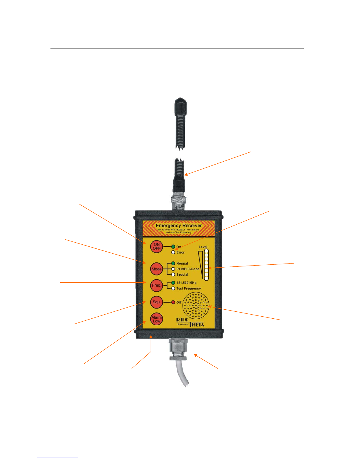
(1) ON/OFF-switch of the RT-100 Emergency Receiver. After a short switch-on system
test the device is ready to operate. The green LED will flash when switched on.
(2) When operating a continuous self-diagnosis is executed. In case of detecting an
internal fault the red ERROR-LED will flash. The RT-100 Emergency Receiver is
not working properly anymore.
(3) The Mode-button is used for selecting two different modes of operation. The
selected mode will be stored lasting until a new change.
Normal
When switched to this mode the RT-100 Emergency Receiver works as a
normal receiver. Each received signal on the active frequency will trigger alert.
In case of an alarm always an acoustic check should be made, if it is either the
typical PLB/ELT howling sound or a false alarm caused by rare, but occurring,
short transmissions of pilots or strong disturbing signals.
PLB/ELT-Code.
In this mode alert will be triggered only if a PLB/ELT-code signal with typical
downsweep is received (criteria of recognition are listed in chapter Technical
Data). For triggering alert a certain receiving field strength is required fo
r
analysing and recognising the modulation. At the beginning of an alarm an
acoustic beep will be given 25 times as additional signal. (The display LED
“Special” has no function)
(4) The Freq.-button is used to adjust the active receiving frequency.
121.500 MHz
This is the international emergency frequency. All PLB/ELT emergency
transmitters are working on this frequency. A green LED indicates that this
frequency is active.
Test Frequency (see chapter “Technical Data”)
This second frequency is used only for testing purposes in combination with a
transmitter working on the same frequency, in order not to trigger alert at others
(e.g. SAR etc.). A red flashing LED indicates (also as warning) wether this test
frequency is activated.
(5) The Squ.-button switches the squelch-function (ON/OFF). This function is used
mainly for checking the receiver. If the green Off-LED is lit, the squelch is switched
off and an acoustic noise on the speaker can be heard. This function does not
affect the squelch level or triggers alert.

RT-100 Emergency Receiver
Page 6 of 11
(6) The Alarm-Low-button disables (if alert is triggered) resp. enables internal/
external speakers; in addition the switching contact of the alarm-relay is also
deactivated. If there is no alarm, this function will be switched on automatically afte
r
60 sec. in order to assure warning after a forgotten switch-off.
(7) The 16-stepped level indicator displays the field strength of the incoming signal.
The field strength is also a relative measure for the distance to the transmitter. I
f
there is a level value between two LEDs, the next upper LED will flash.
(8) Integrated speaker indicates alarm and gives an acoustic control of the incoming
signal. Additionally each registered touch of the buttons will be acknowledged by a
short beep.
(9) At this position, after removing the lower cover (for this you will have to open first
the two screws), a potentiometer for adjusting the squelch level is situated. The
squelch has to be adjusted such insensitive that it is guaranteed that no strong
disturbing signals will be received. When adjusting, it is very important to change
into the “Normal” mode in order to hear the actual squelch level.
Turning the potentiometer clockwise => squelch less sensitive
Turning the potentiometer anticlockwise => squelch more sensitive
(10) Connecting cable for power supply and other additional devices.
(11) Receiving antenna with BNC-connector

RT-100 Emergency Receiver
Page 7 of 11
3 Connecting additional devices and power at
the connecting cable
3.1 Power
(+12 V … 24V DC) = colour red, (GND) = colour black
3.2 Additional speaker, audio exit
An additional external speaker may be connected (8 minimum) at the connecting
cable:
(Speaker +) = colour orange, (Speaker - ) = colour brown.
3.3 Relay contact
The Emergency Receiver contains a relay which is switching a contact between the
cables colour green and colour yellow, if alarm is triggered.
Optional: Connection Table for Sub-D-Connector
Signal Pin
GND 5
+12 V ... 24 V 9
Speaker - 1
Speaker + 6
Relay contact 2
Relay contact 7
not used 3, 4, 8

RT-100 Emergency Receiver
Page 8 of 11
4 Technical Data
Dimensions: width x height x depth:
85 mm x 115 mm x 35 mm (without antenna)
Weight: 350 g
Temperature range: -20 °C ... +60 °C
Protective system: IP 65 (dustproof and splashproof)
Sensitivity: < 0.5 µV at antenna input
Receiving frequency: 121.500 MHz (channel 1 / ELT frequency)
121.650 MHz (channel 2 / test frequency)
Criteria of ELT recognition: audible AM-modulated howling, downward;
LF-range within 300 Hz ... 1600 Hz,
LF-range 700 Hz minimum,
time of repetition: 250 ms ... 500 ms,
LF/25ms: -10 Hz ... –250 Hz
Audio exit: max. 8 Vss (speaker > 8 )
Relay contact (NOC): floating, carrying capacitiy max. 0.5 A / 10 W
Current Drain Standby: 80 mA
Alarm + ext. speaker (8 ): 400 mA
Operating voltage: +12 V … 24 V DC (± 20%)

RT-100 Emergency Receiver
Page 9 of 11
5 Declaration of Conformity

RT-100 Emergency Receiver
Page 10 of 11
Own notes:

RT-100 Emergency Receiver
Page 11 of 11
Table of contents
Other Rhotheta Receiver manuals
Popular Receiver manuals by other brands

HydroLynx Systems
HydroLynx Systems 5052RD-K instruction manual

Broadata Communications
Broadata Communications LinkBridge LBC-HDBT-R-DG user manual

Black
Black BLK-HDEXT Quick installation guide

Phonocar
Phonocar vm 032 instruction manual

Pioneer
Pioneer Elite VSX-43TX operating instructions

Pansat
Pansat 3500SD Capacitor Replacement Guide