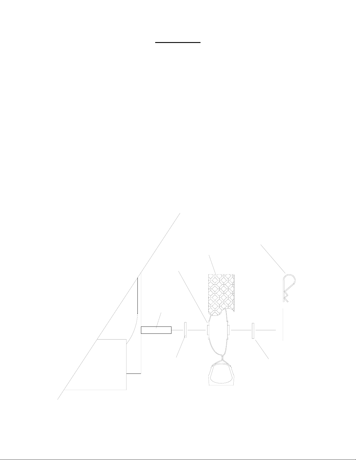
Rich Way Pestifoamer PF-6 Series User manual

Installation & Operation Manual
Pestifoamer
®
Models PF-6 &
PF-10 G Series

Thank you for purchasing a Richway Pestifoamer, foam application system. By following
this installation, use, and maintenance guide carefully, your unit will provide years of
satisfactory service.
Richway Industries Ltd. makes a continuing effort to improve its products. As such, we
reserve the right to make improvements without obligations to add them to machines
already in the field.
Please take a moment to fill out the following for future reference:
Model #:
Serial #:
Series: G
Date of Purchase:
Purchased From:
Form Number - PFG-397.doc

Table of Contents
SafetyFirst 3
Assembly 6
Here'sHowItWorks 7
Components 10
PowerUnit 10
Compressor 10
Agitation Valve 11
Foam/Liquid Valve 11
Tank Exhaust Assembly 11
DiskCheckValve 11
Siphon Breaker 11
Anti-Siphon Valve 11
Foam Head 12
Ground Fault Circuit Interrupter 14
Tank 16
CapAssembly 16
Tank Strap Catch 16
Foam Hose 16
Treating Tool 16
Operation 18
Mixing Foam 18
Mixing Termiticide 19
Treatment Procedure 19
Maintenance 20
Filter/Strainer 20
Foam Head 21
CompressorFilter 21
Siphon Breaker 21
Anti-Siphon Valve 22
Preventative Maintenance 24
Storage 24
Drain/Rinse Procedure 24
Trouble Shooting 25
Appendices 26
Flow Diagram PF-10 26
Pestifoamer Wiring 27
Warranty 29
2

IMPORTANT SAFETY PRECAUTIONS AND PROCEDURES
WARNING! Pesticides, termiticides and other chemical mist or liquid can cause
permanent eye, skin or lung damage or death. Always wear proper
protective clothing, goggles, aspirator, gloves or other chemical
protective garments as recommended by the label of the pesticide
you are using.
Follow chemical manufacturers' label directions when using the Pestifoamer. Do not vary
recommended rates.
When using the Pestifoamer and a leak is detected anywhere in the system, STOP
APPLICATION AND SHUT-OFF POWER UNIT IMMEDIATELY! Failure to observe
these precautions could result in severe bodily injury, including death in extreme
cases.
CAUTION! 1. Connect this unit to a three prong extension cord and only a
properly grounded three prong outlet.
2. Do not open tank when unit is in operation.
3. Never operate without power unit cover in place.
4. Never operate this machine outdoors in the rain or in a wet
area.
5. Do not disassemble. Disassembly or attempted repairs, if
accomplished incorrectly, can create electrical shock hazards.
Only qualified personnel should perform repair service.
6. Do not remove cover while connected to electrical source.
7. Do not remove foam hose without releasing pressure by opening
treatment tool.
8. Secure coupler cap to foam head outlet coupler whenever foam hose
is disconnected.
9. Secure coupler plug to foam hose coupler whenever foam hose is
disconnected.
10. Do not use this machine in or near an area where it can fall or
be pulled into water or other liquids.
11. Do not reach for this machine if it has come into contact with
liquid. Unplug immediately.
3

12. Never operate this unit with a damaged cord or plug. Discontinue
use if the cord is not working properly or if it has been damaged.
13. This machine should never be left unattended when plugged in.
14. Always unplug this machine immediately after use and store in
a dry place.
15. Close supervision is necessary when this product is used near
children or invalids. Never allow children to operate this
machine.
16. All electrical components generate heat. To avoid serious
burns never touch internal components immediately after use.
17. Do not operate this product in or near explosive atmospheres
or where aerosol (spray) products are being used.
18. The air compressor in this unit is thermally protected and can
automatically restart when the protector resets. Always disconnect
power source before servicing.
19. Wear safety glasses, goggles and all proper clothing when
operating or servicing this machine. Always read and follow
manufacturers' recommendations when handling any chemicals.
Tank
The tank is pressurized with air, from the compressor, to force liquid solution to the foam
head. DO NOT attempt to remove tank cap, for any reason, while the Pestifoamer is
turned on or plugged into an electrical outlet. DO NOT open tank cap until sound of air
escaping from exhaust valve, in power unit, has stopped. Remove cap slowly. Before
operation, secure tank cap assembly to tank.
When the Pestifoamer is turned off, pressure remains in the foam hose. Release all
pressure by opening the treatment tool, allowing pressure to exhaust, before attempting to
remove foam hose.
Compressor Relief Valve
The pressure relief valve has been set at 20 psi. Periodically check for proper operation.
Power Unit Cover
Remove power unit cover only when power is turned off and unit is unplugged.
4

Use of Extension Cords
Use only a heavy duty, grounded extension cord plugged into a properly grounded outlet
(minimum of 14 gauge for a 25' cord & 12 gauge for up to 100').
Ground Fault Circuit Interrupter
Test before each use. See COMPONENTS section for additional information.
1 7/8" Hair Pin
P-0974
7
/16 Flat Washer
P-0172
8" Wheel
P-0342 7/16 Flat Washer
P-0172
Tank Strap PF-6
P-0690
Tank Strap PF-10
P-0691
Axle
P-0402
Cap Assembly (THR) 1) 1/8" 2) 1/4"
P-0965
6 Gallon Tank (Threaded) - PF-6
P-0951
10 Gallon Tank (threaded) - PF-10
P-0953
Handle - Round
P-0379
1/4 X 1 7/8" Pin
P-0975
1 7/8" Hair Pin
P-0974
1 7/8" Hair Pin
P-0974
3/8" Grommet
P-0696
1/4" Grommet
P-0695
3/16" Grommet
P-0694
Power Box (PFG)
P-1087
FIGURE 1 - Pestifoamer Model PF-6 Assembly
5

ASSEMBLY
No tools are required to assemble your Pestifoamer. Units are shipped without the handle,
axle and wheels installed.
Axle and Wheels
1. Slide the axle shaft through holes in the lower rear of the power box.
2. Install 7/16” flat washer onto axle.
3. Slide wheel onto axle.
NOTE The Pestifoamer wheels have an offset center hub. Install the
wheels so that the offset hub prevents the wheel from rubbing on
the power box.
4.
5.
Secure wheel to axle with 7/16” flat washer and hair pin clip.
Repeat this procedure for the remaining wheel.
8" Wheel
Flat washer
Offset To Inside
Axle
Flat washer
1 7/8" Hair Pin
FIGURE 2- Pestifoamer 8” Wheel Installation
6

Handle Installation
Place handle into handle mounting hole (see figure 4 page 10). Secure Handle with ¼ X 1
7/8” pin and hair pin.
Foam Hose
Each Pestifoamer is equipped with 20 feet of 3/4" ID foam hose. This hose is attached to
the foam outlet coupler, located at the lower, left, rear of the machine. Always secure
coupler levers with the hair pins provided.
Caution! To prevent accidental spillage or breakage, disconnect hose, install
dust cap onto outlet and plugs into hose assembly and secure with
pins, before transporting machine. Do not attempt to transport
machine with the foam hose attached. Disconnect foam hose
assembly, and secure, before moving machine over obstacles such as
stairways, curbs, etc.
WARNING! When the Pestifoamer is turned off, pressure remains in the hose.
Release all pressure by opening the treatment tool, allowing pressure
to exhaust, before attempting to remove foam hose.
HERE'S HOW IT WORKS....
The PF-6 utilizes a pressurized tank system. A 115 volt AC compressor, located in the
power box (operates up to 20 psi), pressurizes the solution tank, which forces liquid back
into the power unit. Air and liquid are combined inside the power box to produce foam.
This design provides high foam output with a low electrical power requirement.
The operator combines water, foam concentrate and termiticide in the tank. Foam is
generated in the foam head, which is inside the power unit. The foam hose connects the
unit directly to a large orifice treating tool.
Air
Air from the compressor is routed to the tank via the 3/8" OD tubing. Air flows from the
3/8" OD airline, attached to the tank cap. This pressurizes the tank, to push the liquid into
the foam head located in the power box.
The agitation valve directs air from the compressor, through the 3/16" OD tubing, to the
bottom of the tank to mix water, foam concentrate, and termiticide solution.
The foam/liquid valve controls air flow to the foam head. When in the "foam" position, air
flows to the foam head. In the "liquid" position, air flow to the foam head is stopped. This
allows only liquid to be discharged from the foam chamber into the hose and tool.
7

The 3/8" airline to the tank is connected to a diaphragm exhaust valve. When the power is
turned off, this valve opens to rapidly release air pressure in the tank.
WARNING! When the Pestifoamer is turned off, pressure remains in the hose.
Release all pressure by opening the treatment tool, allow all pressure
to exhaust, before attempting to remove foam hose.
Liquid
The air pressure in the tank forces liquid into a 1/4" OD pick-up tube. Liquid is routed
through 1/4" OD tubing to the foam head. The liquid flow rate is 3 minutes per gallon.
PF-6
The liquid tubing from the tank to the foam head is equipped with a siphon breaker
system which will prevent the liquid from siphoning out of the tank, when the
pestifoamer is turned "off".
PF-10
The liquid tubing from the tank to the foam head is equipped with an anti-siphon
valve which will prevent the liquid from siphoning out of the tank, when the
pestifoamer is turned "off". See Appendix 1 page 26.
8

Compressor
Tank
Exhaust
A
ssembly
B
A
Foam Head
Assembly
Disk
Check
Valve
Gauge
Foam/Liquid
Valve
6 Gallon
Tank
Assembly
Liquid
Air
Disk
Check
Valve
Cap
Assembly
Agitation
Valve
Siphon
Breaker
FIGURE 3 - Pestifoamer Model PF-6 Flow Diagram
9

COMPONENTS
The Pestifoamer consists of three basic components: power unit, tank, and foam hose.
Power Unit
WARNING! Before attempting to open power unit cover, be sure machine is
unplugged to prevent electrical shock. Do not operate
Pestifoamer without cover.
Compressor
The 115 volt, AC compressor is used to pressurize liquid in the tank and force it
into the foam head where it is mixed with air to produce foam. The compressor
pumps air through the 3/8" OD airline into the tank. During operation, with the
treatment tool open, the Pestifoamer will operate at less than 20 psi, often as
little as 7 to 10 psi.
NOTE: The compressor is equipped with a relief valve that has been
factory set at 20 psi. This valve prevents over pressurization of
the components. Check its operation periodically. Do Not adjust
relief valve above 20 psi.
Handle Mounting Hole
Agitation Valve
LIQUID
Foam/Liquid Valve
FOAM
Air Pressure Gauge
(should not exceed 20 psi)
P-0297
On/Off Rocker Switch
P-1086
OFF
ON
FIGURE 4 - Pestifoamer Controls
10

Agitation Valve
The Pestifoamer has a tank agitation system. The agitation valve (located on the
top of the power unit) is turned counter-clockwise to "agitate". When in "agitate"
position, air is introduced near the bottom of the tank to mix the materials in the
tank. If you do not agitate at the time of mixing, there may not initially be foam at
the treatment tool and/or the termiticide may not be properly mixed in the solution.
IMPORTANT It is only necessary to agitate for only a short time, 10 seconds,
to prevent excessive foam generation in the tank. Over
agitation of the foam mixture will result in foam being released
from the diaphragm exhaust valve.
Foam/Liquid Valve
The foam/liquid valve controls air flow to the foam head. When in the "foam"
position, air flows from the tank to the foam head. Normal foaming operations
require that this valve be in the "foam" position. In the "liquid" position, air flow to
the foam head is stopped, while pressurizing the tank. In this position, only liquid is
pushed out of the machine. Use the liquid setting only when draining the tank.
Tank Exhaust Assembly
When the Pestifoamer is turned off, this system exhausts air from the tank. DO
NOT open tank cap until sound of air escaping from this exhaust system in power
unit has stopped. DO NOT attempt to remove tank coupler cap, until all air has
been exhausted from this system. Open tank slowly, to relieve any remaining
pressure.
Disk Check Valves
One disk check valve is used to prevent tank materials from reaching the
compressor. Another disk check valve is used to prevent liquid from the foam head
from being exhausted through the tank exhaust valve.
Siphon Breaker Model PF-6
Model PF-6 Pestifoamers are equipped with a siphon breaker to prevent liquid
flow when the machine is "off". When the Pestifoamer is turned on, this system
will allow fluid to flow to the foam head. See siphon breaker system maintenance
on page 21 for important information.
Anti-siphon Valve Model PF-10
Model PF-10 Pestifoamers are equipped with a normally closed solenoid valve to
prevent liquid flow when the machine is "off". When the Pestifoamer is turned on,
this valve will open to allow fluid to flow to the foam head. See anti-siphon valve
maintenance on page 22 for important information.
11

Foam Head
The foam head is located inside the power unit. Air and liquid are mixed in the foam
head to produce the foam, which is then pumped out through the hose to the
treating tool. If needed, the entire foam head assembly may be disassembled for
cleaning (see figure 11 page 20). Be careful not to over tighten outlet coupler when
re-installing foam head. If over tightened, this fitting may break.
1/4mpt X 3/8tube Elbow (QC)
P-0360
3/8" Tubing blk nylon (per foot)
P-0349
1/4mpt X 3/8tube Elbow (QC)
P-0360
1/4mpt X 3/8tube Elbow (QC)
P-0360
3-way Solenoid Valve (115V)
P-0970
Diaphragm Exhaust Valve
P-0971
1/4" Close Nipple
P-0052
3/8 Disk Check Valve
P-0675
3/8" Tubing blk nylon (per foot)
P-0349
1/4mpt X 3/8tube Straight (QC)
P-0699
1/8mpt X 1/4mpt Adapter (Brass)
P-0930
1/8mpt X 1/4tube Straight
P-0633
1/4mpt X 3/8tube Elbow (QC)
P-0360
3/16 Tubing blk nylon (per foot)
P-0698
1/4tube X 3/16tube Union (QC)
P-0697
1/4 Tubing blk nylon (per foot)
P-0348
1/4mpt X 1/4tube Elbow (QC)
P-0395
1/4tube Union Tee
P-0564
Agitation Valve
Assembly
1/4" 3-way Ball valve
P-0678
3/8" Tubing blk nylon (per foot)
P-0349
Tank Exhaust Valve
Assembly
1/4mpt X 1/4tube Elbow (QC)
P-0395
1/4" 4-way Cross
P-0053
Relief Valve - 20 psi
P-1089
Compressor Fittings
Assembly
Foam/Liquid Valve
Assembly
1/4mpt X 3/8tube Elbow (QC)
P-0360
1/4" 2-way Ball valve
P-0679
3/8tube Cross (QC)
P-1088
FIGURE 5 - Pestifoamer Power Unit Components
12

B
A
1/4" 3-way Ball valve
P-0678
Cap (foamhead)
P-0216
Foam Outlet
3/4" Coupler (f)
P-0209
Tank Exhaust Valve
1/4" 2-way Ball valve
P-0679
Plug - 3 Prong
(panel mount)
P-0407
Back Panel (PFD)
P-0680
GFCI (panel mount)
P-0406
Diaphragm Compressor
(115V)
P-0340
Compressor Filter (PF)
P-0351
FIGURE 6 - Pestifoamer Back View
Tank Cap Assembly (THR) 1) 1/8" 2) 1/4"
P-0965
Handle - Round
P-0379
6 Gallon Tank (Threaded) - PF-6
P-0951
10 Gallon Tank (Threaded) - PF-10
P-0953
Catch/Strike
P-0689
Tank Strap - PF-6
P-0690
Tank Strap - PF-10
P-0691
1/4-10 Thumb Screw
P-0961
3/4" Coupler (F)
P-0209
3/4" Coupler Cap (DC)
P-0688
Hand Grip
P-0377
Louver Filter
P-0906
Power Box Cover (PFD)
P-0692
FIGURE 7 - Pestifoamer Side View
13

Ground Fault Circuit Interrupter
The Ground Fault Circuit Interrupter (GFCI) is panel mounted in the lower rear of
the power unit (see figure 6).
The Pestifoamer is equipped with a Ground Fault Circuit Interrupter (GFCI), to
protect against electrical shock hazards caused by ground faults where
permanent protection is unavailable. Always use a 3-wire grounded extension
cord, because a ground provides additional protection against electrical shock
hazard.
To operate this unit:
CAUTION! The GFCI device must be tested daily, to assure proper operation.
1. Plug a 3-wire extension cord into receptacle on power unit. Connect
extension cord only to a three prong, properly grounded outlet.
2. Press TEST MONTHLY button. This will simulate an electrical ground
fault for test purposes. Proper functioning of the GFCI is indicated when
the RESET button pops out and the Pestifoamer stops running.
3. Turn unit on.
4. If the RESET button trips (pops out), the leakage to ground in the
Pestifoamer is excessive and must be checked.
WARNING! If the GFCI fails to trip when the TEST button is pressed or fails to
reset, the GFCI may be defective, a ground fault may exist in the
Pestifoamer or the circuit to which it is connected. Do not bypass the
GFCI if this condition occurs, a real shock hazard may exist.
CAUTION!
1. Do not connect Pestifoamer to a power cord longer than 100 feet.
2. This machine is to be used only with 120V/60Hz electrical outlets.
3. Ground fault circuit interrupters do not protect against electrical shock
resulting from contact with both line and neutral wires of an electrical
circuit.
4. Do not use where water may enter the GFCI case.
5. The GFCI is designed as a protective device, do not use as an on/off
switch.
6. Test GFCI operation before each use to ensure correct operation.
14

3/16tube Union Elbow (QC)
P-0681
1/4" Tubing Nat Poly (17 1/2")
P-0399
1/8mpt X 1/4tube Straight (QC)
P-0633
Cap Assembly 1) 1/8 2) 1/4
P-0965
1/4mpt X 3/8tube QC Elbow
P-0360
1/4" Tubing Nat Poly (17 1/2")
P-0399
1/4tube X 1/4fpt Straight
P-0397
1/4" Close Nipple (Brass)
P-0052
Liquid Filter/Strainer
P-0398
1/8mpt X 3/16tube Stem (QC)
P-0682
1/4tube X 1/4mpt QC Elbow
P-0395
Tank Cap Ring (Threaded)
P-0939
Tank Cap Disk - 1) 1/8 2) 1/4
P-0964
Tank Cap Gasket
P-0940
1/4tube X 1/4mpt Straight (QC)
P-0632
FIGURE 8 - Pestifoamer Tank Cap Assembly
15

TANK
The Pestifoamer is equipped with a high density polyethylene tank to hold the water, foam,
and termiticide solution. The tank is pressurized during operation. Do not attempt to
open tank until all air has been released by the exhaust system. Open tank slowly, to
relieve any remaining pressure.
Cap Assembly
The Pestifoamer cap has three tubing connectors. Air entering the tank through
the 3/8" elbow is the supply air from the compressor.
The 1/4" elbow is the liquid supply for the foam head. To this fitting is attached a
tube with a filter/strainer at the end, which reaches to the bottom of the tank. To
clean, remove tank cap, after all air pressure has been exhausted. This allows
the tube and filter/strainer to be removed and rinsed with hot water.
The 3/16" tube supplies air to the bottom of the tank to agitate the solution. Air
flows through this tube only when the agitation valve is in the agitate position.
Tank Strap Catch
A catch and strike assembly is used to secure the tank to the power box. This
allows for easy removal of the tank for complete rinsing.
Foam Hose
Twenty feet of 3/4" ID foam hose are provided with each Pestifoamer. Using more than 35
feet of foam hose will reduce performance of the Pestifoamer. A 15 foot foam hose
extension may be purchased from your Pestifoamer distributor. The foam hose should be
attached to a large orifice treating tool.
CAUTION! When the Pestifoamer is turned off, pressure remains in the hose.
Release all pressure, by opening treatment tool, allowing pressure to
exhaust, before attempting to remove foam hose from power unit.
WARNING! DO NOT move Pestifoamer by pulling on foam hose.
Treating Tool (Optional)
For best performance use the pestifoamer treating tool (Part number PT-03). This
application tool has been designed especially for foam application. Consult your
distributor.
16

1/2mpt X 30" Pipe (alum)
P-0907
1/2mpt X 3" Nipple (brass)
P-0917
1/2fpt X 1/8fpt Reducer (brass)
P-0914
3/4mpt X 1/2fpt Reducing Bushing (brass)
P-0915
1/2f Ball Valve (brass)
P-0912
1/2" Street Elbow (brass)
P-0913
1/8mpt X 3" Nipple (brass)
P-0916
Rubber Cone (PT-03)
P-0900
3/4 coupler (A)
P-0368
FIGURE 9 - Optional Pestifoamer Treatment Tool Model PT-03
3/4"hb Female Coupler
P-0367
20' Machine Hose Assembly
PC-9019
3/4" Foam Hose (per foot)
P-0120
3/4"f Male Coupler
P-0368
#8 Hose Clamp
P-0394
#8 Hose Clamp
P-0394
FIGURE 10 - Foam Hose Assembly
17

OPERATION
Before using your Pestifoamer for the first time, mix only foam concentrate and water to
establish a baseline amount of concentrate required. It is worthwhile to determine the
proper foam to water mixing ratios for your water source with the initial filling. Doing so will
save time in the future and aid in consistent foam quality.
Foam mixing takes some experience. Water sources differ and may require different
amounts of concentrate to obtain the desired foam density. Water hardness, pH,
impurities, temperature, and termiticides will all affect the rate of concentrate required for a
consistent foam. Using warm water to prepare your solution will aid performance.
The amount of foam concentrate required is largely dependent on water hardness and the
termiticide being used. Hard water requires more concentrate to make good foam. Some
termiticides are formulated with anti-foaming agents and may require additional
concentrate. Some termiticides do not foam at all and may require considerable cleaning
of machine after their use, in order for Pestifoamer to operate properly.
Mixing Foam
1. Start with 2 gallons of water and add 1 1/2 ounces of concentrate.
2. Replace tank cap, and secure.
3. Turn on power unit and agitate for approximately 10 seconds to mix solution. Over
agitation of the tank contents may cause foam to be discharged from the tank exhaust
valve.
4. Turn agitate valve to "foam" and test foam consistency.
The foam produced at the foam hose should come out steadily and should be of the
consistency that sticks to the palm of your overturned hand.
If the foam is too wet, add one ounce of foam concentrate, agitate, and let the unit run a
short time. Recheck foam consistency.
If you use too much concentrate, the foam will be very stiff and not come out of the hose
consistently. In this case, add one gallon of water and check consistency again.
NOTE: Some termiticides may foam well, but will leave a gel-like residue. If
this condition is encountered it will be necessary to completely rinse
unit (See Page 24).
18

Mixing Termiticide
WARNING! Always follow termiticide manufacturers' safety
recommendations when handling, using or mixing termiticides.
After establishing a baseline foam concentrate to water ratio, add termiticide according to
manufacturers' label directions. Agitate and test foam consistency again.
DO NOT use the palm test for foam consistency once the termiticide has been added.
Determine foam quality based on visual observation. The amount of foam concentrate
may need to be adjusted to achieve proper consistency.
Treatment Procedure
CAUTION! After turning power unit off, foam hose remains pressurized and
must be exhausted by opening the treating tool while inserted in an
injection hole.
1. Connect foam hose to treating tool and power unit. Secure with hair pins.
2. Mix foam concentrate, termiticide, and water in tank.
3. Install tank cap, secure.
4. Turn on power unit, agitate for 10 seconds.
5. Use treating tool as you would for regular liquid injection.
6. The amount of time to inject foam into a hole will vary with the results desired.
7. Watch carefully for foam, which may come up from nearby holes and cracks.
8. Discontinue foam injection at once if you see foam escaping from nearby holes or
cracks.
9. Shut off power unit and DO NOT open tank cap until sound of air escaping from
exhaust system in power unit has stopped.
10. Follow standard regulations and procedures regarding termiticide spills.
11. When using an extension cord, use a minimum of 14 gauge for a 25 foot cord
and 12 gauge for up to 100 feet. Avoid use of an extension over 100 feet in
length.
19
This manual suits for next models
1
Table of contents
Other Rich Way Lawn And Garden Equipment manuals
Popular Lawn And Garden Equipment manuals by other brands

Dura Trel
Dura Trel winchester TRELLIS Assembly instructions

FLORABEST
FLORABEST 89405 Instructions for use

Goodlife
Goodlife Guardian instruction manual

Airmax
Airmax Pond Logic PondAir-2 Installation & maintenance

N'oveen
N'oveen IKN1080 instruction manual

Zest 4 Leisure
Zest 4 Leisure Cambridge Planter Assembly instructions

Big League Lawns
Big League Lawns CheckMate Dixie Chopper Stryker installation guide

Wesco
Wesco WS8820U manual

Turf Teq
Turf Teq Sidewinder Operator's manual

Dura Trel
Dura Trel PROVIDENCE ARBOR Assembly instructions

Zest 4 Leisure
Zest 4 Leisure Windsor Cascade Planter Assembly instructions

Ohio Steel
Ohio Steel 10T operating instructions