Ricoh TotalFlow R-60A Quick start guide

TotalFlow Print Server R-60A
(Machine Code:M273)
Field Service Manual
June, 2015


Safety Information
When using this machine, the following safety precautions should always be followed.
Safety during Operation
In this manual, the following important symbols are used:
• Indicates a potentially hazardous situation which, if instructions are not followed, could result in
death or serious injury.
• Connect the power cord directly into a wall outlet and never use an extension cord.
• Disconnect the power plug (by pulling the plug, not the cable) if the power cable or plug becomes
frayed or otherwise damaged.
• To avoid hazardous electric shock, do not remove any covers or screws other than those specified
in this manual.
• Turn off the power and disconnect the power plug (by pulling the plug, not the cable) if any of the
following occurs:
1) You spill something into the machine.
2) You suspect that your machine needs service or repair.
3) The external housing of your machine has been damaged
• Indicates a potentially hazardous situation which, if instructions are not followed, may result in
minor or moderate injury or damage to property.
• Protect the machine from dampness or wet weather, such as rain and snow.
• Unplug the power cord from the wall outlet before you move the machine. While moving the
machine, you should take care that the power cord will not be damaged under the machine.
• When you disconnect the plug from the wall outlet, always pull the plug (not the cable).
• Risk of explosion if battery is replaced by an incorrect type.
• Dispose of used batteries according to the instructions.
ACHTUNG (Deutch)
• Die batterie darf nur durch eine des gleichen Typs ersetzt warden, da anderenfalls
Explosionsgefahr besteht.
• Sie die debrauchten Batterien entsprechend den gegebenen Anweisungen.
1

• Obey these guidelines to avoid problems such as misfeeds, damage to originals, loss of valuable
data and to prevent damage to the machine
• This information provides tips and advice about how to best service the machine.
Power Cord Precautions
To reduce the risk of electric shock or damage to the equipment:
• User the appropriate power cord which was set up by your manufacturer's authorized service
provider.
• Do not place objects on AC power cords or cables. Arrange them so that no one may accidentally
step on or trip over them.
• Do not pull on a cord or cable. When unplugging from the electrical outlet, grasp the cord by the
plug.
• Do not disable the power cord grounding plug. The grounding plug is an important safety feature.
• Plug the power cord into a grounded (earthed) electrical outlet that is easily accessible at all times.
Power Supply
The socket-outlet shall be installed near the product and shall be easily accessible.
IT Power Distribution
This product is also designed for an IT power distribution system with phase-to-phase voltage
200-240V.
Netzanschluss (Deutch)
Die Wandsteckdose sollte in der Nähe Geräts installiert und leicht zugänglich sein.
• Use of controls, adjustment or performance of procedures other than those specified in this manual
may result in hazardous radiation exposure.
2

IMPORTANT SAFETY NOTICES
PREVENTION OF PHYSICAL INJURY
1). Before disassembling or assembling parts of the controller, make sure that the
AC power cord is unplugged.
2). The wall outlet should be near the controller and easily accessible.
3). Note that some components of the controller are supplied with electrical voltage even if the main
power switch is turned off.
4). If any operation check has to be made with exterior covers off while the main switch is turned on,
keep hands away from electrified or mechanically driven components.
OBSERVANCE OF ELECTRICAL SAFETY STANDARDS
1). The controller must be installed and maintained by a customer service representative who has
completed the training course on the controller.
2). The danger of explosion exists if the battery on the motherboard is incorrectly replaced. Replace
the battery only with the equivalent type recommended by the manufacturer. Discard the used
motherboard battery in accordance with the manufacturer’s instructions and local regulations.
SAFETY AND ECOLOGICAL NOTES FOR DISPOSAL
1). Dispose of replaced parts in accordance with local regulations.
2). When keeping used lithium batteries in order to dispose of them later, do not put more than 100
batteries per sealed box. Storing larger numbers or not sealing them apart may lead to chemical
reactions and heat build-up.
Symbols
This manual uses several symbols and abbreviations. The meaning of those symbols and abbreviations
are as follows:
Symbol What it means
Screw
Connector
Clamp
3

Trademarks
Windows ® is a registered trademark of Microsoft Corporation in the United States and /or other
countries.
PostScript ® is a registered trademark of Adobe Systems, Incorporated.
Ethernet ® is a registered trademark of Xerox Corporation.
Macintosh ® is a registered trademark of Apple Computer, Incorporated.
Pentium ® is a registered trademark of Intel Corporation.
Other product names used herein are for identification purposes only and may be trademarks of their
respective companies. We disclaim any and all rights involved with those marks.
4

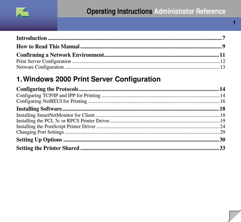
TABLE OF CONTENTS
Safety Information...............................................................................................................................................1
Safety during Operation................................................................................................................................1
Power Cord Precautions................................................................................................................................ 2
Power Supply..................................................................................................................................................2
Netzanschluss (Deutch)................................................................................................................................. 2
Symbols...........................................................................................................................................................3
Trademarks..................................................................................................................................................... 4
1. Installation
Installation Requirements................................................................................................................................. 11
Environment..................................................................................................................................................11
Machine Level..............................................................................................................................................11
Minimum Space Requirements................................................................................................................... 11
Power Requirements.................................................................................................................................... 12
Installation Flow Chart..................................................................................................................................... 13
Machine Installation.........................................................................................................................................14
Setting Customer Expectations....................................................................................................................14
Accessory Check..........................................................................................................................................14
Connector/ Front Panel.............................................................................................................................. 15
Installation Procedure..................................................................................................................................16
Initial Setting.................................................................................................................................................18
Initial Setting for Printer.......................................................................................................................18
Initial Startup........................................................................................................................................18
Test Print............................................................................................................................................... 20
Network Settings................................................................................................................................. 22
General Operations for Servicing.................................................................................................................. 26
Power Interlock Switch................................................................................................................................ 26
Switching Procedure of Power Interlock............................................................................................26
Starting the Print Server............................................................................................................................... 27
Shutting Down or Restarting the Print Server............................................................................................. 28
Shutting Down the Print Server...........................................................................................................28
Restarting the Print Server................................................................................................................... 31
Rebooting the Print Server.................................................................................................................. 32
Canceling the Current Print Job.................................................................................................................. 34
5

Test Print........................................................................................................................................................35
How to Access Consoles (Operation Screen)...........................................................................................38
Overview............................................................................................................................................. 38
Local Console......................................................................................................................................39
Remote Console.................................................................................................................................. 41
Backing up Data/ Restoring Data..............................................................................................................42
Automatic Backup for Configuration Data........................................................................................42
Printing Configuration..................................................................................................................................43
Calibration....................................................................................................................................................45
2. Replacement
Cover Removal.................................................................................................................................................47
Left Cover......................................................................................................................................................47
Right Cover...................................................................................................................................................47
Front Cover...................................................................................................................................................48
Unit Removal.....................................................................................................................................................49
HDD.............................................................................................................................................................. 49
HDD (for Operation System)..............................................................................................................49
HDD (for Data Storage)..................................................................................................................... 50
PSU................................................................................................................................................................52
PIC Board..................................................................................................................................................... 54
Cooling Fans................................................................................................................................................ 57
DIMM........................................................................................................................................................... 59
7SEG Board.................................................................................................................................................60
USB Dongle..................................................................................................................................................61
Motherboard................................................................................................................................................62
Removal Procedure.............................................................................................................................62
Operation Checking after Motherboard Replacement................................................................... 64
Time Setting..........................................................................................................................................64
Procedures for Re-setting Options..................................................................................................... 67
Lithium Battery.............................................................................................................................................. 67
CPU/ CPU Cooling Fan..............................................................................................................................69
CPU/ CPU Cooling Fan (Left)............................................................................................................70
CPU/ CPU Cooling Fan (Right)......................................................................................................... 72
6

DVD Drive.....................................................................................................................................................74
Power Supply SW Board............................................................................................................................ 76
3. Software Maintenance
Software Maintenance.................................................................................................................................... 79
Backing up Data/ Restoring Data.................................................................................................................. 80
Overview...................................................................................................................................................... 80
Backing up Data.......................................................................................................................................... 80
Operation from the Printer Screen..................................................................................................... 80
Operation from the Console Screen on the Print Server..................................................................82
Restoring Data..............................................................................................................................................87
Operation from the Printer Screen..................................................................................................... 87
Operation from the Console Screen on the Print Server..................................................................90
System Software Installation Procedure......................................................................................................... 95
Backing up Data.......................................................................................................................................... 95
Reinstalling the System Software................................................................................................................ 95
Restoring Data..............................................................................................................................................97
Updating System Software..............................................................................................................................98
Update Procedure....................................................................................................................................... 98
Operation from the Printer Screen..................................................................................................... 98
Operation from the Console Screen on the Print Server............................................................... 100
4. Troubleshooting
Overview........................................................................................................................................................105
LED Error Code.............................................................................................................................................. 106
Overview....................................................................................................................................................106
How to Deal with an Error Code............................................................................................................. 106
Diagnostic Code Table............................................................................................................................. 106
How to Identify the Location of CPU/DIMM/HDD Errors........................................................................ 110
How to Identify the Location of CPU/DIMM/HDD Errors....................................................................110
CPU....................................................................................................................................................110
DIMM................................................................................................................................................ 112
HDD................................................................................................................................................... 113
How to Solve When an Error Occurs.......................................................................................................... 115
How to Solve When an Error Occurs......................................................................................................115
7

When the Printer SC Occurs............................................................................................................115
When the Print Server Error Occurs................................................................................................ 115
Service Call (SC) Tables............................................................................................................................... 118
Service Call Conditions.............................................................................................................................118
Service Call (SC911)................................................................................................................................119
Traces..............................................................................................................................................................125
Managing Archived Traces......................................................................................................................125
Operation from the Printer Screen...................................................................................................125
Operation from the Console Screen on the Print Server............................................................... 126
Saving Traces............................................................................................................................................ 130
Operation from the Printer Screen...................................................................................................130
Operation from the Console Screen on the Print Server............................................................... 133
Capturing a Print Job.................................................................................................................................137
Image Trouble................................................................................................................................................143
Cannot Get the Solid BK 100% When Selecting PureBlack/RichBlack.............................................. 143
Troubles That Related to the Optional IPDS................................................................................................ 144
Cannot Exit SP Mode While Establishing a Session with the IPDS Print Server................................... 144
Troubles That Related to External Printing Software................................................................................... 145
Data Cannot Be Sent Properly When Using Prinect...............................................................................145
5. Detailed Section Descriptions
Block Diagram and Functions.......................................................................................................................147
Block Diagram...........................................................................................................................................147
Functions.....................................................................................................................................................147
Network.............................................................................................................................................147
PIC Board.......................................................................................................................................... 148
HDD................................................................................................................................................... 148
Mother Board................................................................................................................................... 148
Digital Display Board....................................................................................................................... 148
USB Dongle.......................................................................................................................................148
DVD Drive..........................................................................................................................................148
USB I/F..............................................................................................................................................149
6. Option
IPDS................................................................................................................................................................ 151
8

Activating the IPDS.................................................................................................................................... 151
Activation Procedure.................................................................................................................................151
Optional Features for IPDS.......................................................................................................................158
How to Reactivate..................................................................................................................................... 162
7. Specifications
Specifications................................................................................................................................................. 163
General Specifications..............................................................................................................................163
9

10

1. Installation
Installation Requirements
Environment
1. Temperature Range:
10°C to 32°C (50°F to 90°F)
2. Humidity Range:
10% to 85% RH
3. Ambient Illumination:
Less than 1,500 lux (do not expose to direct sunlight or strong light)
4. Ambient Dust:
Less than 0.10 mg/m3
5. If the place of installation is air-conditioned or heated, do not place the machine where it will be:
1) Subjected to sudden temperature changes
2) Directly exposed to cool air from an air-conditioner
3) Directly exposed to heat from a heater
6. Do not place the machine where it will be exposed to corrosive gases.
7. Do not install the machine at any location over 3,048 m (10,000 feet) above sea level.
8. Place the controller on a strong and level base.
9. Do not place the machine where it may be subjected to strong vibrations.
10. Do not connect the machine to a power source shared with another electrical appliance.
11. The machine can generate an electromagnetic field, which could interfere with radio or television
reception.
Machine Level
1. Front to back: Within ±5° (0.2") away from level
2. Right to left: Within ±5° (0.2") away from level
Minimum Space Requirements
Place the machine near the power source, providing clearance as shown:
11

1: Rear (200 mm or more)
2: Front (200 mm or more)
1: Printer
2: LCT
You may place the print server [A] on the right side of the large capacity tray or printer as shown in the
illustration.
Power Requirements
• Insert firmly the plug in the outlet.
• Avoid using an outlet extension plug or cord.
• Ground the machine. Avoid using a 3-pronged adapter in a 2-hole ungrounded outlet.
• Use the supplied AC power cord with this product.
• Input voltage level: 100-240V, 4.8A, 50/60 Hz
• Do not put anything on the AC power cord.
1. Installation
12

Installation Flow Chart
First install Pro C7110S/C7110/C7100S/C7100. (Hereinafter referred to as printer)
Then install TotalFlow Print Server R-60A. (Hereinafter referred to as print server)
Recommended installation steps are as follows:
Installation Flow Chart
13

Machine Installation
Setting Customer Expectations
Before installation, the customer should be informed of the following:
• Some nodes on the network may be unavailable for up to one hour.
• Installation process will take about 40 minutes.
• The site administrator should be available during the installation for assistance with network
connectivity issues.
• Equipment downtime and impact on the network can be minimized if the site administrator installs a
network node for the print server and confirms network connection for the print server installation.
• The site administrator should have a networked computer available during the installation. The
appropriate software should already be installed. Documentation for the networked computer and
the network operating software should be available.
• The site administrator should install the user software shipped with the print server (user
documentation is also included) onto the networked PCs and Mac OS computers that will print to
the print server.
• This guide covers hardware installation and service. It provides general information on connecting
the print server to the customer's network. For network setup and configuration information for the
network administrator, refer to the instruction manual “Setup Guide".
Accessory Check
No. Description Q'ty
1 Power Supply Code 1
2 Giga Ether Cable 1
3 Power Interlock USB Cable 1
4 EULA 1
5 Release Note 1
6 Setup Guide 1
7 About the handling of the DVD 1
1. Installation
14

No. Description Q'ty
8 DVD: Operating Instructions 1
Connector/ Front Panel
No. Name No. Name
1 VGA monitor port 10 Main power switch
2 USB port (backup) 11 Power connector
3 USB port (keyboard/mouse) 12 DVD drive
4 USB port (keyboard/mouse) 13 Disc eject button
5Gigabit Ethernet port (print server to
network.) 14 Front USB port
6Gigabit Ethernet port (printer to print
server) 15 Power switch
7 Digital display (7-segment) 16 Power indicator
Machine Installation
15

No. Name No. Name
8 Power interlock switch 17 HDD access indicator
9 USB port for power interlock 18 System error indicator
Installation Procedure
• Use two persons when installing this product. This product is 20 kg or more in weight.
• Turn OFF the print server power switch and printer main power switch, then disconnect the power
cords before following procedure.
1. Connect the interface cable [A] to the Gigabit Ethernet port of the printer. ( ×1)
2. Connect the interface cable which is connected to the printer to the Gigabit Ethernet port
(Right) [A] of the print server. ( ×1)
3. Connect the interface cable which is connected to a network to the Gigabit Ethernet port
(Left) [B] of the print server. ( ×1)
1. Installation
16

• To disconnect the interface cable, remove the I/O cover [A].
4. Connect the power interlock USB cable to the slot on the controller box of the printer.
5. Connect the power interlock USB cable [A] to the USB port for power interlock on the
print server.
• Make sure that the ferrite core is attached firmly on the power interlock USB cable.
6. Set the power interlock switch to the ON position.
Machine Installation
17

7. Connect the power cord [A] to the print server.
8. Plug the power cord of the print server to the outlet.
Initial Setting
Initial Setting for Printer
1. Turn ON the main power switch on the printer.
2. Enter the SP mode.
3. Check the following firmware at SP-7-801-255 (ROM No./ Firmware Version).
• System/Copy Ver. 3.00 or higher
• PowerSaving Sys Ver. 1.24 or higher
• Engine Ver. 1.06 or higher
• Web Support Ver. 1.03 or higher
• OpePanel Ver. 2.02 or higher
4. Set the following SP.
• “7” (Kurofune) at SP5-193-001 (External Controller Info. Setting)
• “1” (invalid) at SP5-895-001 (Application invalidation/Printer) (If it is displayed)
5. Exit the SP mode.
6. Turn OFF the main power switch on the printer.
Initial Startup
The print server has a function to interlock the main power with the printer.
By turning this function on in the print server, the print server’s power goes off when the printer is turned
off.
1. Installation
18
Table of contents
Other Ricoh Print Server manuals
