Ridewell Suspensions RAR-254 Manual

254-Single Point-ISM-06-21-18 Page 1 ENG
Suspension Identication..................................... 2
Suspension System/Axle Serial Tag
Installation ............................................................. 3
Prior to Installation
Suspension Mounting
Troubleshooting - HCV Installation
Maintenance .......................................................... 6
Recommended Service Intervals
Parts Illustration
RAR-254 (Narrow Bushing) Suspension
RAR-254 - (Narrow) Compensator/Trunnion Assembly
RAR-254 - (Wide Bushing) Suspension
RAR-254 - (Wide) Compensator/Trunnion Assembly
Bushing Replacement Kit
Bushing Replacement Procedure
Trunnion Center Bushing – Replacement Procedure
Appendix.............................................................. 14
Torque Specications (Narrow Bushing)
Torque Specications (Wide Bushing)
Axle Alignment
Warranty............................................................... 16
Part No.: 9710125
Doc:
254-SinglePoint-ISM 06-21-18
RAR-254
Air Ride Single Point Suspension
Installation and Service Manual

ENG Page 2 254-Single Point-ISM-06-21-18
Gross Axle WeiGht rAtinG CertifiCAtion is per the finAl stAGe
mAnufACturer or Alterer.
this produCt mAy be Covered under one or more pAtents.
AdditionAl pAtents mAy be pendinG.
for more informAtion on pAtent or suspension/Axle CApACity rAtinG
ContACt rideWell CorporAtion.
www.ridewellcorp.com (800) 641-4122
PART NO:
SERIAL NO:
Figure 1.
The Suspension Serial Tag is located on the left-
hand (driver’s side) suspension hanger.
MODEL: PART NO.
SERIAL NO. CAPACITY TON
Introduction
It’s important that the proper suspension model be
chosen for the application in which it is to be used.
The RAR-254 Single Point Suspension is available for
on-highway and vocational applications. The suspen-
sion ships with an integrated 5” drum brake axle.
Refer to the engineering drawing for detailed infor-
mation on the suspension system components and
operating parameters.
Read through the entire Installation and Service
Manual (ISM) before performing any installation or
maintenance procedures.
Identication Tag
Ridewell suspension systems and axles can be identi-
ed by the Part and Serial Number listed on the serial
identication tags.
Suspension Serial Tag
The Suspension Serial Tag provides information on
the suspension model (Figure 1).
The Part Number (254xxxx) refers to the individual
model of the suspension system.
The nine-digit Serial Number (1xxxxxxxx) refers to
the date and order of manufacture of the suspension.
Please refer to both the part number and serial num-
ber when contacting Ridewell for customer service,
replacement parts and warranty information.
Axle Body - Serial Tag
Ridewell-branded axles will have a tag aached to
the axle tube listing the Part Number (165xxxx) and
Serial Number of the axle body (Figure 2).
Notes and Cautions
All work should be performed by a properly trained
technician using the proper/special tools and safe
work procedures.
The ISM uses two types of service notes to provide
important safety guidelines, prevent equipment dam-
age and make sure that the suspension system oper-
ates correctly. The service notes are dened as:
“NOTE”: Provides additional instructions or
procedures to complete tasks and make sure that
the suspension functions properly.
Indicates a hazardous situation or
unsafe practice that, if not avoided, could result
in equipment damage and serious injury.
SUSPENSION IDENTIFICATION
Figure 2.
Ridewell axles have a serial identication tag listing
the Part Number (165xxxx) and Serial Number of
the axle body.

254-Single Point-ISM-06-21-18 Page 3 ENG
INSTALLATION
Installer Responsibilities
The installer of the suspension has the sole responsi-
bility for proper aachment of the suspension system
to the vehicle chassis.
• The installer is responsible for locating the sus-
pension system on the vehicle to provide the
proper load distribution.
• The installer must verify that vehicle crossmem-
bers are positioned to support the suspension at
the installing location.
• It is the installer’s responsibility to determine that
axle spacing conforms to any applicable federal
and local bridge laws.
• The installer must verify that air reservoir volume
requirements are met after suspension installa-
tion. Consult the vehicle manufacturer or Federal
Motor Vehicle Safety Standards (FMVSS) 121 for
more information.
• The installer must verify there is sucient clear-
ance for proper functioning of the suspension, air
springs, brake chambers, axle and tires.
Prior to Installation
Refer to the engineering drawing to conrm dimen-
sional requirements and the range of ride heights
available.
Installations can vary and procedures should be
adapted for dierent vehicles, as needed.
• The Gross Axle Weight Rating (GAWR) is deter-
mined by the system component with the lowest
load rating. Please consult with tire, wheel, axle
and brake manufacturers before installation to
determine the GAWR.
• If vehicle chassis modications are required, con-
sult with the vehicle manufacturer to ensure that
such changes are permied.
• Welding or altering suspension components
is not permied without the express wrien
permission of Ridewell Suspensions.

ENG Page 4 254-Single Point-ISM-06-21-18
Mounting the suspension to the frame
Refer to the engineering drawing for the range of
available ride heights, torque values, spacing and
clearance requirements of the suspension.
The suspension installer has the nal responsibility
of aaching the suspension to the vehicle frame.
Main pivot fasteners are shipped with minimal
torque applied. It is the installer’s responsibility to
properly torque fasteners after the axle(s) is aligned.
Installation Procedure
Before installation, check to make sure that wires,
hoses or other components will not be aected by
drilling into the frame rail. Check the location for
necessary clearances.
Bolts/nuts for aaching the suspension to the ve-
hicle are supplied by the installer. Grade 8 bolts and
anged lock nuts or lock nuts with hardened washers
are recommended.
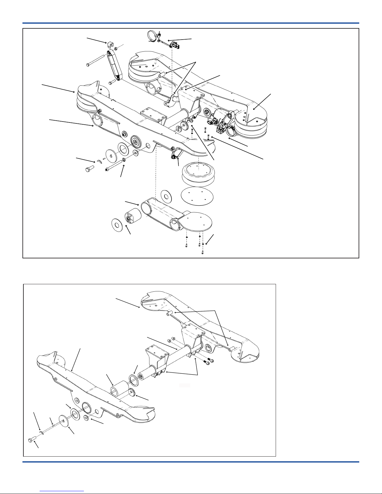
1. Bolt the trunnion hangers to the mounting
brackets or trailer frame. Tighten bolts until
hanger plate is resting on mounting bracket/
trailer frame, but suspension location can still
be adjusted. Do not apply nal torque.
2. Align the trunnion tube with the kingpin. Trun-
nion aligment dimensions “T1” and “T2” shown
on the illustration must be equal (Figure 3).
3. Tighten the trunnion hanger fasteners to speci-
cation. Check trunnion alignment and realign
trunnion tube, if necessary..
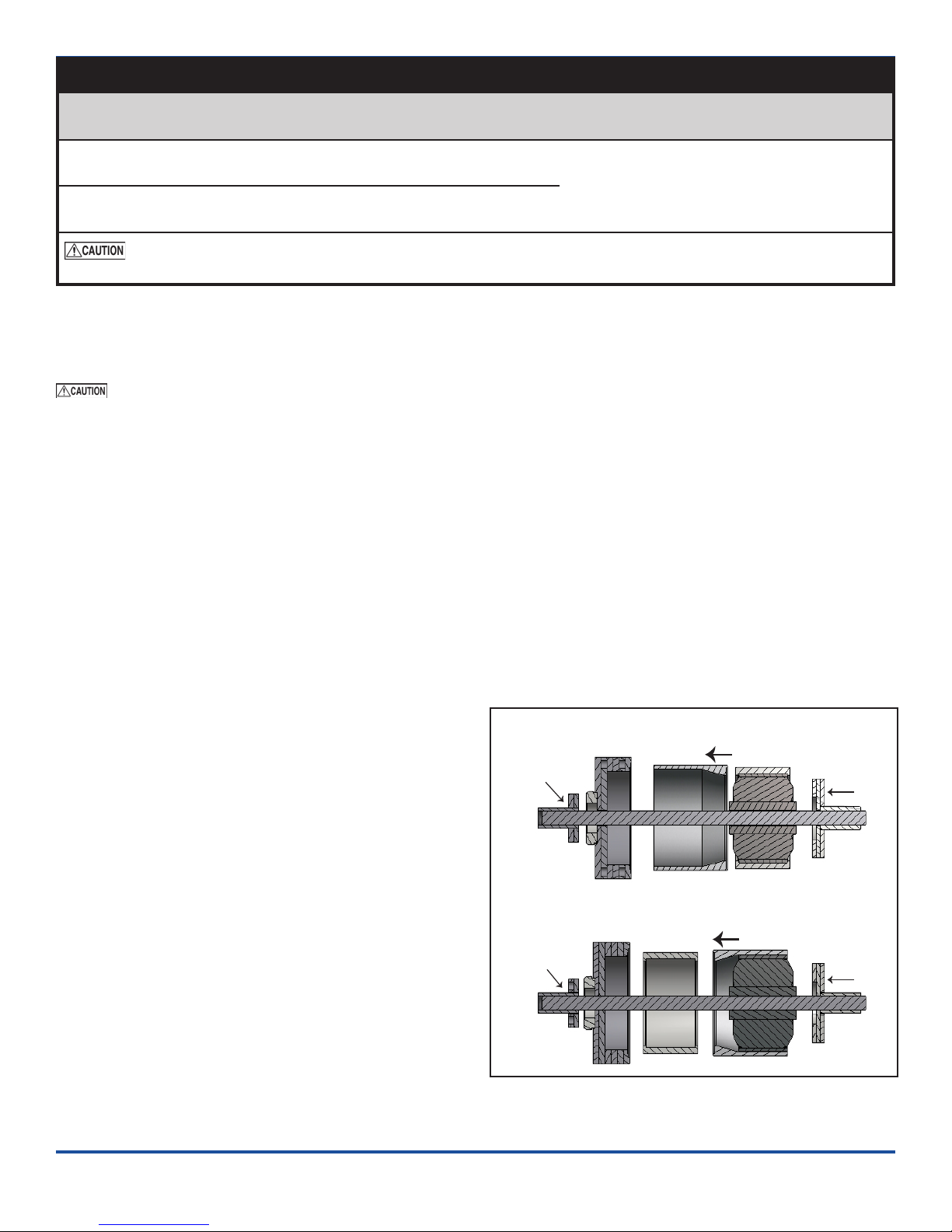
4. Using 1/2”-drive breaker bar, rotate the front axle
beam alignment plate in the opposite direction of
desired axle movement.
Make sure that the alignment plate and align-
ment washer have moved in unison. It is impor-
tant that the pivot bushing is not skewed in the
hanger prior to tightening.
5. Check that axle alignment dimensions “A” and
“B” are equal to +/- 1/8”. Snug the four pivot fas-
teners and recheck alignment (Figure 3).
6. Repeat alignment process on rear axle, ensuring
that rear axle alignment dimensions “C” and “D”
are equal to +/- 1/16”.
7. Check dimension “E”, the lateral centerline rela-
tionship of the trailer body and axles. Dimension
“E” must not exceed 1/4 of an inch.
8. Recheck the alignment of the front axle with the
kingpin. Recheck alignment of the rear axle with
the front axle.
9. After trunnion and axle alignments have been
completed, torque the four pivot bolts using a
1” drive impact wrench and #6100054 E-20 Torx
socket (or equivalent) until the Torx head shears
o from the bolt.
NOTE: Check shear-o. Remove any rough or
jagged fragments so the round pivot bolt head
is completely smooth.
10. Weld the trunnion hanger to the mounting
bracket or trailer frame and frame member with
a 5/16” llet weld.
NOTE: Welding the adjuster plates or the align-
ment washers to the hanger sidewalls is not
required or recommended.
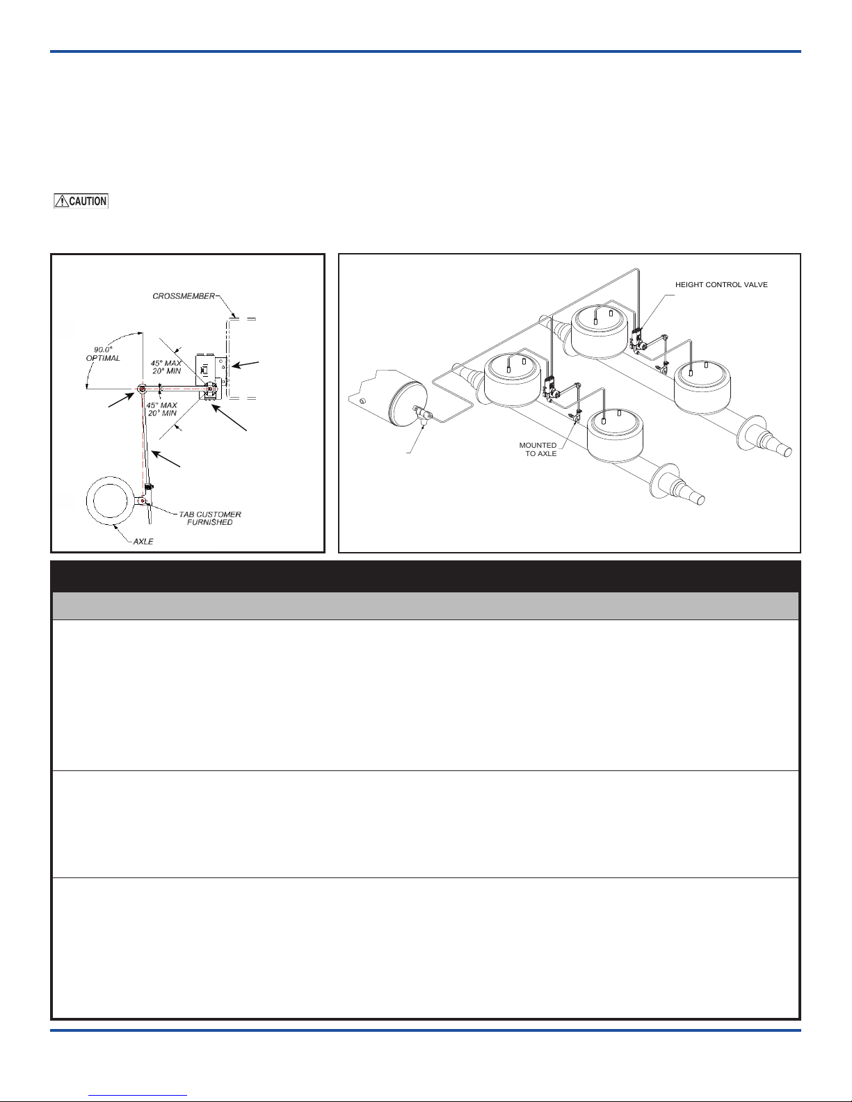
Install/connect the height control kits on the compen-
sator/trunnion assembly. Check the air system tubing
and ings after installation for leaks (Page 5).
Failure to torque bolts/nuts of suspension
components to specications can result in failure of
the suspension and void the warranty.
Welding method must use a minimum weld
tensile strength of 70,000 psi, per AWS specications.
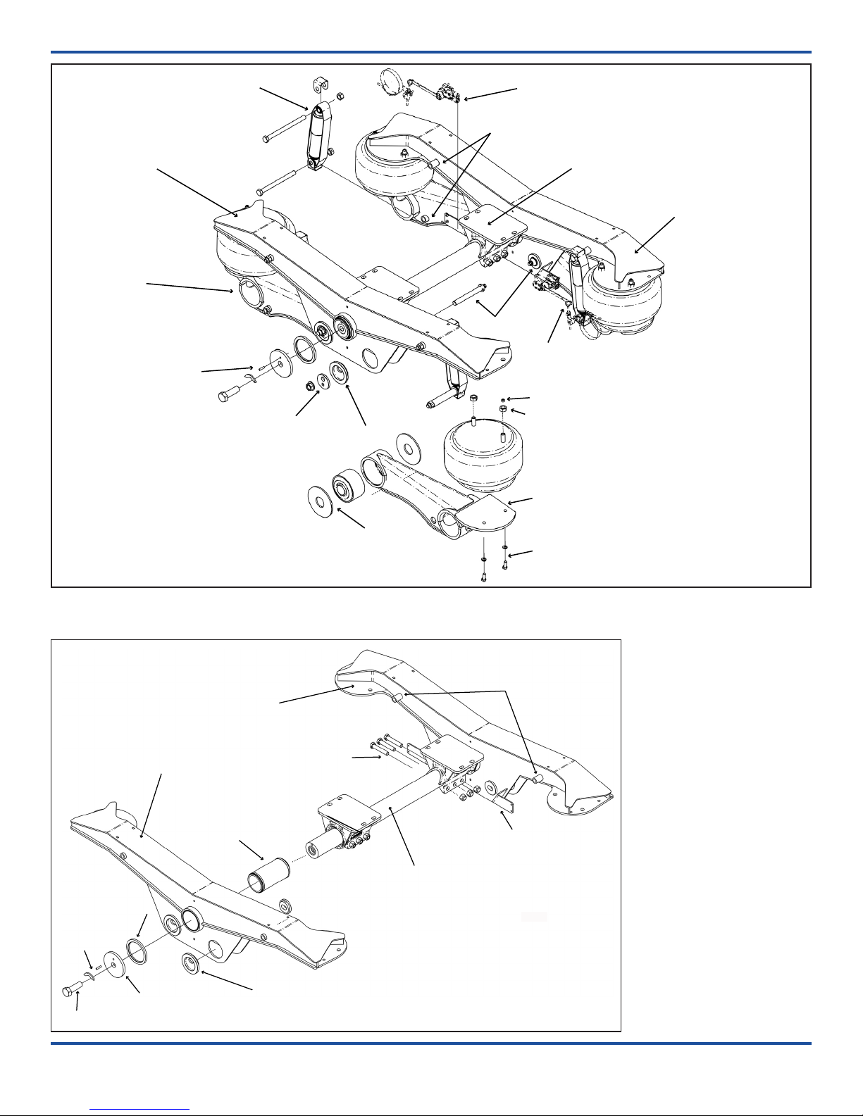
Trunnion Alignment
Axle Alignment
Figure 3.
Measurements for trunnion and axle alignment.
Trunnion Alignment
Axle Alignment

254-Single Point-ISM-06-21-18 Page 5 ENG
Install the height control valves
The Ridewell Extreme Air® Height Control Kit (HCK) assembly drawing 6300AAA00 shows various congu-
rations of the lever arm, height control valve (HCV) and vertical rod arm/ linkage (Figure 4).
RAR-254 Single Point suspensions HCKs are congured by starting with kit 63xxBBAJ00 and replacing the two
“X’s” with the height control and pressure protection valve congurations from the HCK assembly drawing.
Be sure to check the air system after installation for leaks (Figure 5).
The installer is responsible for making sure air system requirements comply with the appropriate
Federal Motor Vehicle Safety Standards.
HEIGHT CONTROL VALVE
MOUNTED TO
TRUNNION/COMPENSATOR
ASSEMBLY
PRESSURE
PROTECTION
VALVE
(REQUIRED)
AIR
TANK
MOUNTED
TO AXLE
Height Control Valve (HCV)
Universal
Mounting
Bracket
Vertical Link
Lever
Arm
Troubleshooting – Height Control Valve Installation
Problem Possible Cause Corrective Action
HCV is
not receiving air/
HCV is not
delivering air
to the air springs.
— Blocked air supply line.
— Air tank is not filling/
reaching set pressure.
— Pressure Protection
Valve (PPV) not working
correctly.
— Pilot port is not
plumbed or is plumbed
incorrectly.
— Verify air lines are pressurized by removing
supply line at HCV. Check for pinched lines.
— Verify air tank pressure with manual/in-line
pressure gauge.
— Check PPV operation by making sure that valve
opens when system reaches the desired pressure
setpoint (usually greater than 70 psi).
— Check HCV configuration – Non-Dump; Pressure-
Dump (Normally Open); Zero-Pressure Dump
(Normally Closed). Reinstall, if necessary.
Air springs ll
but do not exhaust.
— Obstructed air line.
— HCV installed
backwards.
— Supply line installed in
suspension port
— Disconnect linkage and rotate actuating lever
to down position (exhaust). If springs remain
inflated, check for pinched/blocked lines.
— Check installation. Reinstall, if necessary.
— Move air supply line to HCV supply port.
Air system leaks
down in a short
period of time.
— HCV installed
backwards.
— Leak in air system
beyond accepted
standards.
— Disconnect HCV linkage and rotate actuating
lever to the up position (fill). If air springs do
not inflate, reinstall HCV.
— To find leak in the HCV area, pressurize system
and spray soapy water solution onto the valve
and lines. Check for bubbles (leaks):
No leak found – Do not remove valve, check
the rest of the system for leaks.
Check that tubing cuts are straight and smooth.
Re-cut and reassemble if necessary.
Figure 4. HCK installation example
Figure 5. RAR-254 Air Ride Single Point plumbing installation

ENG Page 6 254-Single Point-ISM-06-21-18
MAINTENANCE
A visual inspection of the suspension structure should be performed during each pre-trip/safety inspection.
Ridewell Suspensions recommends the following minimum service intervals for standard duty, on-highway
usage applications. More frequent intervals are recommended for heavier duty applications.
Daily/Pre-Trip Inspections
___ Check tires for proper ination, damage or
excessive wear.
___ Check wheel-ends for obvious signs of lubricant
leakage. Check for missing components.
___ Check
axle assemblies for damage or loose
components.
___ Visually inspect suspension structure for signs
of damage or excessive wear.
___ Check for loose or missing bolts/nuts. Check for
irregular movement in suspension components.
___ Make sure air controls are operating properly.
Drain all moisture from air reservoirs.
First 6,000 miles of use
___ Torque all suspension component bolts/nuts to
specications (Appendix/Engineering drawing).
___ Verify suspension is operating at the installed
ride height.
Every 12,000 miles of use
___Inspect air springs for any damage or excessive
wear. Torque air spring bolts/nuts to specications
(Appendix/Engineering drawing).
___ Check air lines and connections for leaks.
Every 50,000 miles of use
___ Torque all suspension component bolts/nuts to
specications (Appendix/Engineering drawing).
Annually/100,000 miles of use
___ Inspect pivot connection for worn pivot bushing
and wear washers. Replace components, if neces-
sary. Torque suspension component bolts/nuts to
specications (Appendix/Engineering drawing).
___ Check arm beam-to-
axle connection welds.
___ Check lubrication level in wheel ends:
1) Oil-Filled Wheel Ends:
Refill/Replace lubricant as needed (Refer to
TMC RP 631 “100K/Annual Inspection”).
2) Semi-Fluid Grease:
Pull outer bearing and visually inspect
lubrication level. Rell/Replace as needed
(Refer to TMC RP 631 “Level 3 Lubrication Level
Inspection” and TMC RP 618 “Wheel Bearing
Adjustment Procedure”).
___ Check air lines and connections for leaks.
___ Test air control system pressure protection valve
(PPV), if equipped.
___ Check height control valve (HCV) adjustment.
___ Verify that the suspension is operating at the
installed ride height.
Failure to torque the bolts/nuts of suspen-
sion components to specications can result in failure
of the suspension and voiding of the warranty.
Refer to the following Technology &
Maintenance Council (TMC) publications
for additional maintenance information:
TMC RP 609 Self-Adjusting and Manual Brake
Adjuster Removal, Installation
and Maintenance
TMC RP 618 Wheel Bearing
Adjustment Procedure
TMC RP 619 Air System Inspection Procedure
TMC RP 622 Wheel Seal and Bearing Removal,
Installation, and Maintenance
TMC RP 631 Recommendations for
Wheel End Lubrication
TMC RP 643 Air Ride Suspension
Maintenance Guidelines
TMC RP 728 Trailer Axle Maintenance

254-Single Point-ISM-06-21-18 Page 7 ENG
Pivot Bushing (Narrow)
Wear Washers
Pivot Nut
Alignment Plate
Replaceable Pivot (2 pcs)
Axle Beam Pedestal Assembly
(Rear)
Bolt
Lock Washer
(Air Spring)
Pipe Plug
Locknut
(Air Spring)
Mounting Bracket
Shock Strap
Bolt/Locknut
Shock Absorber
Axle Beam
Pedestal Assembly
(Front)
Height Control Kit
Compensator/Trunnion Assembly
(RH/HCV Brackets)
Pivot Bolt
Mounting Point
(Shock Absorber/Shock Strap)
Compensator/Trunnion Assembly
(LH)
Bolt
Locking Plate
Dowel Pin
End Cap
Thrust Washer
Height Control Kit
Shock Absorber Assembly
Trunnion Shaft/Hanger Assembly
Figure 7.
RAR-254 (Narrow)
Compensator/Trunnion
Assembly
Refer to the engineering
drawing for the compo-
nent part number.
Thrust Washer
Compensator/Trunnion Assembly
(LH)
Bolt/Locknut
(Trunnion Hanger)
Mounting Point
(Shock Absorber/Shock Strap)
Compensator/Trunnion Assembly
(RH/HCV Brackets)
Trunnion Hanger/Shaft Assembly
Bolt
Replaceable Pivot
(Two Pieces)
Trunnion Center Bushing
End Cap
(Trunnion Assembly)
Locking Plate
Dowel Pin
Mounting Bracket
(HCV)
Figure 6. RAR-254 Air Ride Single Point Suspension – Narrow Bushing
Refer to the engineering drawing for the component part number.

ENG Page 8 254-Single Point-ISM-06-21-18
Figure 8. RAR-254 Air Ride Single Point Suspension – Wide Bushing
Refer to the engineering drawing for the component part number
Figure 9.
RAR-254 (Wide)
Compensator/Trunnion
Assembly
Refer to the engineering
drawing for the compo-
nent part number
Pivot Bushing (Wide)
Wear Washers
Pivot Bolt
Flat Washer
Replaceable Pivot Boss
Axle Beam Pedestal Assembly
(Rear)
Bolt
Lock Washer
(Air Spring)
Mounting Bracket
Shock Strap
Upper Bolt/Locknut
Lower Bolt
Shock Absorber
Axle Beam
Pedestal Assembly
(Front)
Height Control Kit
Compensator/Trunnion Assembly-RH
(HCV/Shock Mounting Brackets)
Mounting Point
(HCV/Shock Absorber/Shock Strap)
Compensator/
Trunnion Assembly-LH
Bolt
Locking Plate
Dowel Pin
End Cap
Thrust Washer
Height Control Kit
Shock Absorber Assembly
Trunnion Shaft/Hanger Assembly
Pivot Nut
Alignment Plate
Pivot Boss
Bolt
Lock Washer
(Air Spring)
Shock
Assembly
Thrust Washer
Compensator/Trunnion Assembly-LH
Bolt/Locknut
(Trunnion Hanger)
Mounting Point
(Shock Absorber/Shock Strap)
Compensator/Trunnion Assembly - RH
(HCV/Shock Mounting Brackets)
Trunnion Hanger/Shaft Assembly
Bolt
Replaceable Pivot Boss
Trunnion Center Bushing
End Cap
(Trunnion Assembly)
Locking Plate
Dowel Pin
Thrust Washer
Replaceable Pivot Boss

254-Single Point-ISM-06-21-18 Page 9 ENG
Disassemble suspension
Remove wheels and tires. Remove pivot hardware
and alignment plate. Inspect the alignment plate and
repair/replace, as needed. Discard pivot hardware
(new hardware and wear washers are included in the
bushing replacement kit).
Rotate axle beam pedestal assembly down and out
of the trunnion assembly. Inspect the pivot boss for
unusual wear or damage. Repair or replace compo-
nents, as needed.
Narrow Bushing Removal (Tool 6100044)
1. Lubricate the threads of the hex nut-threaded rod
assembly, the inside threads of the plunger, and
the end cap bearing with grease.
2. Assemble the bushing replacement tool and place
on the eye of the beam (Figure 10). NOTE: Cone is
tapered inside to a smaller opening on one end.
2.1 Place the end cap on the hex nut-threaded rod
assembly. The end cap should be seated on the
ange of the hex nut. Place the larger opening
of the cone against the end cap.
2.2 Insert the threaded rod through the bushing
sleeve and center the tapered end of the cone
on the beam eye.
2.3 Thread the plunger onto the threaded rod.
Rotate the plunger until the plate is seated
snugly against the bushing.
3. Use a 3/4” drive impact wrench on the hex nut to
rotate the rod and press bushing out of the beam
eye into the cone. NOTE: A small amount of heat
may be required to break the bond between the
bushing and the beam eye. Do not overheat. Allow
beam to cool before installing the new bushing.
4. Disassemble the bushing replacement tool. Re-
move old bushing from the cone and discard.
New Bushing Installation
1. Use a wire brush to clean any foreign debris and
any corrosion out of the beam eye.
2. Liberally apply P80®lubricant or soap solution
to the inside of the beam eye, the outside of the
replacement bushing and the inside of the cone.
3. The cone is tapered inside to a smaller opening
on one end. Insert the new bushing into the larger
opening of the cone.
Bushing Replacement Procedure
Park the vehicle on a level surface. Chock wheels to keep vehicle from moving. Raise vehicle to height that
removes load from suspension and support with jack stands. Disconnect the linkage from the height control
valve(s), if equipped. Exhaust all air from the air system.
Failure to properly chock wheels, exhaust the air system and safely support the vehicle could allow
vehicle/suspension movement that could result in serious injury.
RAR-254 Air Ride Single Point Suspension – Bushing Replacement Kit
Suspension Type Bushing
REPL Kit Bushing
Install Tool Pivot
Hardware Torque Specication
foot-pound Newton-meter
2540001; 2540003
Narrow Bushing 6040194 6100044 Shear-Type Do not lubricate bolt/nut threads.
Use a 1” drive impact wrench to tighten
pivot bolt until Torx®head is sheared off.
2540004
Wide Bushing 6040098 6100051 Shear-Type
Failure to install and maintain suspension component fasteners at torque specifications could result in
suspension failure and void the warranty. Refer to the engineering drawing for torque values.
Figure 10.
Bushing Replacement Tool 6100044 is for use with
254 narrow bushing suspension models.
Bushing Removal
Bushing Installation
Cone Beam Eye
Beam Eye Cone
End Cap
Hex Nut
Threaded Rod
Assembly Plunger
End Cap
Hex Nut
Threaded Rod
Assembly Plunger
Continued on next page

ENG Page 10 254-Single Point-ISM-06-21-18
4. Assemble the bushing replacement tool and place
on the eye of the beam (Figure 10).
4.1 Place the end cap on the hex nut-threaded
rod assembly. The end cap should rest on the
ange of the hex nut.
4.2 Insert the threaded rod/end cap assembly
through the beam eye. Place the tapered end
of the cone onto the threaded rod and center
the cone on the beam eye.
4.3 Thread the plunger onto the threaded rod.
Rotate the plunger until the plate is seated
snugly against the bushing.
5. Use a 3/4” drive impact wrench on the hex nut to
rotate the threaded rod and press bushing into the
beam eye. NOTE: Hold the plunger with an open
end wrench to prevent the cone from rotating.
6. Disassemble and remove the bushing replacement
tool. Check the placement of the bushing to make
sure it is centered in the beam eye.
Narrow Bushing Replacement Procedure - continued
Figure 11.
Bushing Tool 6100051 is used with
254
wide bushing
suspension models
. The tapered cone allows the
rubber bushing to expand during removal and compresses the bushing for installation.
Bushing Removal
Bushing Installation
Cone Beam Eye
Beam Eye Cone
End Cap
Hex Nut
Threaded Rod
Assembly Plunger
End Cap
Hex Nut
Threaded Rod
Assembly Plunger
Reassemble suspension
Rotate beam assembly into trunnion assembly. Install
pivot connection hardware – alignment washers, ad-
juster plates, wear washers, shear-type pivot bolt, at
washer and anged lock nut.
NOTE: Do not lubricate pivot bolt/nut. Tighten
anged lock nut until adjuster plate pin is engaged
and hardware is snug against hanger. Do not apply
nal torque until axle alignment has been checked.
Connect height control valve linkage, if necessary. In-
ate air springs. Install wheels and tires (if removed).
Raise vehicle and remove support stands. Lower
vehicle to ground.
Check axle alignment and realign (Appendix). Tight-
en pivot bolt with a 1” drive impact wrench and E-20
Torx®socket (Ridewell tool 6100054) until the Torx®
head is sheared o.
Failure to torque the pivot hardware to
specications can result in suspension failure and
void the warranty.
Wide Bushing Replacement Procedure (Tool 6100051)
Disassemble suspension
Remove wheels and tires. Remove pivot hardware
and alignment plate.
Inspect the alignment plate and repair/replace com-
ponents, as needed.
Discard pivot hardware (new hardware and wear
washers are included in the bushing replacement kit).
Rotate the axle beam pedestal assembly down and
out of the trunnion assembly. Inspect the pivot boss
for unusual wear or damage. Repair or replace com-
ponents, as needed.
Bushing Removal
1. Using locator mark on old bushing as a reference,
draw a line on the beam (Figure 12). The line is
used to orient the new bushing during installation.
2. Lubricate threads of threaded rod assembly, inside
the plunger, and the end cap bearing with grease.
Continued on next page

254-Single Point-ISM-06-21-18 Page 11 ENG
Figure 12.
The locator mark on the bushing provides the
correct bushing orientation during installation.
(Wide) Bushing Orientation
Draw Reference Line on Beam
Before Removing Bushing
Locator Mark on Bushing
3. Assemble the bushing replacement tool and place
on the eye of the beam (Figure 11). NOTE: Cone is
tapered inside to smaller opening on one end.
3.1 Place the end cap on the hex nut-threaded rod
assembly. The end cap should be seated on the
ange of the hex nut. Place the larger opening
of the cone against the end cap.
3.2 Insert threaded rod through bushing sleeve
and center tapered end on the beam eye.
3.3 Thread the plunger onto the threaded rod.
Rotate the plunger until the plate is seated
snugly against the bushing.
4. Use a 3/4” drive impact wrench on the hex nut
to rotate the assembly and press the bushing out
of the beam eye into the cone. NOTE: A small
amount of heat may be needed to break the bond
between bushing and beam eye. Do not overheat.
Allow beam to cool before installing new bushing.
5. Disassemble the bushing replacement tool. Re-
move old bushing from the cone and discard.
New Bushing Installation
1. Use a wire brush to clean any foreign debris and
any corrosion out of the beam eye.
2. Coat the inside of the beam eye, the outside of the
bushing and the inside of the cone with S.G. Type
“M” Rubber Assembly Oil. NOTE: Do not substi-
tute (S.G. Type “M” Rubber Assembly Oil included in
bushing replacement kit).
3. The cone is tapered inside to a smaller opening
on one end. Insert the new bushing into the larger
end of the cone with the locator mark of the new
bushing on the outside.
4. Assemble the bushing replacement tool and place
on the eye of the beam (Figure 11).
4.1 Place the end cap on the hex nut-threaded
rod assembly. The end cap should rest on the
ange of the hex nut.
4.2 Insert the threaded rod/end cap assembly
through the beam eye. Place the tapered end
of the cone onto the threaded rod and center
the cone on the beam eye. Line up locator
mark on new bushing with line drawn on
beam during bushing removal (Figure 11).
4.3 Thread the plunger onto the threaded rod.
Rotate the plunger until the plate is seated
snugly against the bushing.
5. Use a 3/4” drive impact wrench on the hex nut to
rotate the threaded rod and press the bushing into
the beam eye. NOTE: Hold plunger with an open
end wrench to prevent the cone from rotating.
6. Disassemble and remove the bushing replacement
tool. Check the placement of the bushing to make
sure it is centered in the beam eye.
Reassemble suspension
Rotate arm beams into trunnion assembly. Install
pivot connection hardware – alignment washers, ad-
juster plates, wear washers, shear-type pivot bolt, at
washer and anged lock nut.
NOTE: Do not lubricate pivot bolt/nut. Tighten
anged lock nut until adjuster plate pin is engaged
and hardware is snug against hanger. Do not apply
nal torque until axle alignment has been checked.
Install shock absorbers. Connect height control valve
linkage (if disconnected) and inate air springs.
Install wheels and tires (if removed). Raise vehicle
and remove support stands. Lower vehicle to ground.
Check axle alignment and realign (Appendix).
Tighten pivot bolt with a 1” drive impact wrench and
E-20 Torx®socket (Ridewell tool 6100054) until the
Torx head is sheared o.
Failure to torque pivot hardware to speci-
cations can result in failure of the suspension and
void the warranty.
Wide Bushing Replacement Procedure - continued

ENG Page 12 254-Single Point-ISM-06-21-18
Trunnion Center Bushing – Replacement Procedure
Park the vehicle on a level surface. Chock wheels to keep vehicle from moving. Raise vehicle to height that
removes load from suspension and support with jack stands. Exhaust all the air from the air system before
disassembling the suspension. Failure to properly chock wheels and exhaust the air system could al-
low vehicle movement that could result in serious injury.
RAR-254 Single Point Suspension – Trunnion Bushing Replacement Hardware
Part No. Assembly Hardware Torque Values
Narrow Bushing Suspension
1143773B105 Trunnion Shaft Bolt (HHCS) 1-1/8”-12NF (Grade 5) 500 ft-lb 678 N-m
1120049 Trunnion Center Bushing
1130048
1150067
Pivot Bolt - Shear-Type
Pivot Nut (Flanged Lock Nut)
Do not lubricate bolt/nut threads. Use a
1” drive impact wrench to tighten pivot
bolt until Torx®head is sheared off.
Wide Bushing Suspension
1143773B105 Trunnion Shaft Bolt (HHCS) 1-1/8”-12NF (Grade 5) 500 ft-lb 678 N-m
1120048 Trunnion Center Bushing
1130031
1150067
Pivot Bolt - Shear-Type
Pivot Nut (Flanged Lock Nut)
Do not lubricate bolt/nut threads. Use a
1” drive impact wrench to tighten pivot
bolt until Torx®head is sheared off.
Failure to install and maintain fasteners at torque specifications could result in suspension failure and
void the warranty. Refer to the engineering drawing for torque values.
Continued on next page
The front and rear axle beam pedestal assemblies
must be removed from the suspension before the
compensator assembly can be removed from the
trunnion hanger/shaft assembly (Fig. 13).
1. Disconnect and remove the air springs. Remove
the shock absorber assemblies.
2. Disconnect and remove the height control valve.
Loosen clamp on P-Connector and remove HCV
and linkage. NOTE: Do not loosen or remove the
axle band clamp.
3. Remove pivot bolts and lower the beam assembly
from the compensator/trunnion assembly.
Do not reuse shear-type pivot bolts.
4. Grind o the weld on the locking plate over the
trunnion shaft bolt. Remove the locking plate,
dowel pin, trunnion shaft bolt, end cap and thrust
washer (Fig. 14-15).
NOTE: Dowel pin required for reassembly.
5. Support compensator/trunnion assembly by
wrapping chains around the assembly as close
to the trunnion shaft as possible. Place a portable
hydraulic power unit between the end of the
trunnion hanger shaft and the chains wrapped
around the compensator assembly.
NOTE: Portable power unit should not press
against internal threaded area of trunnion shaft.
6. Remove compensator/trunnion assembly from
the trunnion hanger/shaft assembly. Press the
center bushing out of the trunnion assembly.
7. Lubricate the trunnion assembly opening with
silicon spray.
Do not use solvent-based lubricants.
Place new bushing so that the end number
(RW60000-narrow; 1120048-wide) faces the center
of the trailer. Press bushing into place, making
sure it is centered in trunnion opening.
Figure 13. Axle beam pedestal assembly removal
Pivot Bushing (Narrow)
Wear Washers
Pivot Nut
Alignment Plate
Replaceable Pivot (2 pcs)
(Rear)
Axle Beam
Pedestal Assembly
(Rear)
Bolt
Lock Washer
(Air Spring)
Pipe Plug
Locknut
(Air Spring)
Axle Beam
Pedestal Assembly
(Front) Pivot Bolt
Compensator/Trunnion Assembly
(LH)
Bolt
Locking Plate
Dowel Pin
End Cap
Thrust Washer
(Trunnion)
Shock Absorber Assembly
Trunnion Shaft/Hanger Assembly

254-Single Point-ISM-06-21-18 Page 13 ENG
Thrust Washer
Compensator/Trunnion Assembly
(LH)
Bolt/Locknut
(Trunnion Hanger)
Mounting Point
(Shock Absorber/Shock Strap)
Compensator/Trunnion Assembly
(RH/HCV Brackets)
Trunnion Hanger/Shaft Assembly
Bolt
Replaceable Pivot
(Two Pieces)
Trunnion Center Bushing
End Cap
(Trunnion Assembly)
Locking Plate
Dowel Pin
Mounting Bracket
(HCV)
Figure 14.
RAR-254 – Narrow Compensator/
Trunnion Assembly Components
(see 6110039/610042 drawing)
8. Manually dress the outside of the shaft of the
trunnion hanger/shaft assembly with emery cloth.
Lubricate the outside of the shaft and inside the
center bushing with silicon spray.
9. Place thrust washer on trunnion hanger/shaft as-
sembly. Install the trunnion assembly.
10. Install thrust washer, end cap, dowel pin and
trunnion shaft bolt on installed trunnion assem-
bly. Torque the shaft bolt to 500 ft-lb.
11. Place locking plate on the shaft bolt head to cover
the dowel pin and weld in place.
Reassemble suspension.
Install axle beam assemblies with one wear washer
on each side of pivot bushing. Torque pivot bolt to
specications (see chart).
Install and reconnect the height control valve and
linkage assemblies.
Install air springs. Install shock absorber assemblies.
NOTE: Check the air system tubing and ings after
installation for leaks.
Replace wheels and tires. Remove jack stands and
lower suspension to ground. Check installed ride
height; adjust if necessary.
Thrust Washer
Compensator/Trunnion Assembly-LH
Bolt/Locknut
(Trunnion Hanger)
Mounting Point
(Shock Absorber/Shock Strap)
Compensator/Trunnion Assembly - RH
(HCV/Shock Mounting Brackets)
Trunnion Hanger/Shaft Assembly
Bolt
Replaceable Pivot Boss
Trunnion Center Bushing
End Cap
(Trunnion Assembly)
Locking Plate
Dowel Pin
Thrust Washer
Replaceable Pivot Boss
Figure 15.
RAR-254 – Wide Compensator/
Trunnion Assembly Components
(see 6110043 drawing)

ENG Page 14 254-Single Point-ISM-06-21-18
APPENDIX
RAR-254 Air Ride Single Point Suspension (Narrow) - Torque Specications
Fastener Type Size Torque Values
foot-pound Newton-meter
Pivot Bolt (Shear-Type)
Pivot Nut (Lock-Nut) 7/8”- 9NC Use a 1” drive impact wrench to tighten pivot bolt
until Torx head is sheared off.
Shock Bolt/Nut 3/4”- 10NC 200-230 ft-lb 271-312 N-m
Air Spring Nut, Upper 3/4”- 16NF 45-50 ft-lb 61-68 N-m
Air Spring Nut, Lower 1/2”- 13NC 45-50 ft-lb 61-68 N-m
Trunnion Bushing Bolt 1 1/8”- 12NC 500 ft-lb 678 N-m
Torque values reflect a lubricated thread condition (Nuts are pre-lubed). Do not overtorque.
Suspension is shipped with minimal torque applied to fasteners. It is the installer’s responsibility
to apply the proper torque values. All fasteners MUST be re-torqued after the first 6,000 miles of operation.
Failure to install and maintain fasteners at torque specifications could result in suspension failure and voiding
of the warranty. Refer to the engineering drawing for torque specifications.
RAR-254 (Wide) - Torque Specications
Fastener Type Size Torque Values
foot-pound Newton-meter
Pivot Bolt (Shear-Type)
Pivot Nut (Lock-Nut) 7/8”- 9NC Use a 1” drive impact wrench to tighten pivot bolt
until Torx head is sheared off.
Shock Bolt/Nut 3/4”- 10NC 200-230 ft-lb 271-312 N-m
Air Spring Bolt/Nut, Upper 3/8”- 16NF 20-25 ft-lb 27-34 N-m
Trunnion Bushing Bolt 1 1/8”- 12NC 500 ft-lb 678 N-m
Torque values reflect a lubricated thread condition (Nuts are pre-lubed). Do not overtorque.
Suspension is shipped with minimal torque applied to fasteners. It is the installer’s responsibility
to apply the proper torque values. All fasteners MUST be re-torqued after the first 6,000 miles of operation.
Failure to install and maintain fasteners at torque specifications could result in suspension failure and voiding
of the warranty. Refer to the engineering drawing for torque specifications.

254-Single Point-ISM-06-21-18 Page 15 ENG
Axle Alignment
Figure 16.
Trunnion and pivot connections hardware
(254-wide bushing version shown)
AXLE ALIGNMENT
"T2"
"T1"
KING PIN
CENTER POINT
"D"
"C"
"B"
"A"
"E"
KING PIN
CENTER POINT
Trunnion Alignment
Axle Alignment
Figure 17. Kingpin measurements for single point suspen-
sion trunnion and axle alignment.
Trunnion Alignment
Axle Alignment
Pivot Bushing (Wide)
Wear Washers
Pivot Bolt
Flat Washer
Replaceable Pivot Boss
Axle Beam Pedestal Assembly
(Rear)
Bolt
Lock Washer
(Air Spring)
Mounting Bracket
Shock Strap
Upper Bolt/Locknut
Lower Bolt
Shock Absorber
Axle Beam
Pedestal Assembly
(Front)
Height Control Kit
Compensator/Trunnion Assembly-RH
(HCV/Shock Mounting Brackets)
Mounting Point
(HCV/Shock Absorber/Shock Strap)
Compensator/
Trunnion Assembly-LH
Bolt
Locking Plate
Dowel Pin
End Cap
Thrust Washer
Height Control Kit
Shock Absorber Assembly
Trunnion Shaft/Hanger Assembly
Pivot Nut
Alignment Plate
Pivot Boss
Bolt
Lock Washer
(Air Spring)
Shock
Assembly
Alignment should be performed on a level
surface with the suspension at the desired
ride height. Front axle alignment shall be in
accordance with SAE or TMC recommended
standards.
1. Loosen pivot nut (Figure 16).
2. Using 1/2” drive breaker bar, rotate front
axle beam alignment plate opposite the
direction of desired axle movement.It is
important that the pivot bushing is not
skewed in the hanger prior to tightening.
3. Measure from the kingpin center point
(Figure 17).Check that dimension “A” and
“B” are equal within +/- 1/8”. Snug pivot
fasteners and recheck alignment.
4. Repeat alignment process on rear axle
ensuring that “C” and “D” dimensions are
equal within +/- 1/16”.
5. Check dimension “E”, the lateral centerline
relationship of the trailer body and axles.
Dimension “E” must not exceed 1/4 of an
inch.
6. Recheck the alignment of the front axle
with the kingpin. Check alignment of the
rear axle with the front axle.
7. Torque all four pivot bolts using a 1” drive
impact wrench and #6100054 E-20 Torx
socket (or equivalent) until the Torx head
shears o from the bolt.
Welding of the alignment plates/washers
to the hanger sidewalls is not required or
recommended.

ENG Page 16 254-Single Point-ISM-06-21-18
WARRANTY
Terms and coverage in this warranty apply only to the United States and Canada.
Ridewell Suspensions warrants the suspension systems manufactured by it to be free of defects in mate-
rial and workmanship. Warranty coverage applies only to suspensions that have been properly installed,
maintained and operated within the rated capacity and recommended application of the suspension. The
responsibility for warranty coverage is limited to the repair/replacement of suspension parts. The liability
for coverage of purchased components is limited to the original warranty coverage extended by the manu-
facturer of the purchased part.
All work under warranty must have prior wrien approval from the Ridewell warranty department. Ride-
well has the sole discretion and authority to approve or deny a claim and authorize the repair or replace-
ment of suspension parts. All parts must be held until the warranty claim is closed.
Parts that need to be returned for warranty evaluation will be issued a Returned Materials Authorization
(RMA). Parts must be returned to Ridewell with the transportation charges prepaid. The transportation
charges will be reimbursed if the warranty claim is approved.
This non-transferable warranty is in lieu of all other expressed or implied warranties or representations,
including any implied warranties of merchantability or tness or any obligations on the part of Ridewell.
Ridewell will not be liable for any business interruptions, loss of profits, personal injury, any costs of
travel delays or for any other special, indirect, incidental or consequential losses, costs or damages.
Contact the Ridewell Warranty Dept. at 417.833.4565 - Ext. 135, for complete warranty information.
Table of contents
Other Ridewell Suspensions Automobile Part manuals
Popular Automobile Part manuals by other brands

Edelbrock
Edelbrock 65732 installation instructions

Edelbrock
Edelbrock 6876 instructions

AEM
AEM 22-483 installation instructions

Edelbrock
Edelbrock Performer 4754 installation instructions

Fisher
Fisher Minute Mount L-Series Service parts

AUTOTECH
AUTOTECH 10.297.400K-402K 410K-412K installation instructions