Ridewell Suspensions Extreme Air Operating and maintenance instructions

Service Notes:
Always wear safety glasses and other required personal protec-
tive equipment when working on the air system. Park vehicle
on a at, level, debris-free surface. Chock the vehicle wheels
to prevent movement. Raise the suspension/axle system to the
desired ride height and support.
Failure to provide proper support, chock vehicle’s
wheels or exhaust the air system could allow vehicle movement
that could result in serious injury.
Height Control Kit (HCK) Installation Procedure
Refer to the vehicle or suspension manufacturers instructions
for mounting position and valve orientation (Figure 5). Inspect
all air line tubing, ings and components for air leaks and
repair before installation.
1. Check location of alignment notch on drive cap, place lever
arm into drive cap slots and aach lever (Figure 2). Torque
screw to 50-55 in-lbs. Make sure lever arm rotates up to ll
(“FILL”) and down to exhaust (“EXH”).
2. Mount the height control valve (HCV) with lever arm to
the vehicle frame or mounting bracket with two T-bolts
(Figure 3). Torque to 60-80 in-lbs.
3. Aach the vertical link “P-Connector” to the lower mount-
ing bracket with lower pin. Torque to 90-120 in-lbs. Make
sure lever arm in the center position, slide vertical link
(rod) up-or-down through P-Connector until grommet is
at the same height as lever arm. Connect vertical linkage to
lever with upper pin. Torque
to
60-80 in-lbs.
4. Slide vertical link up-or-down through the P-Connector
until lever arm reaches desired angle (Figure 3). Tighten the
band clamp on the P-
Connector to hold vertical link in
place. Leave approximately 1” of the rod beneath the “P”
connector and
cut o excess.
5. Install air lines to the HCV supply port and the suspension
and dump ports (Figure 2)
6. Pressurize air system and check for leaks (Figure 6).
7. Remove the suspension/axle system supports. Lower sus-
pension/axle to ground.
Height Control Valve
Kit Installation Guide
1/4” Flanged Nut
1/4”T-Bolt
Supply Port
5/16” or 1/4”
Flanged Nut
Exhaust Valve
Lower Pin
P-Connector
Clamp
Upper Pin
1/4” Flanged Nut
Drive Cap
Grommet
Vertical
Link
Lever
Self-Tapping
Screw
Suspension
Ports
Alignment
Notch
Height Control Valve (HCV)
Universal
Mounting
Bracket
Vertical
Link
Lever
Part No.: 9710008
Doc: HCV-Install-RevJ-09-23-16
Figure 1.
Refer to engineering drawing 63300AAAA00-R for available
height control kits.
Figure 2.
Pressure-Dump (Normally Open), Zero-Pressure Dump (Normally
Closed) and Non-Dump HCV congurations are available.
The Extreme Air™Lo-Flo is available for air control systems that
need a slower reacting, slower owing Height Control Valve.
Figure 3.
HCV-to-lever angles between 20- and 45-degrees provide full
jounce and rebound travel.
8. Move suspension through entire travel range to ensure no
linkage binding, toggling or interference is present at full
jounce and rebound of the suspension system.
Operational Check
Raise the suspension by manually rotating the lever arm 20-30
degrees towards the “FILL” position. Hold lever in place until
air springs inate. Release the lever to exhaust air springs. If
air springs do not inate:
• Verify air supply pressure is sucient to open the pres-
sure protection valve (usually greater than 70 psi).
• Check to make sure that any suspension dump/exhaust
feature is not activated.
• Check to make sure lever is oriented properly. The drive
bearing cap may need to be rotated 180 degrees and the
lever re-positioned.
If air springs are inating properly, manually rotate the lever
arm 20-30 degrees towards the “EXH” (Exhaust) position.
Hold lever in place and check that air is escaping from the
exhaust port.
If steer axle is used, be sure the wheels do not inter-
fere with the HCV and linkage system when turned.
Maintenance
• Drain all moisture from air reservoir at regular intervals.
• Periodically check for pinched/damaged lines or loose
ings on components that could cause an air leak in the
system. Repair any problems found.
• Routinely inspect the HCK system to make sure that the
HCV is maintaining the desired ride height. Adjust the
linkage and re-torque fasteners as necessary.
Pre-Installation Notes
• A pressure protection valve (PPV) must be installed at the
air reservoir, when the reservoir is shared with air brakes.
• The exhaust port (rubber boot end) of the height control
valve (HCV) must be installed at, or below, the horizontal
position.
• All HCV ports use push-to-connect (PTC) ings to con-
nect to 3/8’’ tubing.
• The dump pilot port cannot be plugged in the Pressure-
Dump valve conguration. The pilot port must be
plumbed with at least 6” of air line open to atmosphere at
one end.
• NOTE: The dump pilot port must be plumbed in the
Zero-Pressure Dump conguration. The Zero-Pressure
Dump HCV requires a pressure of 75 psi to operate.
• The installer is responsible for making sure that air system
requirements comply with the Federal Motor Vehicle Safe-
ty Standards (FMVSS) 121 for Air Brake Systems.
Figure 4.
Example of Height Control Valve (HCV) installation on vehicle
frame with linkage attached to the axle.
Ridewell suggests the following Technology &
Maintenance Council (TMC) publications:
TMC RP 619B Air System Inspection Procedure
TMC RP 634A Ride Height Concerns and
Adjustment Procedures for Truck/
Tractor Air Ride Suspensions
Pressure Dump Valve Congurations
(Oset Lever Shown)

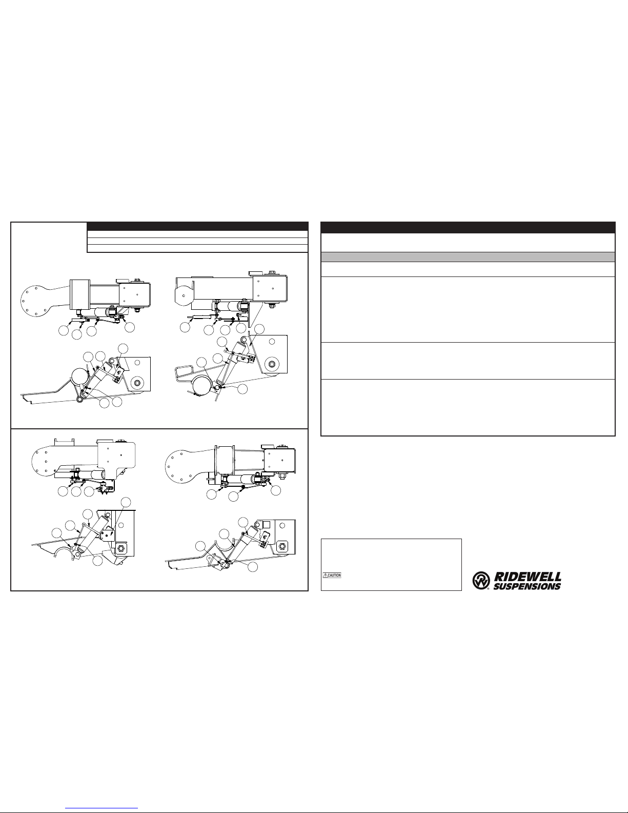
RAR-240 15K, 25K, 30K UNDERSLUNG
RAR-243 25K UNDERSLUNG
RAR-240 25K OVERSLUNG
2
4
7
5
6
2
4
6
5
7
9
3
31
1
8
7
1
3
9
56
42
RAR-260 25K AND 30K UNDERSLUNG
87 3 19
5
6
4
2
RAR-260 25K AND 30K OVERSLUNG
RAR-266 23K AND 25K OVERSLUNG
Figure 6. Troubleshooting Height Control Valve Installation
Height Control Valve - A “bad HCV” is a common misdiagnosis of the air system not working. Most problems can
be traced to other parts of the system. Pinched/damaged lines or loose component fittings are often the cause of an
air leak that causes the HCV to not work as it should. Repair any problems before continuing with troubleshooting.
Problem Possible Cause Corrective Action
Ride Height too high
or too low.
— HCV out of adjustment or
not installed correctly. — Refer to engineering drawing for ride height
specifications. Check adjustment of HCV.
HCV is not
receiving air or is not
delivering air to the
air springs.
— Blocked air supply line.
— Air tank is not filling/
reaching set pressure.
— Pressure Protection Valve
(PPV) not working correctly.
— Pilot port is not plumbed or
is plumbed incorrectly.
— Verify air lines are pressurized by removing
supply line at HCV. Check for pinched lines.
— Verify air tank pressure with manual/in-line
pressure gauge.
— Check PPV operation by making sure that
valve opens when system reaches the desired
pressure setpoint (usually greater than 70 psi).
— Check HCV configuration – Non-Dump;
Pressure-Dump (Normally Open);
Zero-Pressure Dump (Normally Closed).
Reinstall, if necessary.
Air springs ll
but do not exhaust.
— Obstructed air line.
— HCV installed backwards.
— Supply line installed in
suspension port
— Disconnect linkage and rotate actuating lever
to down position (exhaust). If springs remain
inflated, check for pinched/blocked lines.
— Check installation. Reinstall, if necessary.
— Move air supply line to HCV supply port.
Air system leaks
down in a short
period of time.
— HCV installed backwards.
— Leak in air system beyond
accepted standards.
— Disconnect HCV linkage and rotate actuating
lever to the up position (fill). If air springs do
not inflate, reinstall HCV.
— To find leak in the HCV area, pressurize
system and spray soapy water solution onto
the valve and lines. Check for bubbles (leaks):
No leak found – Do not remove valve, check
the rest of the system for leaks.
Check that tubing cuts are straight and
smooth. Re-cut and reassemble if necessary.
Warranty
The Ridewell Corporation warrants the Automatic Height and
Leveling Air Control Valve manufactured by it to be free from
defects in material and workmanship for a period of 1 year
from the date code molded into the body.
Warranty coverage is limited to the repair/replacement of valve
parts. Coverage applies only to valves that have been properly
installed, maintained and operated. No warranty applies to air
lines, ings, mounting hardware, actuating arm, linkage, or
axle aachments.
Ridewell reserves the right to require any valve to be returned
for inspection before claim is obtained. All returns must have
No.Description No.Description No.Description
1Height Control Valve 4Vertical Link 7Lower Pin Assembly
2Lever 5“P” Connector 8Lower Mounting Bracket
3Upper Pin Assembly 6Clamp 9Upper Mounting Bracket
transportation charges prepaid by the customer and accompa-
nied with a complete wrien explanation of claimed defects and
the circumstances of operational failure.
This non-transferable warranty is in lieu of all other expressed
or implied warranties or representations, including any implied
warranties of merchantability or tness or any obligations on
the part of Ridewell.
Ridewell will not be liable for any business interruptions, loss
of prots, personal injury, any costs of travel delays or for any
other special, indirect, incidental or consequential losses, costs
or damages caused by Ridewell.
Figure 5.
EXAMPLES: Common
Height Control Kit (HCK)
installations.
Notes and Cautions
This instruction uses two types of service notes:
“NOTE”: Provides additional instructions or procedures
to complete work tasks and make sure that the component
functions properly.
Indicates a hazardous situation or unsafe practice
that, if not avoided, could result in equipment damage
and serious injury.
Springeld, MO USA
800-641-4122
www.ridewellcorp.com
Popular Control Unit manuals by other brands

Bray
Bray TRI LOK Installation, operation & maintenance manual

Tisch Environmental
Tisch Environmental PUF+ Operator's manual

Danfoss
Danfoss VLT HVAC Drive FC 102 operating instructions

Siemens
Siemens SINAMICS G120 operating instructions

GF
GF JRGUMAT troubleshooting guide

Telit Wireless Solutions
Telit Wireless Solutions GC864 Series Hardware user's guide