Ridge 700 Power drive User manual

RIDGE TOOL COMPANY
Tools For The ProfessionalTM
700
P. 1
P. 13
P. 27
P. 43
P. 59
P. 75
P. 91
P. 107
P. 121
P. 135
P. 149
P. 163
P. 179
P. 195
P. 209
P. 225
P. 241
P. 257
P. 271
P. 285
P. 299
P. 315
P. 329
EN
FR
ES
DE
NL
IT
PT
SV
DA
NO
FI
PL
CZ
SK
RO
HU
EL
HR
SL
SR
RU
TR
KK
www.GlobalTestSupply.com
Find Quality Products Online at: sales@GlobalTestSupply.com

ii
700 P wer Drive
Table of Contents
Recording Form For achine Serial Number..................................................................................................................................1
Safety Symbols ..................................................................................................................................................................................2
General Power Tool Safety Warnings
Work Area Safety ............................................................................................................................................................................2
Electrical Safety ..............................................................................................................................................................................2
Personal Safety ..............................................................................................................................................................................3
Power Tool Use And Care ..............................................................................................................................................................3
Service ............................................................................................................................................................................................3
Specific Safety Information
Power Drive Safety Warnings ........................................................................................................................................................3
Description, Specifications And Standard Equipment
Description ......................................................................................................................................................................................4
Specifications ..................................................................................................................................................................................4
Standard Equipment ......................................................................................................................................................................5
Pre-Operation Inspection ..................................................................................................................................................................5
Set-Up and Operation ........................................................................................................................................................................6
Installing Die Heads ........................................................................................................................................................................6
Resisting Threading Forces ............................................................................................................................................................7
Threading ........................................................................................................................................................................................8
Inspecting Threads..........................................................................................................................................................................9
700 Power Drive – Other Uses ..........................................................................................................................................................9
aintenance Instructions
Cleaning ........................................................................................................................................................................................10
Lubrication ....................................................................................................................................................................................10
Changing Dies in 12-R Die Heads ................................................................................................................................................10
Replacing Brushes in Motor ..........................................................................................................................................................10
Optional Equipment ........................................................................................................................................................................11
achine Storage ..............................................................................................................................................................................11
Service And Repair ..........................................................................................................................................................................11
Thread Cutting Oil Information ......................................................................................................................................................11
Disposal ............................................................................................................................................................................................11
Troubleshooting ..............................................................................................................................................................................12
Lifetime Warranty ..............................................................................................................................................................Back Cover
*Original Instructions - English
www.GlobalTestSupply.com
Find Quality Products Online at: sales@GlobalTestSupply.com

700 P wer Drive
Record Serial Num er elow and retain product serial num er which is located on name plate.
Serial
No.
700
Power Drive
WARNING!
Read this Operat r’s Manual
carefully bef re using this
t l. Failure t understand
and f ll w the c ntents f
this manual may result in
electrical sh ck, re and/ r
seri us pers nal injury.
www.GlobalTestSupply.com
Find Quality Products Online at: sales@GlobalTestSupply.com

This symbol indicates the risk of fingers, hands, clothes
and other objects catching on or between gears or other
rotating parts and causing crushing injuries.
2
700 P wer Drive
General Power Tool afety
Warnings*
WARNING
Read and understand all instructions. Failure to fol-
low all instructions listed below may result in
electric shock, fire, and/or serious injury.
AVE ALL WARNING AND IN TRUCTION
FOR FUTURE REFERENCE!
The term "power tool" in the warnings refers to your
mains-operated (corded) power tool or battery-operated
(cordless) power tool.
Work Area afety
•Keep work area clean and well lit. Cluttered or dark
areas invite accidents.
•Do not operate power tools in explosive atmo-
spheres, such as in the presence of flammable
liquids, gases, or dust. Power tools create sparks
which may ignite the dust or fumes.
•Keep children and by-standers away while operat-
ing a power tool. Distractions can cause you to lose
control.
Electrical afety
•Power tool plugs must match the outlet. Never
mod ify the plug in any way. Do not use any
adapter plugs with earthed (grounded) power
tools. Grounded tools must be plugged into an
outlet properly installed and grounded in accor-
dance with all codes and ordinances. Never
remove the grounding prong or modify the plug in
any way. Check with a qualified electrician if you
are in doubt as to whether the outlet is properly
grounded. Unmodi fied plugs and matching outlets
will reduce risk of electric shock.
•Avoid body contact with earthed or grounded sur-
faces such as pipes, radiators, ranges and refrig-
erators. There is an increased risk of electrical shock
if your body is earthed or grounded.
•Do not expose power tools to rain or wet condi-
tions. Water entering a power tool will increase the risk
of electrical shock.
•Do not abuse the cord. Never use the cord to
carry the tool or pull the plug from an outlet. Keep
cord away from heat, oil, sharp edges or moving
parts. Replace damaged cords immediately.
Damaged cords increase the risk of electric shock.
afety ymbols
In this operator’s manual and on the product, safety symbols and signal words are used to communicate important safe-
ty information. This section is provided to improve understanding of these signal words and symbols.
This is the safety alert symbol. It is used to alert you to potential personal injury hazards. Obey all safety messages that follow this
symbol to avoid possible injury or death.
DAN ER indicates a hazardous situation which, if not avoided, will result in death or serious injury.
WARNIN indicates a hazardous situation which, if not avoided, could result in death or serious injury.
CAUTION indicates a hazardous situation which, if not avoided, could result in minor or moderate injury.
NOTICE indicates information that relates to the protection of property.
This symbol means read the operator’s manual careful-
ly before using the equipment. The operator’s manual
contains important information on the safe and proper
operation of the equipment.
This symbol means always wear safety glasses with
side shields or goggles when handling or using this
equipment to reduce the risk of eye injury.
NOTICE
DANGER
WARNING
CAUTION
This symbol indicates the risk of electrical shock.
This symbol indicates the risk of machine tipping,
causing striking or crushing injuries.
This symbol means do not wear gloves while operat-
ing this machine to reduce the risk of entanglement.
This symbol means always use support device to
help resist threading force, improve control and reduce
the risk of injury.
* The text used in the eneral Power Tool Safety Warnings section of this manual is verbatim, as required, from the applicable UL/CSA 62841-1 edition stan-
dard. This section contains general safety practices for many different types of power tools. Not every precaution applies to every tool, and some do not apply
to this tool.
www.GlobalTestSupply.com
Find Quality Products Online at: sales@GlobalTestSupply.com

3
•When operating a power tool outside, use an out-
door extension cord marked “W-A” or “W”. These
cords are rated for outdoor use and reduce the risk of
electric shock.
•If operating a power tool in a damp location is
unavoidable, use a ground fault circuit interrupter
(GFCI) protected supply. Use of a FCI reduces
the risk of electric shock.
Personal afety
•Stay alert, watch what you are doing and use com-
mon sense when operating a power tool. Do not
use a power tool while you are tired or under the
influence of drugs, alcohol, or medication. A mo -
ment of inattention while operating power tools may
result in serious personal injury.
•Use personal protective equipment. Always wear
eye protection. Protective equipment such as dust
mask, non-skid safety shoes, hard hat, or hearing
protection used for appropriate conditions will reduce
personal injuries.
•Prevent unintentional starting. Ensure the switch
is in the OFF position before connecting to power
source and/or battery pack, picking up or carrying
the tool. Carrying power tools with your finger on the
switch or energizing power tools that have the switch
ON invites accidents.
•Remove any adjusting key or wrench before turn-
ing the power tool ON. A wrench or a key left attached
to a rotating part of the power tool may result in per-
sonal injury.
•Do not overreach. Keep proper footing and bal-
ance at all times. This enables better control of the
power tool in unexpected situations.
•Dress properly. Do not wear loose clothing or
jewelry. Keep your hair, and clothing away from
moving parts. Loose clothes, jewelry, or long hair
can be caught in moving parts.
•If devices are provided for the connection of dust
extraction and collection facilities, ensure these are
connected and properly used. Use of dust collection
can reduce dust-related hazards.
Power Tool Use and Care
•Do not force power tool. Use the correct power tool
for your application. The correct power tool will do the
job better and safer at the rate for which it is designed.
•Do not use power tool if the switch does not turn it
ON and OFF. Any power tool that cannot be con-
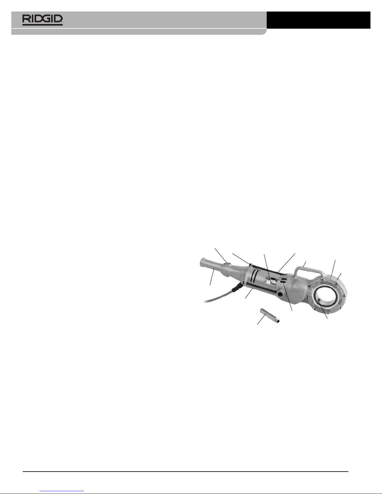
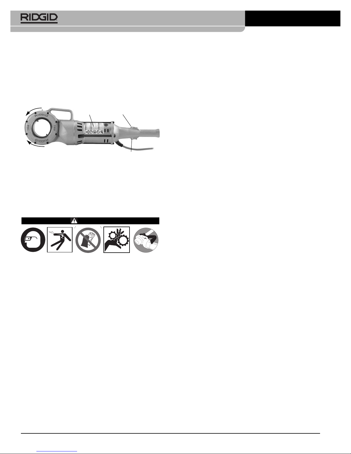
700 P wer Drive
trolled with the switch is dangerous and must be
repaired.
•Disconnect the plug from the power source and/or
the battery pack from the power tool before making
any adjustments, changing accessories, or storing
power tools. Such preventive safety measures reduce
the risk of starting the power tool accidentally.
•Store idle power tools out of the reach of children
and do not allow persons unfamiliar with the power
tool or these instructions to operate the tool. Power
tools are dangerous in the hands of untrained users.
•aintain power tools. Check for misalignment or
binding of moving parts, breakage of parts and any
other condition that may affect the power tool’s op -
er ation. If damaged, have the power tool repaired
before use. Many accidents are caused by poorly
maintained power tools.
•Keep cutting tools sharp and clean. Properly main-
tained cutting tools with sharp cutting edges are less
likely to bind and are easier to control.
•Use the power tool, accessories and tool bits etc. in
accordance with these instructions, taking into
account the working conditions and the work to be
performed. The use of the power tool for operations dif-
ferent from those intended could result in a hazardous
situation.
ervice
•Have your power tool serviced by a qualified repair
person using only identical replacement parts.
This will ensure that the safety of the power tool is
maintained.
pecific afety Information
WARNING
This section contains important safety information
that is specific to this tool.
Read these precautions carefully before using the
700 Power Drive to reduce the risk of electrical
shock,striking, crushing or other serious injury.
AVE ALL WARNING AND IN TRUCTION
FOR FUTURE REFERENCE!
Keep this manual with machine for use by the operator.
Power Drive afety
•Follow instructions on proper use of this machine.
Read and understand the instructions and warn-
ings for all equipment and material being used
www.GlobalTestSupply.com
Find Quality Products Online at: sales@GlobalTestSupply.com

– Contact your local RID ID®distributor.
Description, pecifications
And tandard Equipment
Description
The RID ID®Model 700 Power Drive is designed to pro-
vide power for threading pipe and conduit. Forward and
Reverse rotation can be selected with a reversible switch.
The power drive is designed to use RID ID 12-R Die
Heads (1/8"– 2"pipe). Other RID ID die heads such
as the OO-R and 11-R can be used with adapters.
When threading 1" or larger pipe, a support device, such as
the No. 775 Support Arm or a RID ID 14" heavy duty pipe
wrench is required to resist the threading forces.
The power drive can also be used to power the RID ID 258
Pipe Cutter and for other applications, (See “Ot er Uses”).
Figure 1 – odel 700 Power Drive
pecications
Threading Capacity ....Pipe 1/8" to 2" (3 to 50 mm)
Bolt 1/4" to 1" (6 to 25 mm) with
00-RB Die Head
Motor:
Type .........................Universal, Reversible
Horsepower..............1/2HP
Volts .........................115 V, 50/60 Hz; 230 V, 50/60 Hz
Operating Speed........26-30 RPM, No load
Controls......................Double-Throw Reversible
Switch with spring return to OFF
position
before operating the power drive. Failure to follow
all warnings and instructions may result in property dam-
age and/or serious injury.
•When threading 1" (25mm) or larger pipe, use
support device to resist threading forces. Use an
appropriate support device per these instructions.
Support devices improve control and reduce the risk of
striking, crushing, and/or other injuries.
•When using a support device other than the sup-
port arm, the support device must react against the
motor housing. Support devices contacting other
parts may damage the machine parts or increase the
risk of injury.
•Always firmly hold the power drive when threading
or backing die head off the pipe to resist threading
forces, regardless of support device use. This will
reduce the risk of striking, crushing and other injuries.
•Do not use this power drive if switch button is
broken. This switch is a safety device that lets you shut
off the motor by releasing the switch.
•Do not wear gloves or loose clothing when oper-
ating machines. Keep sleeves and jackets but-
toned. Do not reach across the machine or pipe.
Clothing can be caught by the pipe or machine result-
ing in entanglement.
•One person must control the work process and
machine operation. Only the operator should be in the
work area when the machine is running. This helps
reduce the risk of injury.
•Do not use dull or damaged dies. Sharp cutting
tools require less torque and the power drive is easier
to control.
•Keep handles dry and clean, free from oil and
grease. Allows for better control of tool..
•Keep floors dry and free of slippery materials
such as oil. Slippery floors invite accidents.
•Only use RIDGID die heads with RIDGID 700 Power
Drive, other die heads may not fit correctly in the
power drive increasing the risk of equipment dam-
age and personal injury.
•When using for applications other than described
in this manual, use a support device to resist han-
dle forces. Support devices improve control and reduce
the risk of striking, crushing, and/or other injuries.
The EC Declaration of Conformity (890-011-320.10) will ac -
company this manual as a separate booklet when required.
If you have any question concerning this RID ID®product:
4
700 P wer Drive
Handle
Brush Cap
Fan
Housing
Torque
Arm
Adapter
Pawl
Gear
Case
Handle
Serial Number
Plate
otor
Housing
Switch
Button Warning Label
(on otor Housing) Grease
Fitting
www.GlobalTestSupply.com
Find Quality Products Online at: sales@GlobalTestSupply.com

ear Head .................Die Cast Aluminum, Spur ear
Reduction Face ear Drive,
Spring-Loaded Adapter Pawls,
Hardened Steel Spindle ear
Dimension:
Length......................28¼" (717 mm)
Width........................61/16" (154 mm)
Height.......................713/16" (198 mm)
Weight .......................25 lbs. (11 kg)
tandard Equipment
The Model 700 Power Drive comes with the following
items:
• 700 Power Drive
• Torque arm
• Operator’s Manual
The 700 Power Drive machine serial number plate is
located on the bottom of motor housing. The last 4 digits
indicate the month and year of the manufacture. (12 =
month, 15 = year).
Figure 2 – achine Serial Number
Selection of appropriate materials and instal-
lation, joining and forming methods is the responsibility of
the system designer and/or installer. Selection of improp-
er materials and methods could cause system failure.
Stainless steel and other corrosion resistant materials
can be contaminated during installation, joining and form-
ing. This contamination could cause corrosion and pre-
mature failure. Careful evaluation of materials and methods
for the specific service conditions, including chemical and
temperature, should be completed before any installation
is attempted.
Pre-Operation Inspection
WARNING
Before each use, inspect your
700 Power Drive and correct
any problems to reduce the risk
of serious injury from electric
shock, crushing injuries and
other causes and prevent power drive damage.
1. Make sure that the power drive is unplugged.
2. Clean any oil, grease or dirt from the power drive and
support device, including the handles and controls.
This aids inspection and helps prevent the machine
or control from slipping from your grip.
3. Inspect the power drive for the following:
• Damage or modification to the cord and plug.
• Proper assembly, maintenance and completeness.
• Damaged, misaligned or binding parts.
• Proper operation of switch. Confirm that it cycles
smoothly and does not stick.
• Presence and readability of warning labels (Fi gure
3).
• Any other condition which may prevent safe and
normal operation.
If any problems are found, do not use the power
drive or support device until the problems have been
repaired.
4. Inspect support arm. Make sure gripping teeth are
clean and in good condition. Teeth can be cleaned
with a wire brush.
5. Inspect the cutting edges of the dies for wear, defor-
mation, chips or other issues. Dull or damaged cutting
tools increase the amount of force required, produce
poor quality threads and increase the risk of injury.
6. Inspect and maintain any other equipment being
used per its instructions to make it is sure functioning
properly.
7. Following the Set-Up and Operation instructions,
check the power drive for proper operation.
• Depress and release the switch for FORWARD
rotation and repeat for REVERSE rotation as shown
in Figure 3. Confirm that the power drive rotates as
shown in Figure 3 and that the switch controls the
machine operation.
Allow the power drive to come to a complete stop
before reversing the direction with the switch button.
This will reduce the risk of power drive damage.
5
700 P wer Drive
NOTICE
www.GlobalTestSupply.com
Find Quality Products Online at: sales@GlobalTestSupply.com

• Depress and hold the switch button. Inspect the
moving parts for misalignment, binding, odd noises
or any other unusual conditions. Release the switch.
If the machine does not operate correctly or any
unusual conditions are found, do not use the machine
until it has been repaired.
Figure 3 – Switch Position for Rotational Direction
8. Release the switch button and with dry hands unplug
the machine.
et-Up and Operation
WARNING
et up and operate the 700 Power Drive according
to these procedures to reduce the risk of injury
from electric shock, entanglement, striking, crush-
ing and other causes, and to help prevent power
drive damage.
When threading 1" (25mm) or larger pipe, use sup-
port device to resist threading forces. Use an appro-
priate support device per these instructions. upport
devices improve control and reduce the risk of strik-
ing, crushing, and/or other injuries.
Always firmly hold the power drive when threading
or backing die head off the pipe to resist threading
forces, regardless of support device use. This will
reduce the risk of striking, crushing and other
injuries.
Properly support pipe. This will reduce the risk of
falling pipe, tipping and serious injury.
Do not use a power drive without a properly oper-
ating switch button.
Do not wear gloves or loose clothing when oper-
ating machines. Keep sleeves and jackets but-
toned. Do not reach across the machine or pipe.
Clothing can be caught by the pipe or machine
resulting in entanglement.
One person must control both the work process
and the switch button. Do not operate with more
than one person. In case of entanglement, the oper-
ator must be in control of the switch.
1. Check work area for:
• Adequate lighting.
• Flammable liquids, vapors or dust that may ignite.
If present, do not work in area until sources have
been identified and corrected. The power drives are
not explosion proof and can cause sparks.
• Clear, level, stable, dry location for all equipment
and operator.
• ood ventilation. Do not use extensively in small,
enclosed areas.
• Properly wired electrical outlet of the correct voltage.
If in doubt, have outlet inspected by a licensed
electrician.
• Clear path to electrical outlet that does not contain
any potential sources of damage for the power
cord.
2. Inspect the pipe to be threaded and associated fittings
and confirm that the 700 Power Drive is a correct tool
for the job. See Specifications.
3. Make sure equipment to be used has been properly
inspected.
4. Properly prepare the pipe as needed. Make sure the
pipe is squarely cut and deburred. Pipe cut at an
angle can damage the dies while threading or cause
difficulty engaging the die head.
5. Make sure that pipe to be threaded is stable and
secured to prevent tipping during use. Use appropri-
ate pipe stands to support pipe length.
6. Check the level of RID ID Thread Cutting Oil in the
RID ID 418 oiler. Remove the chip tray and confirm
that the filter screen is clean and fully submerged in
oil. Replace or add oil if necessary. Place the 418
Oiler bucket under the pipe end to be threaded.
Installing Die Heads
1. Make sure the power drive is unplugged from the out-
let.
2. Push 12-R Die Head or Adapter (see Optional Equip -
ment), spline end first, squarely into the Power Drive
until the spring-loaded drive pawls securely engage
the spline. (Figure 4). The die head or adapter can be
inserted into either side of the power drive. In some
6
700 P wer Drive
Forward
Switch
Actuation
Forward Rotation Reverse
Switch
Actuation
Reverse Rotation Warning
Label
www.GlobalTestSupply.com
Find Quality Products Online at: sales@GlobalTestSupply.com

7
Figure 5 – Support Arm Aligned with End of Pipe
Figure 6 – Support Arm Positioned With 700 Power
Drive Slightly Above Horizontal
Using a RIDGID 12", 14" or 18" Heavy Duty Pipe
Wrench:
1. Securely install the torque arm into the fan housing of
the 700 Power Drive. A 5" (127 mm) long piece of ½"
schedule 80 steel pipe with a ½" NPT thread can also
be used.
2. Place the RID ID 12", 14" or 18" Heavy Duty Pipe
Wrench approximately 7" (175 mm) from the end of
the pipe (see Figure 7). Test to confirm the wrench is
secure, and will not fall or move.
3. When starting the thread, the torque arm will sit on the
pipe wrench handle.
Figure 7 – Threading Using Pipe Wrench as a Support
Arm
cases, die heads/adapters may need to be rotated to
allow the pawl to engage. 770 and 773 adapters
must have the die head installed in the adapter prior
to insertion in the Power Drive.
3. To remove, squarely pull die head from power drive. If
needed, use a soft face hammer or a block of wood to
tap the die head out. Do not pound on the die head,
this can damage the tool.
Figure 4 – Installing Die Heads into 700 Power Drive
Resisting Threading Forces
( upport Devices)
For right hand threads, die head will rotate clockwise
(looking at the face of the Die Head). Forces developed by
the threading torque will be in the opposite or counter-clock-
wise direction. Rotation and force will be reversed for left
hand threads. Make sure that the support device is set up
to absorb and resist the threading force.
Using the No. 775 Support Arm:
1. Support arm yoke hook can be assembled to either
side. Securely tighten hinge bolt.
2. Position the support arm on pipe so end of support
arm aligns with end of pipe and 700 Power Drive
will be slightly above horizontal (Figure 5 and 6).
This properly places the support arm for threading and
prevents threading oil from running down power drive.
3. Make sure that the support arm jaws are squarely
aligned with the pipe and securely tighten the support
arm.
700 P wer Drive
Torque Arm
Wrench
www.GlobalTestSupply.com
Find Quality Products Online at: sales@GlobalTestSupply.com

8
700 P wer Drive
Other Support ethods:
Place the power drive motor housing (see Figure 1) a gainst
an adjacent structural member (examples include walls,
beams and joists). This requires that the pipe being thread-
ed and surroundings are able to withstand the weight of the
tool and the threading forces. It may be necessary to add
temporary or permanent pipe supports or structural ele-
ments to properly resist threading forces.
For pipe ¾" diameter and smaller:
Pipe ¾" and smaller nominal dimension can be threaded
without the use of support device. In this case, the operator
resists the threading forces. The pipe must be properly
secured to prevent rotation. Always firmly hold the power
drive when threading or backing die head off pipe to resist
forces. This will reduce the risk of striking, crushing and
other injuries.
Threading
1. With dry hands, plug in the power drive.
2. Position the die head over the pipe end and support
the power drive as directed in the Resisting Threading
Forces Section. Always keep the power drive against
the support device. Do not put anything between the
power drive and the support device – this increases
the risk of pinching and crushing injuries.
3. Assume a proper operating position to help maintain
control of the machine (See Figure 9),
• Be sure you have good balance and do not have to
overreach.
• Be sure you can control the switch button and
machine. Do not depress switch yet. In case of
emergency you must be able to release switch.
Figure 8 – Starting the Thread
4. Simultaneously actuate the switch button (see Figure
3) and push against the die head cover plate with the
palm of free hand to start the thread (Figure 8). Do not
wear gloves, jewelry or use a rag while pushing on the
cover plate – this increases the risk of entanglement
and injury. Once the dies engage the pipe, threads will
be cut as the dies pull themselves onto the end of
the pipe.
Always firmly hold the power drive handle to resist
the handle forces. Support devices can slip and allow
the power drive to move. The switch button can be
released at any time to shut OFF the power drive.
Figure 9 – Threading Pipe
5. Stop pushing on cover plate and use oiler to apply a
generous quantity of RID ID Thread Cutting Oil to the
area being threaded. This will lower threading torque,
improve thread quality and increase die life.
6. Keep switch depressed until end of the pipe is even
with edge of the dies (Figure 10). Watch to make
sure Power Drive does not run into the support
device. Release the switch button. Let the power
drive come to a complete stop.
www.GlobalTestSupply.com
Find Quality Products Online at: sales@GlobalTestSupply.com

Figure 10 – Pipe Even with Edge of Dies
7. Actuate the switch button in reverse direction to
remove die head from the threaded pipe. Hold onto
the power drive handle firmly to resist the handle
forces developed while breaking the thread chip and
backing off the die head.
8. Release the switch and remove the power drive and
die head from the pipe.
9. With dry hands, unplug the power drive.
10. Wipe oil and debris off the threads and out of the die
head, taking care not to cut yourself on sharp debris
or edges. Clean up any oil spills in the work area.
Inspecting Threads
1. Remove any oil, chips or debris from the thread.
2. Visually inspect thread. Threads should be smooth
and complete, with good form. If issues such as
thread tearing, thin threads, or pipe out-of-round-
ness are observed, the thread may not seal when
made up. Refer to the “Troubles ooting” chart for
help in diagnosing these issues.
3. Inspect the size of the thread. The preferred method of
checking thread size is with a ring gauge. There are
various styles of ring gauges, and their usage may dif-
fer from that shown in Figure 11.
• Screw ring gauge onto the thread hand tight.
• Look at how far the pipe end extends through the
ring gage. The end of the pipe should be flush with
the side of the gauge plus or minus one turn. If
thread does not gauge properly, cut off the thread,
adjust the die head and cut another thread. Using a
thread that does not gauge properly can cause
leaks.
Figure 11 – Checking Thread Size
• If a ring gauge is not available to inspect thread
size, it is possible to use a new clean fitting repre-
sentative of those used on the job to gauge thread
size. For 2" and under NPT threads, the threads
should be cut to obtain 4 to 5 turns to hand tight
engagement with the fitting and for 2" and under
BSPT threads it should be 3 turns.
700 Power Drive – Other Uses
This manual contains specific instructions for the use of the
700 Power Drive to thread with various RID ID die heads.
When used with other RID ID equipment (such as the
RID ID 258/258XL Power Pipe Cutter) follow the instruc-
tions and warnings supplied with that RID ID equipment
on proper set up and use.
Ridge Tool cannot provide specific instructions for every
possible use for the 700 Power Drive. The user must
evaluate the specific work scenario and use good work
practices and methods. If there is any doubt about the use
of the 700 Power Drive for these other purposes, do not
use it.
If using the 700 Power Drive for other purposes, careful-
ly evaluate and prepare for the work using the general
guidelines below. The 700 Power Drive will supply high
torque and correspondingly high handle forces which
can cause striking and crushing injuries.
• The RID ID 774 Square Drive Adapter can be used to
adapt the 700 Power Drive to turn a male 15/16"
square. Securely attach the adapter to prevent it from
detaching in use.
• An appropriate method to withstand all handle forces
must be developed (See “Resisting Handle Forces”
section). Forces could exceed 1000 lbs (455 kg). Sup -
port devices can be placed against the motor housing or
fan housing of the 700 Power Drive (Figure 1).
• Always keep the power drive against the support
device – do not place body parts between the power
drive and the support device.
• There should be no relative movement between the
power drive and the support device during use.
9
700 P wer Drive
Flush
(Basic Size) One Turn Large
( aximum Size)
One Turn Small
( inimum Size)
Thin Ring
Gauge
Checking Threads With Ring Gauge
DDD
www.GlobalTestSupply.com
Find Quality Products Online at: sales@GlobalTestSupply.com

• Confirm that the application (such as operating or
exercising a valve) is free to turn, not jammed and that
the ends of travel are known. If the system jams or
goes solid during use, handle forces will increase
abruptly and significantly or the power drive may rotate.
• If using to exercise or operate valves or other equip-
ment, follow all equipment manufacturer instructions.
Do not overload the equipment.
• Use such that the 700 Power Drive reaction force
pulls away from the user.
• Release the switch button at any time to shut off the
power drive. Make sure that you are able to release the
switch button.
Maintenance Instructions
WARNING
Make sure that the switch button is released and
the machine is unplugged before performing any
maintenance or making any adjustments.
Maintain tool according to these procedures to
reduce the risk of injury from electrical shock,
entanglement and other causes.
Cleaning
1. After each use, empty the threading chips from the
418 Oiler chip tray and wipe out any oil residue.
2. Wipe off any oil, grease, chips or dirt from the power
drive, including the handles and controls.
3. Wipe off any oil, grease or dirt from the support arm.
If required, clean the support arm jaws with a wire
brush.
4. Remove chips and dirt from die heads.
Lubrication
Use grease gun to add a Lithium EP (Extreme Pressure)
grease through the grease fittings provided on the gear
housing (see Figure 1) every 3 to 6 months, depending on
usage of machine.
Changing Dies in 12-R Die Heads
A variety of dies are available for installation in RID ID 12-
R Die Heads. See catalog for availability.
1. Remove the four screws (4), cover plate (2) and dies
(3) from die head.
2. Insert new dies into slots, numbered edge (1,2,3,4)
up. Numbers on the dies must correspond with those
on the die head slots. Always replace dies as a set.
3. Install the cover plate (2) and screws (4) and lightly
tighten the screws.
4. Screw a threaded pipe end into the dies until they
begin to thread. This forces stop on dies “B” outward
against lug “A” on cover plate and properly sets the
size.
5. Tighten the four screws securely. Remove the thread-
ed pipe and make a test cut.
Figure 12 – Installing Dies in Die Head
Replacing Brushes in Motor
Check motor brushes every 6 months. Replace when
worn to less than ¼" (6 mm).
Figure 13 – Brush Installation
1. Unplug the machine from power source.
2. Unscrew brush caps. Remove and inspect brushes.
Replace when worn to less than ¼" (6 mm). Inspect
the commutator for wear. If excessively worn, have
tool serviced.
3. Re-install brushes/install new brushes.
4. Run the unit at idle for 15 minutes in the forward
direction followed by 15 minutes in the reverse direc-
tion to seat new brushes to the commutator before
use.
10
700 P wer Drive
Dies
Screws
3
2
4
Cover
4
2
3
1
AB
Die Head
Threaded Pipe
(Thr at in D wn P siti n)
Up
www.GlobalTestSupply.com
Find Quality Products Online at: sales@GlobalTestSupply.com

Optional Equipment
WARNING
To reduce the risk of serious injury, only use equip-
ment specifically designed and recommended for
use with the 700 Power Drive such as those listed
below.
Machine torage
The 700 Power Drive must be kept indoors
or well covered in rainy weather. Store the machine in a
locked area that is out of reach of children and people unfa-
miliar with the machines. This machine can cause serious
injury in the hands of untrained users.
ervice And Repair
WARNING
Improper service or repair can make machine
unsafe to operate.
The Maintenance Instructions will take care of most of the
service needs of this machine. Any problems not ad -
dressed by this section should only be handled by an
authorized RID ID service technician.
Tool should be taken to a RID ID Independent Service
Center or returned to the factory. Use only RID ID service
parts.
For information on your nearest RID ID Independent
Service Center or any service or repair questions:
• Contact your local RID ID distributor.
Thread Cutting Oil Information
Read and follow all instructions on the threading oil label
and Safety Data Sheet (SDS). Specific information about
RID ID Thread Cutting Oils, including Hazard Identi fi ca tion,
First Aid, Fire Fighting, Accidental Release Measures,
Handling and Storage, Per sonal Protective Equipment,
Disposal and Transportation, is included on the container
and SDS.
Disposal
Parts of the 700 Power Drive contain valuable materials
and can be recycled. There are companies that spe-
cialize in recycling that may be found locally. Dispose of
the components in compliance with all applicable regu-
lations. Contact your local waste management authority
for more information.
For EC Countries: Do not dispose of elec-
trical equipment with household waste!
According to the European uideline 2012/ -
19/EU for Waste Electrical and Electronic
Equipment and its implementation into nation-
al legislation, electrical equipment that is no
longer usable must be collected separately and disposed
of in an environmentally correct manner.
11
700 P wer Drive
Catal g
N . Descripti n
42600 770 Adapter for 00-R (1/8" – 1") and 00-RB (1/4" – 1")
42605 771 Adapter for 0-R (1/8" – 1")
42610 772 Adapter for 11-R (1/8" – 1¼")
42615 773 Adapter for 111-R (1/8" – 1¼")
42620 774 Square Drive Adapter -15/16 "
42625 775 Support Arm
46615 Torque Arm
42950 B-171-X Metal Carrying Case
10883 418 Oiler w/1 Gallon of Premium Thread Cutting Oil
41620 Gearhead Motor Grease
WARNING
www.GlobalTestSupply.com
Find Quality Products Online at: sales@GlobalTestSupply.com

12
700 P wer Drive
PROBLEM PO IBLE REA ON OLUTION
achine will not run.
achine not able to
thread.
Sparks forming at motor
commutator
Die Head does not start
threading.
Torn threads.
Out-of-round or
Crushed Threads.
Support device turns
while threading.
Thin Threads.
Troubleshooting
Brushes do not touch armature.
Dull dies.
Overload due to torn or out-of-round threads.
Poor quality or insufficient thread cutting oil.
Insufficient line voltage.
Insufficient contact between brushes and com-
mutator
Brushes do not touch commutator properly.
Brushes of different manufacture.
New brushes.
Die head not square with end of pipe.
Engagement force not properly applied to the die
head.
Pipe end not squarely cut.
Dull or broken dies.
Machine running in wrong direction.
Dies set improperly in the die head.
Damaged, chipped or worn out dies.
Improper or insufficient thread cutting oil.
Incorrect type of die for material.
Poor pipe material/quality.
Pipe wall thickness too thin.
Support arm jaws dirty.
Support arm not aligned properly.
Support arm not tight.
Dies not placed in proper order.
Check brushes, replace if worn.
Replace dies.
See possible reasons below.
Use RID ID thread cutting oil in adequate quantity.
Check power supply voltage.
Tighten the brush caps to make sure brushes are
pressed firmly onto commutator.
Replace worn brushes and or armature.
Only use RID ID brushes.
Seat the brushes by running the unit at idle for 15
minutes in Forward and Reverse.
Push against die head cover plate to start thread.
Apply engagement force through the centerline of
the pipe.
Cut the pipe end squarely.
Replace dies.
Run machine in correct direction.
Ensure dies are set outward against the cover plate
lugs.
Replace dies.
Only use RID ID®Thread Cutting Oil in adequate
quantity.
Select high-speed, stainless steel, or alloy dies that
are suitable for the application.
Use higher quality pipe.
Use schedule 40 or heavier wall thickness.
Clean with wire brush.
Align support arm squarely with the pipe..
Tighten feedscrew.
Place dies in proper die head slot.
www.GlobalTestSupply.com
Find Quality Products Online at: sales@GlobalTestSupply.com
Table of contents
Popular Power Tools manuals by other brands

Milwaukee
Milwaukee AGV 13-125 XE Original instructions

Makita
Makita 4351T instruction manual

Würth
Würth STP 150 POWER-S Translation of the original operating instructions

Hakko Electronics
Hakko Electronics FU-600 instruction manual

Milwaukee
Milwaukee M12 FUEL 2556-20 Operator's manual

BGS technic
BGS technic 6769 instruction manual