Riedel SmartPanel 1.0 1200 Series User manual

1200 series
User Manual
01-000HB03EG-A10
SmartPanels 1.0

01-000HB03EG-A10
SmartPanels 1.0 User Manual
© May 2019 Riedel Communications GmbH & Co. KG. Alle Rechte vorbehalten.
Dieses Handbuch ist urheberrechtlich geschützt. Das Kopieren, Vervielfältigen, Übersetzen oder Umsetzen in irgendein elektronisches Medium
oder maschinell lesbare Form im Ganzen oder in Teilen ohne vorherige schriftliche Genehmigung von Riedel ist nicht gestattet.
Riedel übernimmt keine Gewähr für die Richtigkeit des Inhalts dieses Handbuchs.
Die Rechte an anderen in diesem Handbuch erwähnten Marken- und Produktnamen liegen bei ihren Inhabern und werden hiermit anerkannt.
This device complies with Part 15 of the FCC Rules and with Industry Canada licence-exempt RSS standard(s). Operation is subject to the following two conditions:
(1) this device may not cause harmful interference, and
(2) this device must accept any interference received, including interference that may cause undesired operation.
Le présent appareil est conforme aux CNR d'Industrie Canada applicables aux appareils radio exempts de licence.
L'exploitation est autorisée aux deux conditions suivantes: (1) l'appareil ne doit pas produire de brouillage, et (2) l'utilisateur de l'appareil doit accepter tout brouillage
radioélectrique subi, même si le brouillage est susceptible d'en compromettre le fonctionnement.
Changes or modifications made to this equipment not expressly approved by Riedel may void the FCC authorization to operate this equipment.
This equipment has been tested and found to comply with the limits for a Class B digital device, pursuant to part 15 of the FCC Rules. These limits are designed to provide
reasonable protection against harmful interference in a residential installation. This equipment generates, uses and can radiate radio frequency energy and, if not installed
and used in accordance with the instructions, may cause harmful interference to radio communications. However, there is no guarantee that interference will not occur in a
particular installation. If this equipment does cause harmful interference to radio or television reception, which can be determined by turning the equipment off and on, the
user is encouraged to try to correct the interference by one or more of the following measures:
– Reorient or relocate the receiving antenna.
– Increase the separation between the equipment and receiver.
– Connect the equipment into an outlet on a circuit different from that to which the receiver is connected.
– Consult the dealer or an experienced radio/TV technician for help.
This device is granted pursuant to the Japanese Radio Law ( ) and the Japanese Telecommunications Business Law ( ).
This device should not be modified (otherwise the granted designation number will become invalid).
The device conforms to the following EU guidelines
as attested by the CE mark.
·
EMC 2014/30/EU
·
LVD 2014/35/EU
·
RoHS 2011/65/EU
YFJRSP1232HL (1200 series SmartPanel RSP-1232HL)
Standards
·
CAN ICES-3 (B)/NMB-3(B)
·
EN 50581:2012
·
EN 55032: 2015
·
EN 55035-2:2017
·
EN 61000-3-2:2014, EN 61000-3-3:2013
·
EN 61000-4-2:2009, EN 61000-4-3:2006+A1:2008+A2:2010,
EN 61000-4-4:2012, EN 61000-4-5:2014, EN 61000-4-6:2014,
EN 61000-4-8:2010, EN 61000-4-11:2004
·
IEC/EN 60950-1:2005+A1:2009+A2:2013
·
IEC/EN 62368-1:2014, UL/CSA 62368-1:2014
Industry
Canada
8706A-RSP1232HL (1200 series SmartPanel RSP-1232HL)
MIC
Marking
01-000HB03EG-A10

1200 Series SmartPanels 1.0 User Manual
01-000HB03EG-A10
Content
1Preface 4
1.1 Information ...................................................................................................................... 5
1.2 Firmware Version ........................................................................................................... 6
1.3 About 1200 Series SmartPanels ................................................................................... 7
2RSP-1232HL SmartPanel 8
2.1 Operating Elements ....................................................................................................... 8
2.2 Status LEDs ...................................................................................................................... 9
2.3 Lever Key Numbering .................................................................................................. 10
2.4 Power-Up ....................................................................................................................... 10
2.5 Info-Display ................................................................................................................... 11
2.6 Reset ............................................................................................................................... 11
2.7 Panel-Menu ................................................................................................................... 11
2.7.1 Transport ..................................................................................................... 12
2.7.2 Brightness .................................................................................................... 12
2.7.3 Device-Info ................................................................................................... 12
2.7.4 Network ....................................................................................................... 12
2.7.5 Matrix .......................................................................................................... 12
2.7.6 Service .......................................................................................................... 13
2.8 Replacing the Air Filter ................................................................................................ 13
3SmartPanel Firmware 14
3.1 Licensing ........................................................................................................................ 14
3.2 Intercom App ................................................................................................................ 14
3.2.1 Operation .................................................................................................... 14
3.2.2 Signalization ................................................................................................ 17
3.2.3 Lever-Groups ............................................................................................... 19
3.2.4 Operation Mode ......................................................................................... 19
3.2.5 Key-Banks .................................................................................................... 20
3.3 Web Interface ................................................................................................................ 21
3.4 Firmware Update ......................................................................................................... 21
4Appendix 23
4.1 Technical Specifications .............................................................................................. 23
4.2 Ports / Pinouts .............................................................................................................. 24
4.3 Maintenance Recommendations .............................................................................. 27
4.4 Service ............................................................................................................................ 27
Stichwortverzeichnis ........................................................................................................... 28

4
1200 Series SmartPanels 1.0 User Manual
01-000HB03EG-A10
1 Preface
Thank you for choosing a Riedel product.
This PDF document provides detailed information about the Riedel SmartPanels, pin outs, mechanical
and electrical data.
This manual is available in additional formats:
CHM
"Compiled HTML Help" is the standard format for Windows online help and .Net applications
EPUB
"Electronic Publishing format" is a cross-platform e-book standard
For further information, please refer to the Riedel Website or contact your local distributor or the Riedel
headquarters in Wuppertal.
NOTICE
This manual, as well as the software and any examples contained herein are provided “as is” and are
subject to change without notice. The content of this manual is for informational purpose only and should
not be construed as a commitment by Riedel Communications GmbH & Co. KG or its suppliers. Riedel
Communications GmbH & Co. KG gives no warranty of any kind with regard to this manual or the software
including, but not limited to the implied warranties of merchantability and fitness for a particular purpose.
Riedel Communications GmbH & Co. KG shall not be liable for any errors, inaccuracies or for incidental or
consequential damages in connection with the furnishing, performance or use of this manual, the software
or the examples herein. Riedel Communications GmbH & Co. KG reserves all patent, proprietary design,
title and intellectual property rights contained herein, including, but not limited to, any images, text,
photographs incorporated into the manual or software.
All title and intellectual property rights in and to the content that is accessed through use of the products is
the property of the respective owner and may be protected by applicable copyright or other intellectual
property laws and treaties.

5
1200 Series SmartPanels 1.0 User Manual
01-000HB03EG-A10
1.1 Information
Symbols
The following tables are used to indicate hazards and provide cautionary information in relation to the
handling and use of the equipment.
Danger
!
Indicates an imminently hazardous situation which, if not avoided, will result in death or
serious injury.
The highlighted line indicates the activity to prevent the danger.
Warning
!
Indicates a potentially hazardous situation which, if not avoided, could result in death or
serious injury.
The highlighted line indicates the activity to prevent the danger.
Caution
!
Indicates a potentially hazardous situation which, if not avoided, may result in minor or
moderate injury. It may also be used to alert against unsafe practices.
The highlighted line indicates the activity to prevent the danger.
This text is for generally information. It indicates the activity for ease of work or for better
understanding.
Service
·
All service has to be undertaken ONLY by qualified service personnel.
·
There are no user serviceable parts inside the devices.
·
Do not plug in, turn in or attempt to operate an obviously damaged device.
·
Never attempt to modify the equipment components for any reason.
Caution
!
All adjustments have been done at the factory before the shipment of the devices.
No maintenance is required and no user serviceable parts are inside the module.
Ventilation
·
Do not place the devices next to a hot source like a radiator.
·
The ventilation openings of the devices must never be blocked.
Environment
·
Never place the devices in an area of high dust particles or humidity.
·
Never place containers with any liquids on top of the devices.
·
If the devices have been exposed to a cold environment and transferred to a warm environment,
condensation may form inside the housing. Wait at least 6 hours before applying any power to the
devices.
Voltage
·
The power cable should only be connected to a correctly grounded source.
·
Do not use any adapters.
·
Never bypass a ground contact.
Danger
!
To reduce the risk of electric shock do not remove cover or expose the products
to rain or moisture.
Warning
!
·
Laite on liitettävä suojakoskettimilla varustettuun pistorasiaan.
·
Apparatet må tilkoples jordet stikkontakt.
·
Apparaten skall anslutas till jordat uttag.
·
Apparatets stikprop skal tilsluttes en stikkontakt med jord som giver forbindelse til
stikproppens jord.
Disposal
Disposal of old Electrical & Electric Equipment (Applicable throughout the European Union and other
European countries with separate collection programs).
This symbol, found on your product or on its packaging, indicates that this product should
not be treated as household waste when you wish to dispose of it. Instead, it should be
handed over to an applicable collection point for the recycling of electrical and electronic
equipment. By ensuring this product is disposed of correctly, you will help prevent
potential negative consequences to the environment and human health, which could
otherwise be caused by inappropriate disposal of this product. The recycling of materials
will help to conserve natural resources. For more detailed information about the recycling
of this product please contact your local city office.

6
1200 Series SmartPanels 1.0 User Manual
01-000HB03EG-A10
1.2 Firmware Version
This Manual refers to the RSP-1232HL firmware version: 1.0.x
The “x” in the firmware version indicates the bugfix version that is described in the related release notes.
The firmware version can be checked in the SmartPanel and in the web interface:
SmartPanel
Ø
Touch the gear icon in the Info-display.
Ø
Navigate with the small bottom rotary encoder to the
menu: 'Device-Info'.
Ø
Push the small rotary encoder.
The second line in the Info-display shows the SmartPanel's
firmware and bugfix version.
figure 1: firmware version
(SmartPanel)
Web-Interface
Enter the IP address of the AES67 interface (Ethernet
connectors) of the SmartPanel in the web browser of a PC on
the same network.
The IP addresses of the SmartPanel are displayed
in the Panel-Menu > Network > AES67.
figure 2: IP address of the
SmartPanel
Open the web interface of the
SmartPanel:
·
Enter the IP address in the web
browser
(e.g. 192.168.41.159).
figure 3: web interface of the SmartPanel
The firmware manager is opened.
The firmware version of the
SmartPanel is displayed next to its IP
address.
figure 4:firmware version (web interface)

7
1200 Series SmartPanels 1.0 User Manual
01-000HB03EG-A10
1.3 About 1200 Series SmartPanels
Building upon the technology that powers its SmartPanel app-driven user interfaces, Riedel
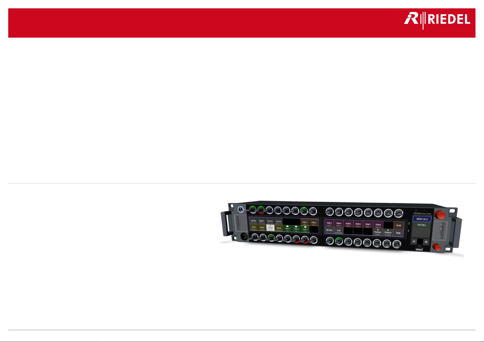
Communications proudly introduced the new 1200 series SmartPanel today. The RSP-1232HL represents a
quantum leap forward in workflow flexibility, power, and connectivity.
Featuring multiple full-color multitouch displays, 32 innovative hybrid-lever keys, the ability to leverage
apps for multifunctionality, and the ability to adapt easily to the various workflows in use today, this new
panel is poised to allow users to work the way they always have while opening up entirely new possibilities.
The two-year research and development effort behind the RSP-1232HL panel involved input from many
users and industry pros. Every aspect of existing panel technology was evaluated, from the spacing of
components to their look and feel. The result is a 32-key user interface with each lever key having an
integrated rotary encoder that provides control over parameters in the same location as the key. The levers
have been meticulously designed to have the perfect form, weight, comfort, responsiveness, and anti-
fatigue qualities to effectively redefine the way an intercom panel should feel.
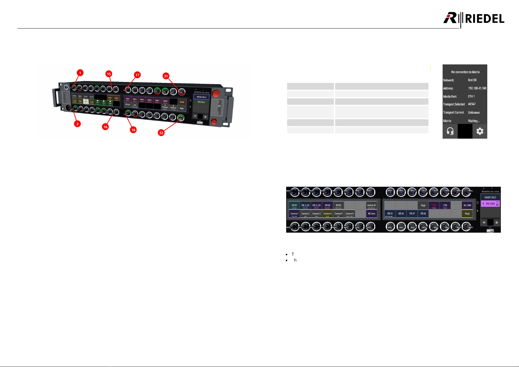
The RSP-1232HL has been designed to support varied workflows. Some comms users prefer “Talk & Listen”
workflows where the user chooses what to listen to from an initially silent panel. Other workflows prefer a
“Talk & Mute” workflow where users start with a panel that broadcasts everything, with the users selectively
choosing which signals to turn off. Users decide which mode they prefer on a per-panel basis.
Inventing a panel from scratch also enables new features that greatly aid in making the panel easier to
understand for users. Riedel’s new Logical Groups concept allows users to choose custom colors for either
the key labels or the LED rings that are positioned around each key. Each key label has an eight-character
main label, a 16-character sub-label, and user-defined icon labels. Along with that is an icon-based
signaling mechanism to tell the user what state each key is in at any point in time. Open Mic, Muted Key,
Incoming Beep, or Port Busy are easy to read and understandable at a glance. Users can get as much or as
little information about any given key as needed.
Connectivity is always a big consideration for Riedel, and it was important that the new panel take
advantage of both the AES3 digital connectivity the company has always used along with the SMPTE 2110-
30 (AES67) connectivity that it has embraced in recent years. AES67 connections are two fiber SFPs and two
RJ45 connections that create a variety of daisy-chaining and redundancy options to realize extraordinary
cabling flexibility.
Other features include stereo, phase-accurate speakers; front-panel mic mute and sidetone adjustments
and front/rear USB; GPIO 4-and wire ports.

8
1200 Series SmartPanels 1.0 User Manual
01-000HB03EG-A10
2 RSP-1232HL SmartPanel
The unique feature set of Riedel's RSP-1232HL SmartPanel includes 3 high-resolution, sunlight readable,
multi-touch color displays and 32 lever keys including rotary encoders in 2RU.
Features
·
32 lever keys
·
3 high-resolution, sunlight-readable displays
·
Integrated power supply
·
2 SFP slots
·
2 USB ports
·
2 Ethernet connectors
·
2 Matrix connectors (RJ45/BNC)
·
1 Expansion connector (future use)
·
NFC-/Bluetooth connectivity (future use)
·
1 Management connector (future use)
·
1 SD card slot
·
1 Displayport (future use)
·
3 GPI-In
·
3 GPI-Out
·
2 Analog audio
·
2 Headset connector (RJ45)
·
removable gooseneck microphone
·
internal microphone (future use)
·
exchangeable Headset connector (mono/stereo)
·
2RU
2.1 Operating Elements
figure 5: RSP-1232HL (front view)
figure 6: RSP-1232HL (rear view)
Panel Microphone Connector (6.3 mm jack)
1×
Key-Displays (Touchscreen)
2×
Lever Keys with integrated Rotary Encoders with push functionality
32×
Panel Microphone (internal, future use)
1×
Light Sensor (future use)
1×
Rotary Encoder (big) with push functionality
1×
Speaker (left + right)
2×
Headset Connectors (front: XLR / rear: RJ45)
1× / 2×
NFC Antenna / Bluetooth-Antenna (future use)
1× / 1×
Info-Display (Touchscreen)
1×
USB Connectors (front: Type-A / rear: Type-C)
1× / 1×
Rotary Encoder (small) with push functionality
1×
SFP Slots ETH3/ETH4
2×
Micro SD Card Slot
1×
Ethernet Connectors ETH1/ETH2 (RJ45)
2×
Expansion Connector EXP (RJ45)
1×
Matrix Connectors (AES3, RJ45/BNC)
2×
Displayport DP (future use)
1×
GPI Inputs / GPI Outputs (D-Sub-9, female/male)
3× / 3×
Analog Audio Inputs / Outputs (RJ45)
2×
Power Supply (mains input)
1×
Fan
1×
Management Connector MGNT (RJ45, future use)
1×
All Ports and Pinouts can be found in chapter Ports / Pinouts.

9
1200 Series SmartPanels 1.0 User Manual
01-000HB03EG-A10
2.2 Status LEDs
figure 7: RSP-1232HL (front status LED positions)
figure 8: RSP-1232HL (rear status LED positions)
The meaning of the Status LEDs in normal operation is listed in the following table:
Panel
Microphone
white
Panel microphone active, Headset deactivated
off
Headset active, Panel microphone deactivated
LED Ring
(top / bottom)
RGB
Depending on operation mode:
·
Group-Color
·
Signalization
Rotary Encoder
(big)
red blinking
Speaker muted
off
Speaker active
Rotary Encoder
(small)
red blinking
Microphone muted
off
Microphone open
Ethernet
(left)
green
Activity
off
No activity
Ethernet
(right)
yellow
100 Mbit/s link to the Intercom Network present
green
1 Gbit/s link to the Intercom Network present
off
No link
Expansion / Management
(left)
orange
Link ok
off
No link
Expansion / Management
(right)
yellow
Activity
off
No activity

10
1200 Series SmartPanels 1.0 User Manual
01-000HB03EG-A10
2.3 Lever Key Numbering
The lever keys are numbered as follows:
figure 9: Numbering of lever keys
2.4 Power-Up
Connect the RSP-1232HL with the mains voltage and wait until the SmartPanel has booted.
If the SmartPanel is not connected to a matrix, you will see the
following contents in the info display on the right:
Info-display
Function
Network
State of the audio network.
Address
IP address of the AES67 port.
Media Port
Selection of the Ethernet-port that is
connected to the AES67 network.
Transport Selected
Shows the current selected transport mode.
Matrix
State of the connection to the matrix.
figure 10: Info-display (no
connection)
If the SmartPanel is connected to the matrix, the matrix status changes to 'RX/TX OK' before the default
view is displayed.
figure 11: RSP-1232HL (connected with matrix)
·
The name (key label) of the corresponding channel is displayed below/above each lever key.
·
The subtitle (16-char subtitle) of the corresponding channel is displayed in the second line.

11
1200 Series SmartPanels 1.0 User Manual
01-000HB03EG-A10
2.5 Info-Display
The Info-display is located on the right side of the
SmartPanel.
·
Switching of Key-Banks (by prolonged touch)
·
Indication of active functions
·
Switching between panel- and headset operation
·
Open the panel menu
figure 12: RSP-1232HL (Info-Display)
Indication and switching the active Key-Bank.
Various symbols signal events on the corresponding Key Bank.
Beep symbol
If at least one channel on the inactive Key-Bank has an
incoming beep, the Beep symbol is displayed.
Talk-symbol
This symbol depends of the operation mode:
Talk/Listen
If at least one channel on the Key-Bank has an
active call, the Talk symbol is displayed.
Talk/Mute
Mute symbol
(Listen symbol)
This symbol depends of the operation mode:
Talk/Listen
If at least one channel on the Key-Bank listens to a
remote station, the Listen symbol is displayed.
Talk/Mute
If at least one channel on the Key-Bank is muted,
the Mute symbol is displayed.
Speaker symbol
(Headset symbol)
Switching between speaker and headset.
Speaker
SmartPanel speaker and microphone are active.
Headset
The connected headset is active.
Gear symbol
Opening the panel menu.
2.6 Reset
A restart of the SmartPanel can be forced in the panel menu "Service > Reboot Panel".
2.7 Panel-Menu
Basic information and settings of the SmartPanel can be displayed and modified in the Panel menu.
Ø
Touch the gear icon on the Info-Display to open the Panel
menu.
Info-display
Function
Transport
Set Transport Mode (AES3 or AES67)
Brightness
Adjust brightness off displays and LEDs
Device-Info
Show SmartPanel information
Network
Show/edit network settings
Matrix
Show Matrix information
Service
Stores a log file and reboots the SmartPanel
figure 13: Panel menu
In the Panel menu, keys can be navigated as follows:
Turning the lower,
small rotary encoder
·
Select the next / previous menu item
·
Change values / settings
Pushing the lower,
small rotary encoder
Enter selected menu item
BACK icon
in the Info-display
Back to parent menu item
ESC icon
in the Info-display
Cancel entry
OK icon
in the Info-display
Confirm entry
HOME icon
in the Info-display
leave menu / back to main view

12
1200 Series SmartPanels 1.0 User Manual
01-000HB03EG-A10
2.7.1 Transport
The menu Transport allows selecting the protocol that is used to connect the SmartPanel with a matrix.
Info-display
Function
Current Mode:
Shows the current used mode.
Selected Mode:
Selection of the mode to be used:
Auto
The SmartPanel selects the mode automatically to establish a successful
connection to a matrix.
AES3 Cat
The SmartPanel establishes a connection via RJ45 matrix connector.
AES3 Coax
The SmartPanel establishes a connection via BNC matrix connector.
AES67
The SmartPanel established a connection via the Ethernet-port defined
for using AES67 (see panel-menu: Network>AES67: Media-Port).
2.7.2 Brightness
The menu Brightness allows adjusting the display and LED brightness between 10% and 100%.
Info-display
Function
Display Brightness:
Adjusting the brightness of the displays.
LED Brightness:
Adjusting the brightness of the key rings.
2.7.3 Device-Info
The menu Device-Info shows information about the SmartPanel.
Info-display
Function
Date:
Shows the current date.
FW Version:
Shows the current firmware version.
SN#:
Shows the serial number of the SmartPanel.
2.7.4 Network
The menu Network allows showing/editing network settings.
The menu AES67 allows configuring the AES67 interface.
Info-display
Function
IP Address
Static IP-address of the AES67-port.
Subnet Mask
Network mask of the AES67-port.
Gateway
Gateway of the AES67-port.
SIP Port
Selection of the SIP-port. (Standard 5060)
Media Port
Selection of the Ethernet-port (ETH1...4) that is connected to the AES67 network.
2.7.5 Matrix
The menu Matrix shows information about the connected Matrix.
Content is only available if the SmartPanel is connected with a Matrix.
figure 14: Matrix
Display
Function
Net
Net number of the connected matrix.
Node
Node number of the connected matrix.
Bay
Bay number of the connected matrix.
Port
Port number of the connected matrix.
Room
Shows the Room code (if applied).
Name
Name of the SmartPanel.
Firmware-Version
Current version of the firmware of the connected matrix.
Bootloader-Version
Current version of the Bootloader of the connected matrix.
Emergency-Version
Current version of the Emergency-firmware of the connected matrix.
CurAPi
Shows the active audio patch.
PAN
Number of the panel in the Artist.
Alarm
Number of alarms in the connected matrix.
Node IP
IP-address of the connected matrix.
OnCall
Number of incoming calls to the SmartPanel that are active when the matrix menu is
opend.
Datum
Shows the current date of the connected matrix.
Uhrzeit
Shows the current time of the connected matrix..
MIC conf
The microphone setting of the panel can be changed between dynamic and electret
by using the lever key 29.
HS conf
The microphone setting of the headset can be changed between dynamic and
electret by using the lever key 31.
Key in the Info-display to return to the parent menu item.
Key in the Info-display to return to the main view.

13
1200 Series SmartPanels 1.0 User Manual
01-000HB03EG-A10
2.7.6 Service
The menu Service allows storing logfiles and rebooting the SmartPanel.
Info-display
Function
Log Files
Stores the internal log file onto an USB stick.
This data is used by the Riedel service for analysis and troubleshooting.
Save to USB
Saves the log file "report_*.tgz" to a previously inserted USB stick.
The file is saved in the folder "\Riedel\reports".
Reboot Panel
Reboot now
Restarts the SmartPanels.
Cancel
Exits the menu item and jumps back one level.
2.8 Replacing the Air Filter
The air filters are located on both device sides.
Ø
Use your fingers to pull out the
grille including the air filter on the
upper side.
Ø
Remove the air filter out of the
grille.
Ø
Push the new/cleaned air filter in
the grille.
Ø
Insert the grille into the bottom of
the SmartPanel first and then
press it evenly.
Ø
Repeat this step on the opposite
side of the chassis.

14
1200 Series SmartPanels 1.0 User Manual
01-000HB03EG-A10
3 SmartPanel Firmware
The firmware version 1.0 contains following app:
App
License
Version
Description
Intercom app
RSP-1232HL-APP-PRO
1.0
Standard App for
Intercom functionality.
These licenses are
already pre-installed on
the SmartPanel.
AES3 app
RSP-1232HL-LIC-AES3
1.0
Standard Apps to use the
AES3 interface.
3.1 Licensing
The 1200 series SmartPanels need license files to activate the apps running on the panel. If a panel is not
already licensed by Riedel, the license file is provided by your local distributor. The name of the license file
needs to be equal to the serial number of the panel where the license will be installed. The serial number
of a SmartPanel is 13 digits long and contains numbers only (e.g. "1234512345678"). The license file is a
"bin"-file (e.g. "1234512345678.bin"). Every license file is only readable by the panel matching the serial
number.
3.2 Intercom App
The first SmartPanel app turns the SmartPanels in innovated and intelligent intercom panels.
Riedel's intercom app can be quickly and easily upgraded to the desired edition, without changing any
hardware components.
This app requires a license file (RSP-1232HL-APP-PRO).
This license is already pre-installed on the SmartPanel.
Intercom App
Pro
Intercom Keys
32
Multi-Touch Displays
3
GPI (In/Out)
3/3
Audio I/O A
ü
Audio I/O B
ü
Headset A
ü
Headset B
ü
Expansion Panels
ü
Key-Banks
ü
Logical Groups
ü
3.2.1 Operation
This chapter describes the operation of the Intercom app of the SmartPanel:
Lever-Key Functions
Push the lever key up or down to trigger the function.
An activated function is indicated either by the lever keys' LED-ring or in the corresponding Key-
display.
The lever up key function is only latching.
The lever down key function depends on the configuration in Director: momentary, latching or
automatic (short press = latched / long press = momentary).
figure 15: Lever Key Functions

15
1200 Series SmartPanels 1.0 User Manual
01-000HB03EG-A10
Key-Display Functions
Touching the display of a key for half a second opens a drawer with various key functions. The dialog
will disappear after 3 seconds of inactivity.
figure 16: Key-Display functions
Sends a beep to the remote panel as long as the symbol is touched.
Activates/deactivates the listening function of the outgoing audio (Talk) on the remote panel
(monitor remote panel).
In Talk/Listen mode this functions is adequat to the lever up key function. In Talk/Mute mode
the activated monitoring function is indicated by an ear icon in the upper right area.
Sets the volume of the corresponding channel to normal level or switches off the muting.
Configures the copy/reply button to this port.
Volume Level
Master Volume
The upper, big rotary encoder is used to adjust the master volume of the SmartPanel. The volume
level is temporarily visualized by a vertical bar on the right side of the Info-display.
If the Headset mode is enabled, the volume of the connected headset is adjusted. The volume
levels of speaker and headset can be set independently.
Pushing the big rotary encoder will mute the speaker. This is indicated by a blinking LED inside
this rotary encoder.
figure 17: Master Volume

16
1200 Series SmartPanels 1.0 User Manual
01-000HB03EG-A10
Port Volume
The individual port volume is adjusted by turning the integrated rotary encoder in the respective
lever key. The volume level is temporarily visualized by a horizontal bar on the corresponding Key-
display.
Pushing the rotary encoder will mute the corresponding port. Muting is also possible by turning
down the volume completely. This is indicated by a mute icon in the corresponding Key-display.
figure 18: Port Volume
Sidetone Volume
The lower, small rotary encoder is used to adjust the sidetone level of the SmartPanel. The volume
level is temporarily visualized by a vertical bar on the left side of the Info-display.
Pushing the small rotary encoder will mute the microphone. This is indicated by a blinking LED
inside this rotary encoder.
figure 19: Sidetone Volume
The Sidetone function is always active on 1200 SmartPanels and must not be additionally
configured in the Director.

17
1200 Series SmartPanels 1.0 User Manual
01-000HB03EG-A10
Scroll Lists
To call up scroll lists configured in the Director on a 1200 smart panel, the respective configured rotary
encoder must be pressed twice (double-click). In the respective key display, either the alphanumeric
name search (Search) or the function type (C2 Port/L2 Port, ...) can now be selected by turning and
pressing the rotary knob in order to select a scroll list entry.
figure 20: Scroll Lists
3.2.2 Signalization
The LED-ring as well as the corresponding Key-display can be used to indicate any activity of the respective
port. The indication varies depending on the selected workflow mode (Talk/Mute or Talk/Listen).
Furthermore a symbol can be displayed in the corresponding ports.
The name (Key Label), subtitle (16-char Subtitle) and the symbol (Icon) of the port can be entered in the
Director software: right-click on the respective key > properties > 'General' tab.
figure 21: name / subtitle / icon of the port in the Director
Talk/Mute-Modus
In Talk/Mute mode, signaling is always shown via icons in the upper area in the key display.
Signal
Display
Description
Call
(active, outgoing)
The mic icon in the upper left area indicates an active
outgoing call.
Mute
(active)
The red mute icon in the upper right area indicates a
muted port.

18
1200 Series SmartPanels 1.0 User Manual
01-000HB03EG-A10
Talk/Listen-Modus
In Talk/Listen mode, the signalization depends on the configuration of the group color:
·
If the group color is indicated via the key ring, the signalization is indicated via the display.
·
If the group color is indicated via the display, the signalization is indicated via the key ring.
Signal
Display
Description
Call
(active, outgoing)
Signaling
via the Key-display
(Group color
via the LED-ring)
A red bar is displayed below
the title.
Signaling
via the LED-ring
(Group color
via the Key-display)
The lower part of the
LED-ring lights red.
Monitor
(listen, active)
Signaling
via the Key-Display
(Group color
via the LED-ring)
A green bar is displayed
above the title.
Signaling
via the LED-ring
(Group color
via the Key-display)
The upper part of the
LED-ring lights green.
Common Signalization
Signal
Display
Description
Call
(incoming)
The Key-display is highlighted (fade in / out) while a
call is incoming if the port is not muted.
Beep
(incoming)
The animated bell icon shows where the Beep being
received is coming from.
Beep
(outgoing)
The animated bell shows that the user is beeping a
remote panel.
Port occupied
This symbol indicates that the remote panel is
currently in a call.
Active Control Signal
This signal will cover all control functions in the Artist.
The user can choose to color the control signal in the
key function.

19
1200 Series SmartPanels 1.0 User Manual
01-000HB03EG-A10
3.2.3 Lever-Groups
The keys of the SmartPanel can be assigned into up to 16 groups.
For an easy identification each group has an separate group color.
The group color can be selected in Key Properties in the Director software: right-click on the respective key
> Properties > 'General' tab > 'Group color'.
The group color is indicated either in the key ring or in the display of the SmartPanel.
This setting is done in Panel Properties in the Director software: right-click on the respective SmartPanel >
Properties > 'UI Config' tab > 'Group color'.
figure 22: group color per key in Director (Key
Properties)
figure 23: indication of group color in Director (Panel
Properties)
The key signalization is indicated in the opposite way:
·
If the group color is indicated via the key ring, the signalization is indicated via the display.
·
If the group color is indicated via the display, the signalization is indicated via the key ring.
Group Color via Key Ring
Group Color via Display
Group-Color
(i.e. light blue)
Signalization
via the key ring
(only in Talk/Listen mode)
Signalization (Bars)
via the display
(only in Talk/Listen mode)
Group-Color
(i.e. light blue)
In Talk/Mute mode, signaling is always shown via icons in the key display.
3.2.4 Operation Mode
The RSP-1232HL offers two different ways of operation:
·
Talk/Listen
·
Talk/Mute
The desired mode can be set in the Director software (panel properties > 'UI Config' tab):
right-click on the respective SmartPanel > Properties > 'UI Config' tab > 'Panel operation mode'.
figure 24: workflow mode in Director
The following table shows the function of lever keys in both modes:
Lever Direction
Talk/Listen
Talk/Mute
up *1
Listen to outgoing audio (Talk) on a
remote panel (monitor remote panel)
Mute the incoming audio signal
down *2
·
Talk to a panel
·
Execute additional configured commands
*1 latching only
*2 auto, momentary and latching

20
1200 Series SmartPanels 1.0 User Manual
01-000HB03EG-A10
3.2.5 Key-Banks
Key Banks – a new take on shift pages – are layers of keys that are accessed by simply touching a button on
the screen. The Info-Display shows two key banks in the main. The user can switch between the key banks
by touching the respective name for 0.5 seconds. The active key bank is highlighted in the Info-Display by a
thicker border. Furthermore the color of the active Key-Bank is shown as border in both Key-Displays.
figure 25: View of selected Key-Bank
The name and color of the key baks can be entered / selected in the Director software:
right-click on the respective SmartPanel > Properties > 'UI Config' tab > 'Key Bank configuration'.
figure 26: name / color of key banks in the Director
This manual suits for next models
1
Table of contents
Popular Control Unit manuals by other brands

AI-Link
AI-Link WF-R710-RTU1 quick start guide

Emerson
Emerson Dixell XEC Supercap Installing and operating instructions

argon audio
argon audio POD manual

Total Control
Total Control QPI-PSL-201 installation guide

GEM
GEM 563 Installation, Operating and Maintenance Instructions for the Installer and the User

Anaren
Anaren A2530R24A user manual

Vexve
Vexve TERMOVAR Series Mounting and operating instructions

AVR
AVR AT90USB162 manual

Kuhse
Kuhse KEA 291 NSTR operating instructions

Rain Bird
Rain Bird EASY RAIN manual

Roger Technology
Roger Technology H70/101AC Instructions and Recomendations for the Installer

BS&B
BS&B 6400 Instruction and maintenance manual