manuals.online logo
Brands
  1. Home
  2. •
  3. Brands
  4. •
  5. Riello
  6. •
  7. Boiler
  8. •
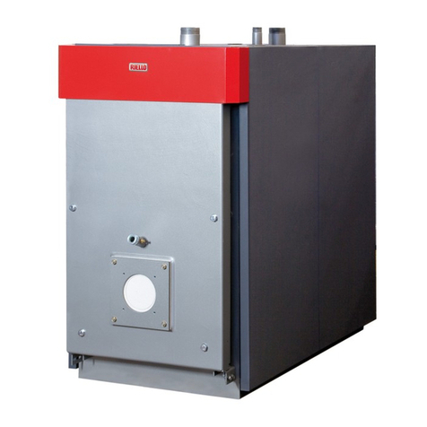
  9. Riello RTT 163 User manual

Riello RTT 163 User manual

cod. Doc-0079322 rev. 0 03/2016
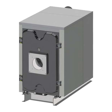
RT T 163-355
EN ASSEMBLY MANUAL
2
RANGE
MODEL CODE
RTT 163 20091302
RTT 195 20091303
RTT 227 20091304
RTT 259 20091305
RTT 291 20091306
RTT 323 20091308
RTT 355 20091309
ACCESSORIES
For the RTT 163-355 r boilers the following accessories are avai-
lable:
a. Two stage kit – 4031067
b. Storage heater probe – 20010103
In some parts of the booklet, some symbols are used:
9 = for actions requiring special care and adequate preparation
0 = for actions THAT MUST NOT be performed
Dear client,
Thank you for choosing a Rboiler, a modern and high quality
product, providing you with the utmost well-being and with a
high level of reliability and safety; and this is particularly the
case if entrusted to a RTechnical Assistance Centre which is
specically capable of carrying out routine maintenance, keep
it running at maximum efciency, with low running costs and
which has original spare parts if required.
This instruction booklet contains important information and
suggestions that should be observed for easy installation and
better use of the RTT 163-355 boiler.
Thank you once again
Riello S.p.A.
CONFORMITY
TheRTT 163-355 r boilers comply with:
−2009/142/EC (ex 90/396/EEC-Gas Directive)
−92/42/EEC (Efciency Directive)
−2006/95/EC (ex 73/23/EEC-Low voltage Directive)
−2004/108/EC (ex 89/336/EEC-Electromagnetic Compatibility
Directive)
−EN 303/1-2-3
−EN 60335-1/2
−EN55014-1/2
−EN 61000
This booklet, Cod. Doc-0079322 - Rev. 0 (03/2016) is composed of 12 pages.
3
1.1 INSTALLATION SPECIFICATIONS OF RTT CAST IRON
BOILERS
This installation manual is for certied and authorised installers
and technical assistance personnel, operating domestically and
abroad. The manual has the purpose that the cast iron boiler is
installed correctly.
9 Make sure that the room where the installation will occur
is suitable for the minimum dimensions set out in the bur-
ner's instruction booklet and that the base on which the
boiler will sit is adequate for its weight and dimensions.
9 It is the responsibility of the installers to ensure the neces-
sary safety conditions during all the assembly and installa-
tion phases; if the conditions are not optimal, adopt the ne-
cessary corrective measures before starting the installation.
9 The installation of the ON range cast iron boilers requires at
least 2 people, pay particular attention to the handling of
heavy components, in order to prevent the risk of injury to
people and damage to objects.
9 The boiler is supplied with all its components and some
installation equipment, the following assembly material is
included: silicon, applicator, brush, sealant for couplings,
Blakite, gloves and face mask
9 Carefully read the manual before installation, for any clari-
cations do not hesitate to contact the technicians of the
manufacturer or the retailer.
9 Be careful not to damage the painted components (body
and boiler cladding) when handling, assembling and when
connecting the burner and the ue gas pipe. Make sure that
all the technicians are aware of these warnings.
Thanking you for taking the time needed to read these in-
structions, we hope your installation goes well and we would
like to remind you that a good installation will ensure the boiler
continues to run well over time.
4
• If you do not have one, create a base suitable for the weight
and size of the boiler it needs to support, respecting the
provisions and the dimensions indicated in the technical
manual.
• Fix the rear element on the boiler base to the ground using
dowels.
• Clean the grooved prole of the ue gas seal of the rear ele-
ment with a brush or with a cloth and then ll it with silicon.
• Insert the insulating cord already ready in the groove as
shown in the illustration and x it with the silicon that was
applied previously.
• (Repeat the operations for the successive elements).
• Clean the housings of the ttings of the rear element and
put the sealing coating on them (in orange) to improve their
seal.
• (Repeat the same operations for all the intermediate ele-
ments and the front element).
• Clean the surfaces of the couplings and apply the sealant
coating on the surfaces that come into contact with the rear
element to enhance the seal. Insert the coupling into the
element.
• (Repeat the operations for the all the couplings).
5
• Pass the tie-rods (M10 x 200) into the assembly holes of the
rear element and the intermediate element.
• Using an M10 wrench, tighten the nuts at the ends of the
pins to bring the elements closer and in contact.
• Depending on the boiler model (number of intermediate
elements), the assembly operations described will have to
be repeated for each of the unnumbered intermediate ele-
ments.
• The last two intermediate elements are always marked by
the numbers 3, 2. Once the assembly of the unnumbered
intermediate elements has been completed, mount the
intermediate element with the number 3, followed by the
intermediate element 2. For clarication of the assembly
sequence, see the gure
9 The intermediate element with the number 3 that contains
the thermostat housing should necessarily be assembled in
the third row from the front side.
The front element, marked with the number 1, is the last one to
be tted.
6
Insert the M16 locking tie-rods into the relative holes and tighten
the nuts at the ends to bring the elements closer to each other.
Tightening torque: 7 kg·m
• The ue gas pipe is xed using 2 threaded bars, washers
and nuts.
• The size of the ue gas pipe varies according to the following
table:
Boiler model Flue gas pipe dimensions
RTT 163 180
RTT 195 180
RTT 227 180
RTT 259 250
RTT 291 250
RTT 323 250
RTT 355 250
Assembling the anges:
• Apply the silicon to the at ange seal and stick it to the
mounting surface of the rear element. Insert the assem-
bly screws into the at ange and with these x the ange
to the boiler outlet (top side) tightening the lock nuts. The
Thermix ange should be connected to the lower side of the
rear element (return) as shown in the gure.
7
• Once the anges have been assembled, pass over the outer
surfaces of all the boiler elements with Blakite stucco.
• Fill the body of the boiler with water and carry out a hydrau-
lic seal test lasting 10 minutes at a pressure lower than 9 bar.
• Check the gas seal along the lines of contact between the
elements.This check can be carried out with a mobile light
or a projector. Light the inside of the boiler and observe it
from the outside. Apply Blakite to the points that let light
lter through to the outside.
• Installation of the retarder turbulators:
Boiler model Second pass Third pass
Lower Upper
RTT 163 2 large 2 medium 2 small
RTT 195 2 large 2 medium 2 small
RTT 227 2 large 2 medium 2 small
RTT 259 2 large 2 medium 2 small
RTT 291 2 large 2 medium 2 small
RTT 323 2 large 2 medium 2 small
RTT 355 2 large 2 medium 2 small
• The front edge of the turbulators should not exceed the mid
point of the front element during positioning.
• The number of turbulators per boiler should be as indicated
in the table.
• The door of the boiler burner should be tted after the tur-
bulators have been installed.
• Insert the 4 tie-rods of the hinges of the door in the relative
holes on the front element. Connect the door of the burner
to the tie-rods inserted in the hinges, t the washers and
tighten the lock nuts until the pressure of the insulating cord
can be felt on the prole of the front element.
• Insert 2 screws M10 x 75 in the top part of the hinges taking
into account the door the side should open from.
• The burner door should be raised slightly during opening
and closing (bringing the door attachments above the hei-
ght of the hinges)
• The installation of the casing will begin after nishing the
assembly of the body.
8
• First of all, x the casing's assembly bracket to the front and
rear feet of the boiler.
• Connect each assembly bracket of the casing to the foot
of the boiler inserting two M8 x 25 screws in the holes of
the foot, as shown in the gure. Then tighten the screws,
locking them with nuts and washers.
• After xing the four brackets, proceed with tting the top
shelves.
• For the assembly of the two shelves, use the holes in the
front element and on the rear element of the boiler body, as
shown in the gure. As xing devices use the assembly pins
of the elements (slacken and tighten the nuts locking the
pins in the elements).
• After installing the brackets and the assembly shelves of the
shell, proceed with applying the insulation on the cast iron
body.
• The insulation of the body should be shaped to create the
housing for the thermostat. Use a 2 point stainless steel wire
to connect the insulation to the boiler body in such a way
that it is stable.
• Join the side panels to the pins on the brackets of the feet
and screw them to the top shelves with M8x20 screws as
shown in the gure.
9
• After installing the side walls, connect the control panel on
the top front wall of the casing.
• Insert the thermocouples (sensors) of the control panel
(thermostat, safety thermostat, thermometer) in the slots of
the panel.
• Rest the two support brackets on the top panel, with the
side with more holes facing upwards and lining up the ho-
les of the bottom side of the bracket with those of the cover
panel.
• Fix each bracket with three self-tapping screws 4.2x9.5 (not
supplied).
• Remove the cover of the electrical panel.
• Place the base of the control panel on the support brackets,
matching up the holes, then use six self-tapping screws
(supplied with the electrical panel) to secure it.
• After inserting the ends of the sensors, secure them so they
do not come out, then put back the cover of the control pa-
nel on the base.
• Put the oil supplied in the hole of the thermostat so as to
improve the sensitivity of the sensors.
• Fit the top panel into the slots of the casing by inserting the
four pins into the corresponding holes on the side panels.
•
10
• After tting the top and side panels of the casing, proceed
to install the rear insulating panel.
• The rear cover panel is composed of two parts that should
be xed with screws to the side panels.
• The assembly is nished with the installation of the rear pa-
nel cover.
• Once the assembly of the body, the control unit and the ca-
sing is nished, the boiler is ready for the installation of the
burner and the connections to the system and to the ue
gas pipe.
• The installation of the burner and the connections to the
system and the ue gas pipe should be carried out by an
authorised technician, in conformity with the regulations
and specications contained in the use and maintenance
manual.
11
RIELLO S.p.A.
37045 Legnago (VR)
Tel. 0442630111 - Fax 044222378 - www.riello.it
As part of the company’s ongoing commitment to perfecting its range of products, the appearance, dimensions, technical data,
equipment and accessories may be subject to variation.

Other manuals for RTT 163

1

This manual suits for next models

13

Other Riello Boiler manuals

Riello Residence PRO 32 KIS Manual

Riello

Riello Residence PRO 32 KIS Manual

Riello KIS Series Operation and installation manual

Riello

Riello KIS Series Operation and installation manual

Riello INSIEME EVO 32 B/100 S User manual

Riello

Riello INSIEME EVO 32 B/100 S User manual

Riello Start Condens 25 IS Operation and installation manual

Riello

Riello Start Condens 25 IS Operation and installation manual

Riello Residence PRO 32 KIS Guide

Riello

Riello Residence PRO 32 KIS Guide

Riello Condexa Pro2 EVO Series User manual

Riello

Riello Condexa Pro2 EVO Series User manual

Riello RTQ 3S Series Owner's manual

Riello

Riello RTQ 3S Series Owner's manual

Riello INSIEME EVOe K LN Series Manual

Riello

Riello INSIEME EVOe K LN Series Manual

Riello Vokera VISION PLUS 20 S User manual

Riello

Riello Vokera VISION PLUS 20 S User manual

Riello TAU 1750 N Service manual

Riello

Riello TAU 1750 N Service manual

Riello Family KIS Series Operation and installation manual

Riello

Riello Family KIS Series Operation and installation manual

Riello Family IS Operation and installation manual

Riello

Riello Family IS Operation and installation manual

Riello BSB 100 Operation and maintenance manual

Riello

Riello BSB 100 Operation and maintenance manual

Riello 7200 HP Series User guide

Riello

Riello 7200 HP Series User guide

Riello 7000 ACI 60 PLUS User manual

Riello

Riello 7000 ACI 60 PLUS User manual

Riello VOKERA Easi-Heat Plus Ci User guide

Riello

Riello VOKERA Easi-Heat Plus Ci User guide

Riello GITRE B/100 LN Manual

Riello

Riello GITRE B/100 LN Manual

Riello RESIDENCE KIS Operation and installation manual

Riello

Riello RESIDENCE KIS Operation and installation manual

Riello INSIEME CONDENS 26 B Manual

Riello

Riello INSIEME CONDENS 26 B Manual

Riello MINI LN Series User manual

Riello

Riello MINI LN Series User manual

Riello Vokera Vision C User manual

Riello

Riello Vokera Vision C User manual

Riello Vokera Mynute 20 VHE Release note

Riello

Riello Vokera Mynute 20 VHE Release note

Riello KV 130 - 28 User manual

Riello

Riello KV 130 - 28 User manual

Riello Start Aqua Condens 25 BIS Operation and installation manual

Riello

Riello Start Aqua Condens 25 BIS Operation and installation manual

Popular Boiler manuals by other brands

Glowworm Betacom 24 Installation and Servicing Manual

Glowworm

Glowworm Betacom 24 Installation and Servicing Manual

Glowworm 100sxi Installation and Servicing Manual

Glowworm

Glowworm 100sxi Installation and Servicing Manual

Cater Chef 688.190 operating instructions

Cater Chef

Cater Chef 688.190 operating instructions

WOODCO cogetherm Technical manual

WOODCO

WOODCO cogetherm Technical manual

Rinnai E75CN Installation & servicing instructions

Rinnai

Rinnai E75CN Installation & servicing instructions

WOODCO E-Compact 28kW S Model Installation & operation manual

WOODCO

WOODCO E-Compact 28kW S Model Installation & operation manual

AER MFC 3000 user manual

AER

AER MFC 3000 user manual

AER GF-110 Benchmark Series Installation, operation & maintenance instructions

AER

AER GF-110 Benchmark Series Installation, operation & maintenance instructions

Thermo Sphere TSEFB-P4.5 instructions

Thermo Sphere

Thermo Sphere TSEFB-P4.5 instructions

HeatLink ELBP TS Series Installation, operation and maintenance manual

HeatLink

HeatLink ELBP TS Series Installation, operation and maintenance manual

Glowworm SUSTAIN 25c -A Installation and maintenance instructions

Glowworm

Glowworm SUSTAIN 25c -A Installation and maintenance instructions

Viadrus U 22 C manual

Viadrus

Viadrus U 22 C manual

Sime 1R 6 OF user manual

Sime

Sime 1R 6 OF user manual

Slant/Fin SENTRY S-120EDP Installation and operating instructions

Slant/Fin

Slant/Fin SENTRY S-120EDP Installation and operating instructions

Centrometal PelTec 12-48 Technical instructions

Centrometal

Centrometal PelTec 12-48 Technical instructions

Unical S 24 manual

Unical

Unical S 24 manual

Baxi Luna Duo-Tec Instruction manual for users and fitters

Baxi

Baxi Luna Duo-Tec Instruction manual for users and fitters

Buderus Logano G234X Installation and service instructions

Buderus

Buderus Logano G234X Installation and service instructions

manuals.online logo
manuals.online logoBrands
  • About & Mission
  • Contact us
  • Privacy Policy
  • Terms and Conditions

Copyright 2025 Manuals.Online. All Rights Reserved.