Riels Instruments Srl �+39 049 8961771 �+39 049 717368 �www.riels.it �info@riels.it
All data and contents of this card are the exclusive property of Riels Instruments
Installation
Wiring Diagram
Electrical Connections
Operation
UAL 538 detector:
This must be installed in a dry location that respects the ambient
conditions given under 5.TECHNICAL DATA. If installed in a location
classied as “Hazardous” it must be installed in a cabinet for electrical
equipment constructed according to the regulations in force for the
class of danger concerned. The controller can be mounted on a DIN
rail and housed in a standard DIN enclosure.
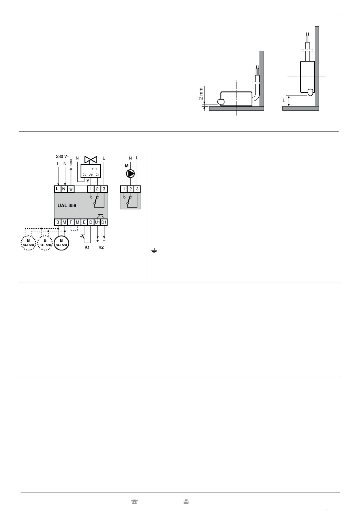
SAL 500 sensor:
This can be secured to the oor and in this position the poles detect
the presence of water at a height of two millimetres. If it is preferred
to measure the water at a different height, the sensor can be mounted
vertically on a wall so that the poles are at the desired height (L).
The relay switch if shown in the “Detector not powered” condition.
In the alarm state 2-3 = closed
L – 230 V ~
N – Neutral
B – Water-detecting sensor (up to three sensors can be
connected in parallel)
M – Pump
Y – Shut-off valve
K1 – Alarm reset
K2 – On-Off alarm output to be used for input D…E of
controllers with C-Bus
F-M – Without jumper = normal sensitivity
– With jumper = reduced sensitivity
– Terminal to be connected, for safety reasons, toplant earth
Proceed as follows:
• Separate base from cover after loosening the securing screws (2.3).
• Mount the base on the DIN rail and check that it is rmly anchored by the securing elements (2.4).
• Carry out the wiring according to the diagram and in compliance with the regulations in force and using :
– 1.5 mm cables for power supply, relay outputs and EARTH connection.
– 1 mm2 cables for the other connections.
NB: Maximum distance of water-detecting sensor: 50 metres
• Apply power (230 V~) and check its presence across terminals L and N.
• Remove power, replace cover on base and secure it with the two screws supplied (2.3).
You are advised not to insert more than two cables in a single terminal and, if necessary, to use an external junction box.
Under normal operating conditions (detector powered and not in alarm state) the output relay is live (3-1 closed and 3-2 open) and the LEDs “Alarm trig-
gered” and “Alarm recrded” on the facia are unlit. When the water level reaches the two poles of a sensor, the detector switches the relay output (3-2 closed
and 3-1 open), closes the optisolated switch and switches on the two LEDs on the facia. The relay output contacts can be used to operate a shut-off valve
or a pump for removing any water collected on the oor.
The K2 electronic optisolated switch can, on the other hand, be connected to a device with C-Bus communication system which will transmit the alarm to the
telemanagement PC.
If the water falls below the level of the two sensor poles, the optisolated switch re-opens, the “Alarm triggered” LED goes out, the relay remains in the alarm sta-
te and the “Alarm recorded” LED remains lit. This state continues until an engineer presses the K1 reset button and so restores the detector to its rest position.
If the space where the sensor is sited is particularly damp, unnecessary alarms may be triggered. The sensitivity can be reduced by inserting a jumper between
terminals F and M.
In the presence of oily residues on the surface of the water, the sensor, even after the water has been removed, may remain in the alarm state: in this event it is
necessary to clean the poles with an absorbent cloth.
NOTE :The pump must be equipped with a safety feature
that prevents dry operation.


