manuals.online logo
Brands
  1. Home
  2. •
  3. Brands
  4. •
  5. Visonic
  6. •
  7. Security Sensor
  8. •
  9. Visonic DISCOVERY PIR MCW - INSTALLER GUIDE User manual

Visonic DISCOVERY PIR MCW - INSTALLER GUIDE User manual

DE3632 1
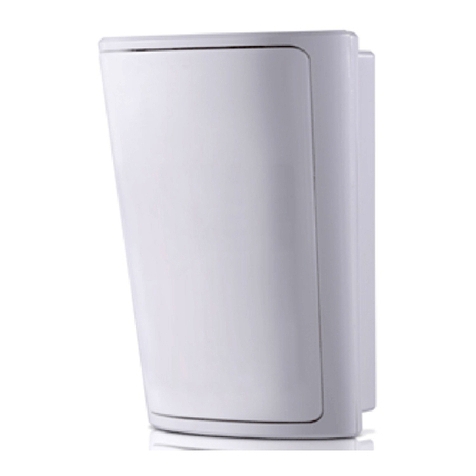
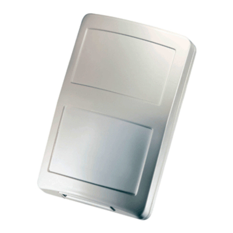
DISCOVERY PIR MCW
Wireless PowerCode PIR Detector
Installation Instructions
1. FEATURES
•Includes a fully supervised PowerCode transmitter
•Patented sophisticated motion analysis algorithm - True Motion
Recognition (TMR™)
•Two-position vertical adjustment for coverage pattern
•Integral swivel bracket for wall or ceiling installation
•Programmable motion event counter - ON (default) or OFF
•Front cover tamper switch
•Back tamper switch (option)
•Full stabilization achieved 30 seconds after power up
•After detection, the detector disables itself to save battery
power. It reverts to the ready state if there is no subsequent
detection throughout the following 2-minute period.
•Automatic termination of
walk-test after 15 minutes
•Low current consumption
•Microprocessor-controlled
temperature compensation
•Sealed chamber protects
the optical system
•White light protection
•Elegantly styled, sturdy
case
•Keyhole-shaped slot for
easy removal of PCB
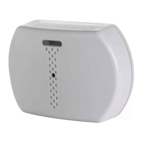
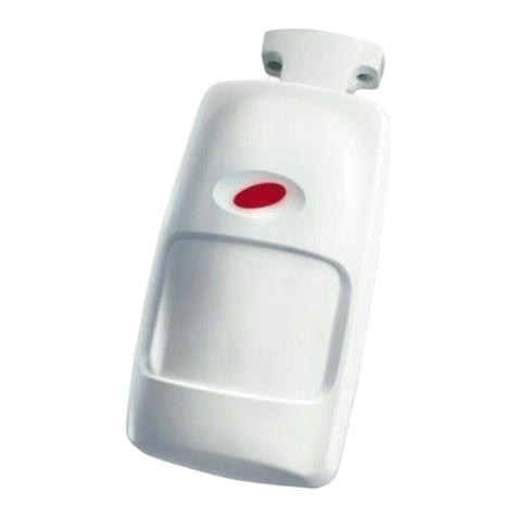
Figure 1. External View
2. SPECIFICATIONS
OPTICAL
Detector Type: Dual element low-noise pyroelectric sensor.
Detection Pattern: 90° wide angle lens with 19 dual zones in 3
detection layers. Max. coverage is 15 x 15 m (50 x 50 ft).
Adjustment: 2-position vertical adjustment scale: FAR and NEAR.
Figure 2. Coverage Pattern
ELECTRICAL
Internal Battery: 3V Lithium battery, type CR-2.
Nominal Battery Capacity: 750 mAh
Standby Current Drain: 0.015 mA
Transmit Current Drain: 20 mA (including LED)
Battery Life Expectancy: 3 years (for typical use)
Battery Supervision: Automatic reporting of battery status with
each alarm and with periodic supervision message.
FUNCTIONAL
True Motion Event Verification: 2 position selector - 1 (OFF) or
2 (ON) motion events.
Alarm Period: 3 seconds.
Visual Indications:
LED lights for about 3 seconds upon transmission of alarm &
tamper messages and upon each motion detection in the walk
test mode.
LED flashes during the power-up stabilization period, or after
restoring (pressing) the tamper switch.
LED does not light upon transmission of supervision messages.
Rearm Timer: Rearms the detector 2 minutes after the last alarm.
Timer disabled in the walk test mode.
WIRELESS
Frequency (MHz): 315 (U.S. version), 433.92, 868.95, 869.2625
or other frequencies according to local requirements.
Transmission Sequence: 3 data bursts at variable intervals
within 3 seconds.
Encoding: 24-bit ID, over 16 million possible combinations.
Total Message Length: 36 bits.
Tamper Alert: Reported when a tamper event occurs and in any
subsequent message, until the tamper switch is restored.
Supervision Message: Signaling at 60 minutes interval (U.S.
version), 15 minute interval (UK version) or according to local
standards.
MOUNTING
Height:
With bracket : Up to 3.6 m (12 ft)
Without bracket: 2 - 2.6 m (6.5 - 8.5 ft)
Installation Options:
With bracket: Surface or ceiling
Without bracket: Surface or corner
Bracket Adjustment: 20° downward, 20° left and right.
ENVIRONMENTAL
RFI Protection: >30 V/m up to 1000 MHz.
Operating Temperatures: -10°C to 50°C (14°F to 122°F).
Storage Temperatures: -20°C to 60°C (-4°F to 140°F).
Compliance with Standards: Designed to meet FCC Part 15
and Directive 1999/5/EC of the European Parliament.
EN 50131-1, Grade 2, Class II
PHYSICAL
Dimensions (H x W x D): 117 x 65 x 47 mm.
(4-5/8 x 2-9/16 x 1-7/8 in.).
Weight: 92 g(3.25 oz) without bracket, 107 g (3.75 oz) with bracket.
Color: White
PATENTS: U.S. Patent No. 5,693,943
2 DE3632
3. INSTALLATION
3.1 Installation Hints
To minimize false alarms:
Do not aim at heat sources
Mount on solid, stable surfaces
Do not expose to air draughts
Do not install outdoors
Prevent direct sunlight from
reaching the detector
Keep wiring away from
electrical power cables
Do not install behind partitions
3.2 Battery Insertion
It is recommended to power up the detector and let the target
receiver “learn” the transmitter’s ID before actual installation. This
can be done only after battery installation.
A. Remove the front cover as shown in Figure 3.
Figure 3. Cover Removal
B. Insert the battery into the battery clip - observe polarity (see
Figure 4).
C. Press the tamper switch once and release it. This will
perform the reset necessary for smooth power up.
D. Put the cover on and observe the LED. It will flash until the
detector stabilizes (within about 30 seconds).
3.3 Enrolling the Transmitter ID
Refer to the target receiver’s installation instructions and follow the
procedure given there for “teaching” the transmitter's ID. It is much
easier to carry out this operation in close proximity to the receiver.
3.4 Mounting without Swivel Bracket
A. Remove the front cover as shown in Figure 3.
B. Loosen the vertical adjustment screw, slide the PCB down
and remove it via the “keyhole” (see Figure 4).
MOTION
EVENT
COUNT
JUMPER
RF
MODULE
VERTICAL
ADJUST.
SCREW
CORNER
MOUNTING
KNOCKOUT
(1 OF 6)
LITHIUM
BATTERY
LED
PIR
SENSOR
LED
CONTROL
JUMPER
FRONT
TAMPER
SWITCH
MOUNTING
KNOCKOUT
(1 OF 3)
SWIVEL
BRACKET
KNOCKOUT
ON
OFF
COUN TER
DISCOVERY
PIR MCW
FAR
NEAR
VERTICAL
SCALE
BACK
TAMPER
SWITCH
(OPTION)
ONOFF
LED
KEYHOLE
Figure 4. Inside View
C. Punch out the mounting knockouts at the base (for surface
mounting) or mounting knockouts at the angled sides of
the base (for corner mounting).
Attention! The unit has a back tamper switch (option) under the
PCB. As long as the PCB is seated firmly within the base, the
switch lever will be pressed against a special break-away base
segment that is loosely connected to the base (Figure 5). Be sure
to fasten the break-away segment to the wall. If the detector
unit is forcibly removed from the wall, this segment will break
away from the base, causing the tamper switch to open. It is
advisable to pierce the anti-tamper knockouts from within the
base outward, while pressing the rear surface of the break-
away segment against a piece of wood.
Figure 5. Anti-Tamper Break-Away Base Segment
D. Hold the base against the wall at the selected location, mark
the drilling points, drill the holes and attach the base to the
wall.
E. Return the PCB to its place: align the ”keyhole” with the
head of the vertical adjustment screw, press the PCB
against the base, slide the PCB up and temporarily tighten
the screw.
3.5 Mounting with Swivel Bracket
A. Remove the front cover as shown in Figure 3.
B. Loosen the vertical adjustment screw, slide the PCB down
and remove it via the “keyhole” (see Figure 4).
C. Punch out the large knockout in the round bulge at the top
part of the base (see Figure 6).
D. Assemble the bracket as shown in Figure 6.
Figure 6. Attaching the Bracket
DE3632 3
E. Rotate the bracket to the desired position (see Figure 7) but do
not yet tighten the screw fully.
Figure 7. Wall and Ceiling Positions of Bracket
F. Mark the points for drilling through the two mounting holes of the
bracket. Attach the bracket to the mounting surface.
G. Tilt down or swivel the detector to face the desired direction.
Figure 8 shows the tilt/swivel possibilities.
Figure 8. Tilt/Swivel Limits
3.6 Setting the Motion Event Counter
The location of the motion event jumper is shown in Figure 4.
Refer to Figure 9 below and mount the jumper as desired.
Figure 9. Motion Event Counter Setting Options
3.7 Setting the LED Control Jumper
ON Position: Setting the jumper as shown enables
the LED. Remember that the detector disables
itself for 2-minutes after detection!
OFF Position: Setting the jumper as shown
disables the LED.
Note: At power up or reset, the LED flashes for 30 seconds
regardless of the jumper position and then enters walk-test mode.
After 15 minutes the detector enters normal mode in which the LED
functions according to the LED control jumper position..
3.8 Vertical Adjustment
Refer to Figure 10. Loosen the vertical adjustment screw and
slide the printed circuit board up or down to obtain the desired
coverage. When done, tighten the screw well.
Figure 10. Vertical Adjustment
3.9 Walk Testing
Upon battery insertion or closing of the cover (which results in
closing of the tamper switch) the detector goes into walk-test mode
and automatically exits the mode after 15 minutes.
A. Set the motion event counter as required (see Paragraph 3.6).
B. Adjust the vertical angle as desired (see Paragraph 3.8).
C. Remount the cover and fasten the case closure screw. This
results in the resetting of the detector and the start of walk-
test mode.
D. Wait until the LED stops flashing (about 30 seconds).
E. Walk-test the entire protected area by walking slowly across
the detector's field of view, observing the LED. Pause for 5
seconds after each detection to allow the detector to complete
its 3-transmission sequence; the LED will light for about 3
seconds.
F. When the walk-test is completed (after 15 minutes), the
detector's setting automatically changes according to the LED
control jumper setting.
Notes:
1. The OFF setting is recommended to prevent unauthorized
people from tracing the detector’s coverage pattern.
2. If the LED is disabled, you may use the control panel’s visual
and audible indicators to verify proper function of the
detector.
Attention! To assure proper function of the detector, the
range and coverage area should be checked at least twice a
year. Furthermore, the user should be instructed to perform a
walk test at the far end of the coverage pattern to assure an
alarm signal prior to each time the alarm system is armed.
4. MISCELLANEOUS COMMENTS
4.1 Product Limitations
Visonic Ltd. wireless systems are very reliable and are tested to
high standards. However, due to their low transmitting power and
limited range (required by FCC and other regulatory authorities),
there are some limitations to be considered:
A. Receivers may be blocked by radio signals on or near their
operating frequencies, regardless of the code selected.
B. A receiver can only respond to one transmitted signal at a
time.
C. Wireless equipment should be tested regularly to determine
whether there are sources of interference and to protect
against faults.
4.2 Frequency Allocations for Wireless
Devices in European (EU) Countries
•433.92 MHz has no restriction in any EU member state.
•315 MHz is not allowed in any EU member state.
4 DE3632
•868.95 MHz (wide band) is allowed in all EU member states.
•869.2625 MHz (narrow band) is not restricted in any EU
member state.
4.3 Compliance with Standards
This device complies with the essential requirements and provisions of
Directive 1999/5/EC of the European Parliament and of the Council of
9March 1999 on radio and telecommunications terminal equipment.
The 315 MHz model of this device complies with Part 15 of the
FCC Rules. Operation is subject to the following two conditions:
(1) This device may not cause harmful interference, and (2) this
device must accept any interference that may be received,
including interference that may cause undesired operation.
The user is cautioned that changes or modifications to the
unit, not expressly approved by the party responsible, could
void the user's FCC authority to operate the equipment.
WARRANTY
Visonic Limited (the “Manufacturer") warrants this product only (the "Product") to the original purchaser only (the
“Purchaser”) against defective workmanship and materials under normal use of the Product for a period of twelve
(12) months from the date of shipment by the Manufacturer.
This Warranty is absolutely conditional upon the Product having been properly installed, maintained and operated
under conditions of normal use in accordance with the Manufacturers recommended installation and operation
instructions. Products which have become defective for any other reason, according to the Manufacturers
discretion, such as improper installation, failure to follow recommended installation and operational instructions,
neglect, willful damage, misuse or vandalism, accidental damage, alteration or tampering, or repair by anyone
other than the manufacturer, are not covered by this Warranty.
The Manufacturer does not represent that this Product may not be compromised and/or circumvented or that the
Product will prevent any death and/or personal injury and/or damage to property resulting from burglary, robbery,
fire or otherwise, or that the Product will in all cases provide adequate warning or protection. The Product,
properly installed and maintained, only reduces the risk of such events without warning and it is not a guarantee
or insurance that such events will not occur.
THIS WARRANTY IS EXCLUSIVE AND EXPRESSLY IN LIEU OF ALL OTHER WARRANTIES, OBLIGATIONS
OR LIABILITIES, WHETHER WRITTEN, ORAL, EXPRESS OR IMPLIED, INCLUDING ANY WARRANTY OF
MERCHANTABILITY OR FITNESS FOR A PARTICULAR PURPOSE, OR OTHERWISE. IN NO CASE SHALL
THE MANUFACTURER BE LIABLE TO ANYONE FOR ANY CONSEQUENTIAL OR INCIDENTAL DAMAGES
FOR BREACH OF THIS WARRANTY OR ANY OTHER WARRANTIES WHATSOEVER, AS AFORESAID.
THE MANUFACTURER SHALL IN NO EVENT BE LIABLE FOR ANY SPECIAL, INDIRECT, INCIDENTAL,
CONSEQUENTIAL OR PUNITIVE DAMAGES OR FOR LOSS, DAMAGE, OR EXPENSE, INCLUDING LOSS
OF USE, PROFITS, REVENUE, OR GOODWILL, DIRECTLY OR INDIRECTLY ARISING FROM
PURCHASER’S USE OR INABILITY TO USE THE PRODUCT, OR FOR LOSS OR DESTRUCTION OF
OTHER PROPERTY OR FROM ANY OTHER CAUSE, EVEN IF MANUFACTURER HAS BEEN ADVISED OF
THE POSSIBILITY OF SUCH DAMAGE.
THE MANUFACTURER SHALL HAVE NO LIABILITY FOR ANY DEATH, PERSONAL AND/OR BODILY
INJURY AND/OR DAMAGE TO PROPERTY OR OTHER LOSS WHETHER DIRECT, INDIRECT, INCIDENTAL,
CONSEQUENTIAL OR OTHERWISE, BASED ON A CLAIM THAT THE PRODUCT FAILED TO FUNCTION.
However, if the Manufacturer is held liable, whether directly or indirectly, for any loss or damage arising under this
limited warranty, THE MANUFACTURER'S MAXIMUM LIABILITY (IF ANY) SHALL NOT IN ANY CASE
EXCEED THE PURCHASE PRICE OF THE PRODUCT, which shall be fixed as liquidated damages and not as a
penalty, and shall be the complete and exclusive remedy against the Manufacturer.
When accepting the delivery of the Product, the Purchaser agrees to the said conditions of sale and warranty and
he recognizes having been informed of.
Some jurisdictions do not allow the exclusion or limitation of incidental or consequential damages, so these
limitations may not apply under certain circumstances.
The Manufacturer shall be under no liability whatsoever arising out of the corruption and/or malfunctioning of any
telecommunication or electronic equipment or any programs.
The Manufacturers obligations under this Warranty are limited solely to repair and/or replace at the
Manufacturer’s discretion any Product or part thereof that may prove defective. Any repair and/or replacement
shall not extend the original Warranty period. The Manufacturer shall not be responsible for dismantling and/or
reinstallation costs. To exercise this Warranty the Product must be returned to the Manufacturer freight pre-paid
and insured. All freight and insurance costs are the responsibility of the Purchaser and are not included in this
Warranty.
This warranty shall not be modified, varied or extended, and the Manufacturer does not authorize any person to
act on its behalf in the modification, variation or extension of this warranty. This warranty shall apply to the
Product only. All products, accessories or attachments of others used in conjunction with the Product, including
batteries, shall be covered solely by their own warranty, if any. The Manufacturer shall not be liable for any
damage or loss whatsoever, whether directly, indirectly, incidentally, consequentially or otherwise, caused by the
malfunction of the Product due to products, accessories, or attachments of others, including batteries, used in
conjunction with the Products. This Warranty is exclusive to the original Purchaser and is not assignable.
This Warranty is in addition to and does not affect your legal rights. Any provision in this warranty which is
contrary to the Law in the state or country were the Product is supplied shall not apply.
Warning: The user must follow the Manufacturer’s installation and operational instructions including testing the
Product and its whole system at least once a week and to take all necessary precautions for his/her safety and
the protection of his/her property.
1/08
W.E.E.E. Product Recycling Declaration
For information regarding the recycling of this product you must contact the company from which you orignially purchased it. If you are discarding this product and not
returning it for repair then you must ensure that it is returned as identified by your supplier. This product is not to be thrown away with everyday waste.
Directive 2002/96/EC Waste Electrical and Electronic Equipment.
The technical documentation as required by the European Conformity Assessment procedure is kept at:
UNIT 6 MADINGLEY COURT CHIPPENHAM DRIVE KINGSTON MILTON KEYNES MK10 0BZ. Telephone number: 0870 7300800, Fax number: 0870 7300801
VISONIC LTD. (ISRAEL): P.O.B 22020 TEL-AVIV 61220 ISRAEL. PHONE: (972-3) 645-6789, FAX: (972-3) 645-6788
VISONIC INC. (U.S.A.): 65 WEST DUDLEY TOWN ROAD, BLOOMFIELD CT. 06002-1376. PHONE: (860) 243-0833, (800) 223-0020. FAX: (860) 242-8094
VISONIC LTD. (UK): UNIT 6 MADINGLEY COURT CHIPPENHAM DRIVE KINGSTON MILTON KEYNES MK10 0BZ. TEL: (0870) 7300800 FAX: (0870) 7300801.
TEL: (0870) 7300800 FAX: (0870) 7300801 PRODUCT SUPPORT: (0870) 7300830
VISONIC GmbH (D-A-CH): KIRCHFELDSTR. 118, D-40215 DÜSSELDORF, TEL.: +49 (0)211 600696-0, FAX: +49 (0)211 600696-19
VISONIC IBERICA: ISLA DE PALMA, 32 NAVE 7, POLÍGONO INDUSTRIAL NORTE, 28700 SAN SEBASTIÁN DE LOS REYES, (MADRID), ESPAÑA.
TEL (34) 91659-3120, FAX (34) 91663-8468. www.visonic-iberica.es
INTERNET: www.visonic.com
©VISONIC LTD. 2010 DISCOVERY PIR MCW DE3632- (REV. 5, 09/10)


This manual suits for next models

1

Other Visonic Security Sensor manuals

Visonic DUO 220 User manual

Visonic

Visonic DUO 220 User manual

Visonic MCT-441 User manual

Visonic

Visonic MCT-441 User manual

Visonic TOWER 40 User manual

Visonic

Visonic TOWER 40 User manual

Visonic CLIP-4N User manual

Visonic

Visonic CLIP-4N User manual

Visonic NEXT PG2 - User manual

Visonic

Visonic NEXT PG2 - User manual

Visonic DISCOVERY QUAD MCW User manual

Visonic

Visonic DISCOVERY QUAD MCW User manual

Visonic NEXT PIR MCW User manual

Visonic

Visonic NEXT PIR MCW User manual

Visonic DE1260 DISCOVERY QUAD User manual

Visonic

Visonic DE1260 DISCOVERY QUAD User manual

Visonic MC-302V PG2 User manual

Visonic

Visonic MC-302V PG2 User manual

Visonic DISCOVERY DUO User manual

Visonic

Visonic DISCOVERY DUO User manual

Visonic SRN-2000 User manual

Visonic

Visonic SRN-2000 User manual

Visonic DISCOVERY K9-80 User manual

Visonic

Visonic DISCOVERY K9-80 User manual

Visonic NEXT PLUS PIR / K9-85 User manual

Visonic

Visonic NEXT PLUS PIR / K9-85 User manual

Visonic V-MOTION MCW User manual

Visonic

Visonic V-MOTION MCW User manual

Visonic GSD-441 PG2 User manual

Visonic

Visonic GSD-441 PG2 User manual

Visonic DISC MCW User manual

Visonic

Visonic DISC MCW User manual

Visonic DISC User manual

Visonic

Visonic DISC User manual

Visonic SD-304C PG2 User manual

Visonic

Visonic SD-304C PG2 User manual

Visonic DUET-AM C/O Assembly instructions

Visonic

Visonic DUET-AM C/O Assembly instructions

Visonic CLIP SMA User manual

Visonic

Visonic CLIP SMA User manual

Visonic CLIP MCW User manual

Visonic

Visonic CLIP MCW User manual

Visonic K-980W User manual

Visonic

Visonic K-980W User manual

Visonic TOWER-20AM PG2 User manual

Visonic

Visonic TOWER-20AM PG2 User manual

Visonic MP-802 K9-85 PG2 User manual

Visonic

Visonic MP-802 K9-85 PG2 User manual

Popular Security Sensor manuals by other brands

AC Tool Supply BACHARACH Tru Pointe 2100 Operation and maintenance

AC Tool Supply

AC Tool Supply BACHARACH Tru Pointe 2100 Operation and maintenance

Rosslare SA-01PW installation manual

Rosslare

Rosslare SA-01PW installation manual

STEINEL IS-FS 300 manual

STEINEL

STEINEL IS-FS 300 manual

LST B312NL Specification sheet

LST

LST B312NL Specification sheet

AGFA XD 17 user manual

AGFA

AGFA XD 17 user manual

Inficon Sensistor ISH2000 HySpeed operating instructions

Inficon

Inficon Sensistor ISH2000 HySpeed operating instructions

Macurco RD-VRF User instructions

Macurco

Macurco RD-VRF User instructions

Climax Technology IR-29 manual

Climax Technology

Climax Technology IR-29 manual

CLAS OE 3010 manual

CLAS

CLAS OE 3010 manual

Sonoff PIR3-RF user manual

Sonoff

Sonoff PIR3-RF user manual

SPX Radiodetection RD8200 Operation manual

SPX

SPX Radiodetection RD8200 Operation manual

SIM SIM2W-FLOOD-I installation instructions

SIM

SIM SIM2W-FLOOD-I installation instructions

PCB Piezotronics 4115K-07A Installation and operating manual

PCB Piezotronics

PCB Piezotronics 4115K-07A Installation and operating manual

Elkron DK500M-E manual

Elkron

Elkron DK500M-E manual

ZKTeco ZK-D4330 user manual

ZKTeco

ZKTeco ZK-D4330 user manual

Boltek LD-350 Installation & Operator’s Guide

Boltek

Boltek LD-350 Installation & Operator’s Guide

HW Group 1W-UNI quick start guide

HW Group

HW Group 1W-UNI quick start guide

Phoenix ISL SP-ARC user manual

Phoenix ISL

Phoenix ISL SP-ARC user manual

manuals.online logo
manuals.online logoBrands
  • About & Mission
  • Contact us
  • Privacy Policy
  • Terms and Conditions

Copyright 2025 Manuals.Online. All Rights Reserved.