Attention!
The operating conditions of the Detector in a controlled
environment must exclude the presence of substances
that reduce the catalytic activity of sensitive elements and
corrosive substances: acid and alkali vapors, halogens,
fumes of silicon, phosphorus, silicone lubricants, varnishes,
sealants, etc.
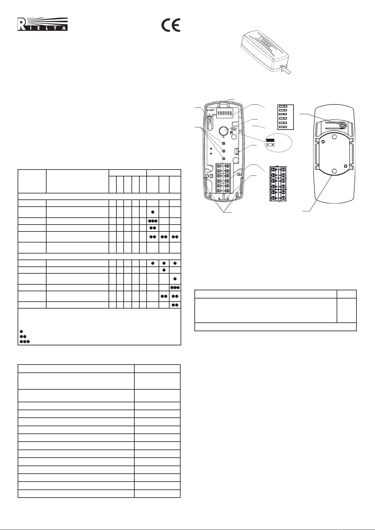
7 Connection
The Detector connection to data transmission system (DTS) or control
panel (CP) terminal device (TD) should be fulfilled in accordance with
connection pattern contained in relevant TD, DTS or CP exploitation
documents as per the Detector terminal blocks marking (see Figure 2,
position 6). Two openable holes (see Figure 2, position 8) are available
for wiring.
8 The Detector Controls
The IND DIP-switch is used for the Detector LED indication switching
ON.
The ATM DIP-switch is intended for choosing the signal processing
algorithm depending on type of secured construction (See Table 4).
Table 4
Secured construction ATM switch position
Safe or metal construction (cabinet, door, lattice) OFF
Automated Teller Machine (ATM) ON
DIP-switches S1, S2, S3 are intended for adjustment of destruction
channel sensitivity (see Table 5).
Table 5
DIP-switches Sensitivity
S1 S2 S3
ON ON ON Maximum
Minimum
ON ON OFF
ON OFF ON
ON OFF OFF
OFF ON ON
OFF ON OFF
OFF OFF ON
OFF OFF OFF User-operating mode (see Cl. 10)
9 Adjustment Procedure
Remove the housing cover and set the IND DIP-switch to ON position.
Set switch ATM to the position corresponding to the material of the
protected structure (see Table 4).
Switches S1, S2, S3 – in position ON, ON, ON (maximum sensitivity
level).
Switch on the power supply and check the formation of the LED
indication «Power on» and the «Normal» message. The presence of
the indication «Vibration» in the standby mode and the absence of
the effects listed in Table 4 display too high level of interference on
the protected object. If possible, eliminate the source of interference.
Set the MEM switch to ON position, switches S1, S2, S3 to OFF, OFF,
ON (minimum sensitivity level).
At the boundary of the protected area, apply a simulating
impact corresponding to the type of the protected structure (see
Table 6). If the «Destruction» message is generated and after it the
«Memory-destruction» LED indication (see Table 1) is ON, the sensitivity
adjustment can be considered completed.
In the absence of the notice «Destruction» – perform a step-by-
step sensitivity increase (see Table 5) until «Destruction» message is
generated after imitating impact.
When the sensitivity level is set, the Detector should not generate a
«Vibration» indication in the absence of any effects on the protected
structure.
After adjustment fulfillment, it is necessary to set the IND and MEM
switches in accordance with the security tactics chosen for the object.
Table 6
Methodic of a simulating impact
applying during sensitivity
adjustment
Supplementary technical data
Apply a steel plate to the surface
of the protected structure at the
outermost point of the controlled
area. Drill several holes in the
plate with a depth of 2 – 3 mm.
For each drilling, observe the LED
indication «Vibration», and after
the third one – «Destruction»
LED indication.
Cordless drill, drill ∅ (4 ± 0,5) mm, the
time of one drilling is not less than 10 sec.
Pause between drilling not more than
10 sec.
Electric drill, drill ∅ (4 ± 0,5) mm, the time
of one drilling is not less than 10 sec.
Pause between drilling not more than
10 sec.
10 User-operating mode
The user-operating mode, activated by DIP-switches (see Table 5),
is designed to adapt the Detector to a severe interference conditions
on a secured object by means of individual sensitivity adjustment to
different types of attacks.
In this mode, sensitivity adjustment is carried out by means of a
personal computer connected to the Detector via the serial interface
module «US-PI» (supplied by «RIELTA» JSC on a special order).
The procedure of the Detector adjustment in User mode is given in
the accompanying documentation for «US-PI».
11 Storage and Transportation
11.1 During the transportation the Detector in the package withstands:
- transport jolting with acceleration up to 30 m/sec2at impacts
frequency range from 10 to 120 per minute or 15.000 impacts with
the same acceleration;
- ambient temperature from minus 50 to plus 50 оС;
- relative air humidity up to 100 % at temperature plus 25 оС.
11.2 The Detector in original package may be transported by any
means of transportation in closed vehicles over any distances in
compliance with the existing shipping rules concerning the respective
means of transportation.
11.3 After transportation under the conditions different to exploitation
conditions the Detector shall be ready for operation after a maximum
of six hours.
11.4 The storage package shall be free from silica gel.
12 Manufacturer’s Guarantees
12.1 The Manufacturer guarantees conformity of the Detector to the
requirements of Specifications provided the transportation, storage,
installation and operation conditions are observed.
12.2 The guaranteed storage term of the Detector is 15 months since
the date of manufacture.
12.3 The guaranteed useful life is 12 months since the day of putting
into operation within the storage term guaranteed.
12.4 If non-conformity of the Detector to technical requirements
is detected during the guaranteed period if rules of operation are
observed, it shall be repaired by the Manufacturer.
13 Packing Certificate
Atm security vibration, tilt and gas detector «SH-VTG» has been
manufactured in compliance with the active technical documentation
and classified as fit for operation and packed by «RIELTA» JSC.
Packing date _______________________________
month, year
Rev. 4 of 17.03.20
v.2.3/v.2.3R
«RIELTA» JSC, www.rielta.com
Tel./fax: +7 (812) 233-03-02, +7 (812) 703-13-60,
Made in Russia