Electronstandart Pribor PGA-ESP BESTia User manual

PORTABLE GAS DETECTOR PGA-ESP
«BESTia»
Operating Manual
413411.001 OM
Saint Petersburg, 2019

Orginal Inv
Signature and date
Instead of №
Conv. Inv. №
Signature and date
GSKF.002.025.100 OM
Sheet
2
Rev
.
Document №
Signature
Date
Sheet
Content
1. Introduction..............................................................................................3
2. Designation................................................................................................3
3. Technical charactristics...........................................................................7
4. PGA-ESP explosionproof protection .....................................................8
5. Detector description and principle of operation ..................................8
6. Pre-operation procedures ..................................................................... 11
6.1. PGA-ESP turning on procedure ........................................................11
6.2. Gas detector adjustment.....................................................................12
7. PGA-ESP operation...............................................................................19
8. Connection of PGA-ESP to PC.............................................................20
9. Software ESP_config ............................................................................. 21
10. PGA-ESP calibration with SW ..........................................................25
11. Graphics................................................................................................27
12. Battery charging ..................................................................................31
13. Component parts and delivery set......................................................32
14. Service maintenance ............................................................................32
15. Verification ...........................................................................................32
16. Transportation and storage regulations............................................33
17. Marking ................................................................................................34
18. Acceptance certificate..........................................................................35
19. Certificate of Conservation.................................................................36
20. Manufacturer's warranty....................................................................37
21. Complaint Details.................................................................................38
Appendix А. PGA-ESP overall dimensions drawing.......................................39
Record of Revisions ............................................................................................40
Orginal Inv
Signature and date
Instead of №
Conv. Inv. №
Signature and date
GSKF.002.025.100 OM
Sheet
3
Rev
.
Document №
Signature
Date
Sheet
1. Introduction
1.1. This operation manual (OM) is a document confirming the main parameters and technical
characteristics of the PGA-ESP “BESTia” portable gas detector (hereinafter –PGA-ESP),
guaranteed by the manufacturer of JSC “Electronstandart-Pribor”.
1.2. OM is intended to familiarize with the device and the principle of operation of PGA-
ESP, as well as sets the rules for its operation.
1.3. Before you start using PGA-ESP, you must carefully read this operating manual.
ATTENTION! PGA-ESP should only be used for the following purposes and under the
conditions defined in this manual. Any external modification of the device, use in a
defective form or use of equipment not included in the delivery during installation - entails
the termination of the warranty.
2. Designation
Portable explosion-proof gas analyzers PGA-ESP "BESTia" are designed to measure the
concentration of flammable gases by volume fraction of oxygen, sulfur dioxide, nitrogen dioxide,
nitric oxide, hydrogen sulfide, carbon monoxide, chlorine in the air of the working area and signaling
when threshold values are exceeded.
The gas analyzer is an automatic device for personal protection of continuous operation.
Features and benefits
•Determination of gas concentrations vital for humans in the working area;
•User friendly screen interface;
•Application of 4 types of sensors at the same time to obtain data on -
omeasuring channel for combustible gases - infrared, thermocatalytic;
omeasuring channel of oxygen, hydrogen and toxic gases - electrochemical;
omeasuring channel LEL hydrocarbons - photoionization.
Field of application
PGA-ESP gas detectors are available in explosion-proof design and can be used in hazardous
areas of buildings and in open facilities in accordance with the explosion protection marking of the
device and regulatory documents governing the use of electrical equipment in hazardous areas.
Tables No. 1, No. 2, No. 3 and No. 4 show the conversion ranges and the limits of the
permissible basic error of the gas analyzer for all types of sensors used.
Orginal Inv
Signature and date
Instead of №
Conv. Inv. №
Signature and date
GSKF.002.025.100 OM
Sheet
4
Rev
.
Document №
Signature
Date
Sheet
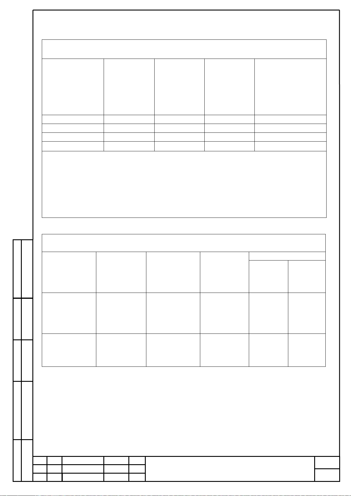
Table №1
Measurement ranges and error limits for gas with
thermocatalytic sensors (transducers)
Transducer type
Detected gas
The range of
indications of
the volume
fraction of the
determined
component, %
Range of
measurements
of the volume
fraction of the
determined
component, %
Permissible limits
basic absolute
errors, volume
fraction of the
determined component,
%
PGT-methane
СН4
0 to 4,4
0 to 2,2
±0,22
PGT-propane
С3Н8
0 to 1,7
0 to 0,85
±0,085
PGT-hydrogen
Н2
0 to 4
0 to 2
±0,2
PGT-acetylene
С2Н2
0 to 2,3
0 to 1,15
±0,115
Notes:
1) The measurement range in units of volume fraction of the determined component, %,
corresponds to the range of indications of the pre-explosive concentration of the determined
component from 0 to 100% LEL.
2) The measurement range in units of volume fraction of the determined component, %,
corresponds to the measurement range of the pre-explosive concentration of the determined
component from 0 to 50% LEL.
3) LEL values for the determined components according to GOST 30852.19-2002.
Table № 2
Measurement ranges and error limits for gas with
optical sensors (transducers)
Transducer type
Detected gas
The range of
indications of
the content of
the determined
component
Measuring
range of the
content of the
component to
be determined
Basic error limits
Absolute
Relative
PGO-methane
СН4
From 0 to 4,4 %
vol.
(from 0 to 100 %
LEL)
0 to 2,2 % vol
above 2,2 to
4,4 % vol.
±0,22 %
vol.
-
-
±10 %
PGO-propane
С3Н8
From 0 to 1,7 %
vol.
(from0 to 100
% LEL)
0 to 0,85 %
vol.
above 0,85 to
1,7 % vol.
±0,085 %
vol.
-
-
±10 %
Orginal Inv
Signature and date
Instead of №
Conv. Inv. №
Signature and date
GSKF.002.025.100 OM
Sheet
5
Rev
.
Document №
Signature
Date
Sheet
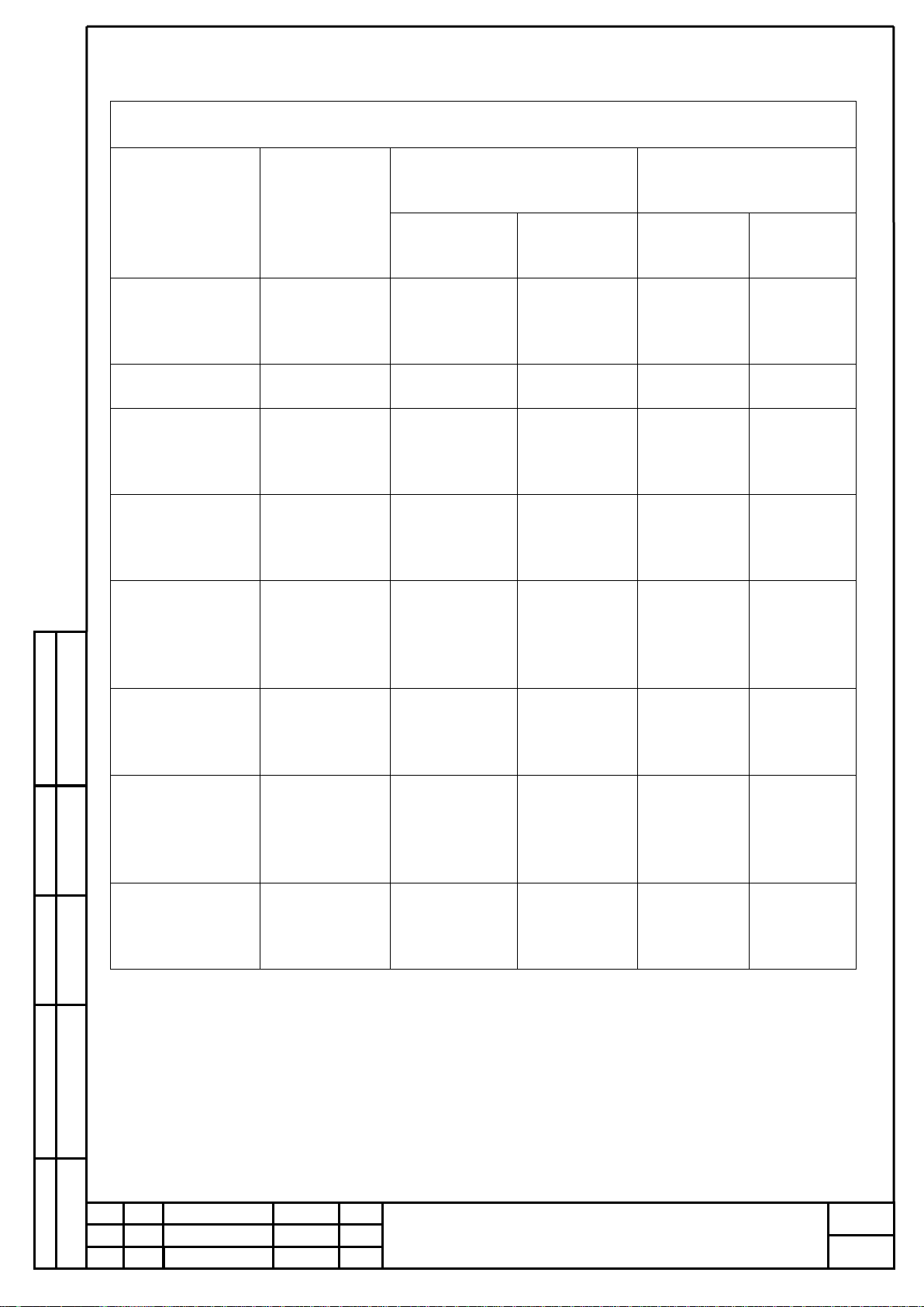
Table № 3
Measurement ranges and error limits for gas with
electrochemical sensors (transducers)
Transducer type
Detected gas
Range of measurements of the
content of the determined
component
Limits
basic error
ppm
mass
concentration,
mg/m3
absolute
relative
PGE- hydrogen
sulfide
H2S
from 0 to 7
ppm incld.
above 7 to 32
ppm
from 0 to 10
incld.
above
10 to 45
±2,5 mg/m3
-
-
±25 %
PGE- oxygen
О2
from 0 to 30 %
-
±(0,2+0,04С
Х) %
-
PGE-
carbon monoxide
СО
from 0 to 17
ppm incld.
above
17 to 103 ppm
От 0 to 20
incld. Above
20 to 120
±5 mg/m3
-
-
±25 %
PGE-nitrogen
dioxide
NO2
from 0 to 1
ppm incld.
above 1 to 10,5
ppm
От 0 to 2
incld.
above 2 to 20
±0,5 mg/m3
-
-
±25 %
PGE-
sulfur dioxide
SО2
from 0 to 3,8
ppm incld.
above
3,8 to 18,8
ppm
От 0 to 10
incld.
above 10
to 50
±2,5 mg/m3
-
-
±25 %
PGE- ammonia
NH3
from 0 to 28
ppm incld.
above
28 to 99 ppm
from 0 to 20
incld.
above 20
to 70
±5 mg/m3
-
-
±25 %
PGE-chlorine
Cl2
from 0
to 0,33 ppm
incld.
above 0,33
v 10 ppm
from 0 to 1
incld. above
1 to 30
±0,25
mg/m3
-
-
±25 %
PGE- Nitric oxide
NO
from 0 to 4
ppm incld.
above
4 to 100 ppm
from 0 to 5
incld.
above. 5
to 125
±1,25
mg/m3
-
-
±25 %

Orginal Inv
Signature and date
Instead of №
Conv. Inv. №
Signature and date
GSKF.002.025.100 OM
Sheet
6
Rev
.
Document №
Signature
Date
Sheet
Table № 4
Measurement ranges and error limits for gas with
photoionized sensors (transducers)
Transducer type
Detected gas
Range of measurements of the
content of the determined
component
Limits of
basic error
ppm
mass
concentration,
mg/m3
absolute
relative
PGF-
isobutylene-0-20
i-С4Н8
From 0 to 19,3
ppm
From 0 to 45
±12 mg/m3
-
PGF-isobutylene-0-
200
From 0 до 43
ppm incld.
Above 43 to 172
ppm
From 0 to 100
incld. Above
100
до 400
±25 mg/m3
-
-
±25 %
PGF-isobutylene-0-
2000
From 0 to 43
ppm incld.
Above
43 to 2000 ppm
From 0 to 100
incld. Above
100 to 4660
±25 mg/m3
-
-
±25 %
PGF - ethylene
С2Н4
From 0 to 86
ppm incld.
Above 86 to
171 ppm
From 0 to 100
incld. Above
100 to 200
±25 mg/m3
-
-
±25 %
PGF- benzene
С6Н6
From 0 to 1,5
ppm incld.
Above
1,5 to 9,3 ppm
From 0 to 5
incld. Above
5 to 30
±1,25 mg/m3
-
-
±25 %
PGF-methyl
mercaptan
СН3SН
From 0 to 0,4
ppm incld.
Above
0,4 to 3,9 ppm
From 0 to 1,0
incld. Above
1,0 to 10,0
±0,25 mg/m3
-
-
±25 %
PGF- diethylamine
С2Н5SН
From 0 to 0,4
ppm incld.
Above
0,4 to 3,9 ppm
From 0 to 1,0
incld. Above
1,0 to 10,0
±0,25 mg/m3
-
-
±25 %
PGF- diethylamine
С4Н11N
From 0 to 9,8
ppm incld.
Above
9,8 to 50 ppm
From 0 to 30
incld. Above
30 to 150
±7,5 mg/m3
-
-
±25 %
PGF- carbon
disulfide
СS2
From 0 to 3,1
ppm incld.
Above 3,1 to
15 ppm
From 0 to 10
incld. Above
10 to 47
±2,5 mg/m3
-
-
±25 %
PGF-903U - phenol
С6H6O
From 0 to 0,25
ppm incld.
Above
0,25 to 4 ppm
From 0 to 1
incld. Above 1
to 15,6
±0,25 mg/m3
-
-
±25 %
Orginal Inv
Signature and date
Instead of №
Conv. Inv. №
Signature and date
GSKF.002.025.100 OM
Sheet
7
Rev
.
Document №
Signature
Date
Sheet
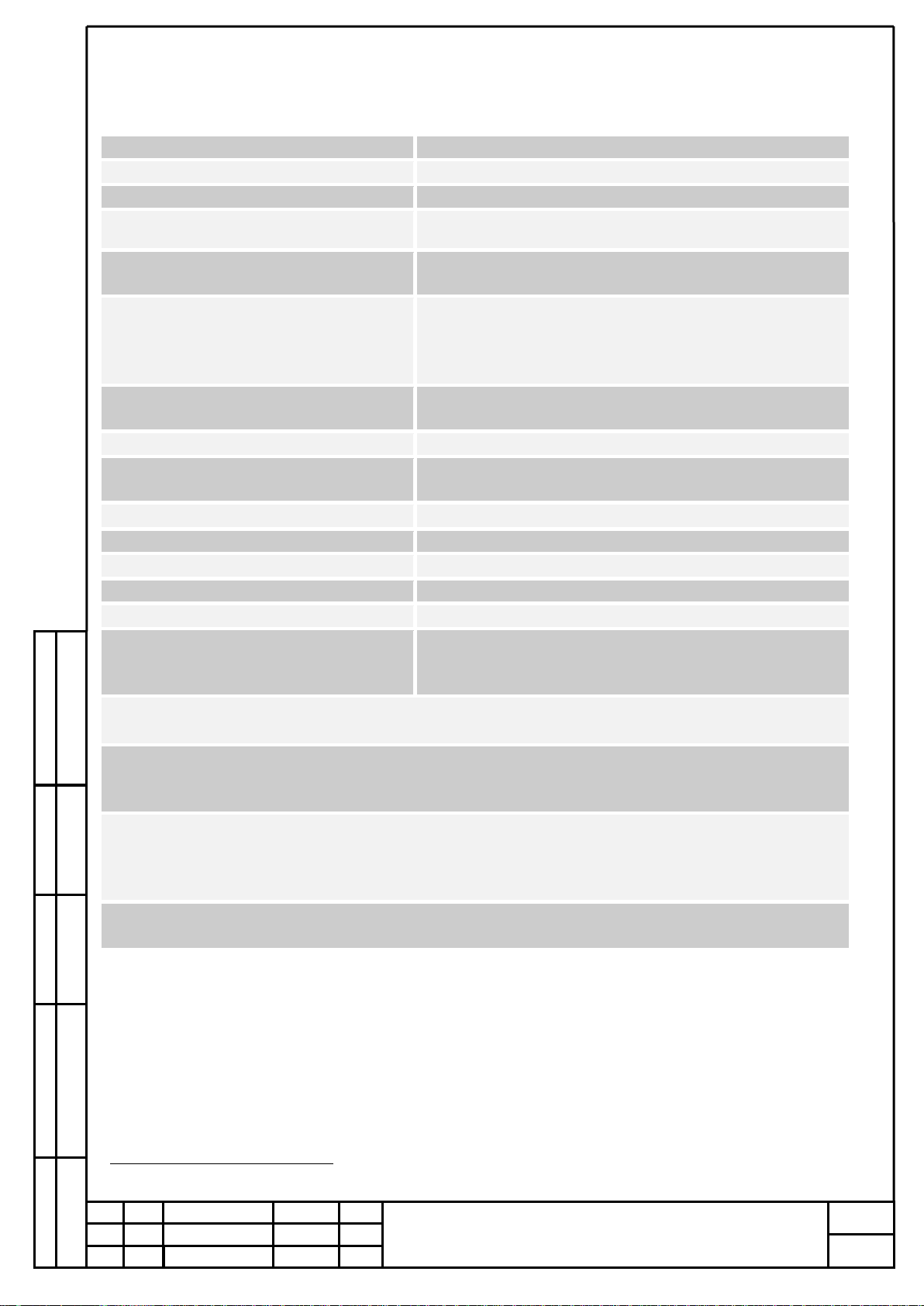
3. Technical characteristics
1
group P-1 of GOST 13320-81
2
group P-1 og GOST 13320-81
Overall dimensions
72х94х46 mm
Power consumption
not more 0,2 Watt in standby mode
Weight
not more 0,21 kg
Measuring ranges
See tables 1,2,3,4
Measurement ranges and basic error
limits
See tables 1,2,3,4
Gas detector provides vibration and
light-sound signaling when the
concentration of monitored gases
reaches fixed alarm thresholds
- sound signal 90 dB;
- LED indicators;
- display of symbols indicating the alarm
Output settling time
- no more than 30sec for combustible gases
- no more than 60 sec for toxic gases
Warm up time
no more than 10 min 1
Limits of permissible variation of
indications
no more than 0.2 in fractions from the limits of the
permissible basic error
Storage temperature
from - 50C to + 50 C
Power Supply
Ni-Mh batteries, ААА, 2 pcs.
Uptime
Not less 12 hours
MTBF
Not less 35 000 hours
Average life
Not less 10 years
The probability of trouble-free
operation of the gas analyzer in time
(running hours) 1 year
Not less 0,95
Limits of additional error from changes in ambient temperature for every 10C in the range from
minus 40 to 50C no more than 0.2 in fractions from the limits of the permissible basic error
The limits of the permissible additional error of gas analyzers from the influence of changes in
atmospheric pressure for every 10 kPa within the operating conditions of operation, 0.2 in fractions
of the limits of the permissible basic error
The limits of the permissible additional error of gas analyzers from the influence of changes in the
relative humidity of the analyzed medium, for every 10% within the operating conditions of
operation, 0.2 in fractions of the limits of the permissible basic error. Warming up time no more
than 10 min2
The gas detector is resistant to increased humidity of ambient air that meets the operating and
transportation conditions, up to 100% (non-condensing) at a temperature of 35 C
Orginal Inv
Signature and date
Instead of №
Conv. Inv. №
Signature and date
GSKF.002.025.100 OM
Sheet
8
Rev
.
Document №
Signature
Date
Sheet
4. PGA-ESP explosionproof protection
4.1 Explosion protection of detectors is ensured by the type of explosion protection
intrinsically safe electric circuit “ia”according to GOST R 31610.11-2014 (IEC 60079-11: 2011).
4.2. Explosionproof marking - Ex ia I / 0Ex ia IIСT4.
4.3. The degree of protection of the body of the gas analyzer from access to hazardous parts
(unit batteries) and from ingress of external solid objects and IP67 water in accordance with GOST
14254-2015.
4.4. On the back cover there is a warning sign «In hazardous areas DO NOT OPEN». Do NOT
charge the battery in a hazardous area. The battery must be charged outside the hazardous area.
Using the charger supplied along with the gas detector.
5. Detector description and principle of operation
The principle of operation of the gas detector is based on the conversion of the concentration
of the monitored gas with the help of gas thermocatalytic PGT transducers, of electrochemical PGEs,
optical PGOs into a DC voltage proportional to the concentration being converted, converting it to a
digital code and comparing it with predetermined threshold values.
Structurally, the gas detector is made in a single-block, proprietary plastic housing of
increased strength with protection from radio frequency interference. It has an ergonomic design,
rubberized side inserts for a comfortable grip, hold and prevent slipping, and also protects against
mechanical damage.
The button interface is designed for thumb control of both the left and the right hand.
On the front panel of the case are located:
- LCD display;
- protected keypad (4 buttons);
- two-color LEDs;
- sound emitter.
A strap mount is provided on the rear panel of the case, as well as a half-ring belt with a
fastener. On the bottom of the case is a protected USB connector for communication with a PC.

Orginal Inv
Signature and date
Instead of №
Conv. Inv. №
Signature and date
GSKF.002.025.100 OM
Sheet
9
Rev
.
Document №
Signature
Date
Sheet
The gas analyzer PGA-ESP has the following types of software:
- integrated firmware;
- Esp_Config for working with PC.
Integrated firmware performs the following functions:
- calculation of measurement results of the content of the determined components according
to data from the primary measuring transducer;
- diagnostics of hardware and software parts of the gas analyzer;
- maintaining and storing the event log (1000 unique records with the ability to automatically
replace old events with new ones);
- data exchange with PC via MODBUS-RTU protocol;
- comparison of measurement results with predetermined threshold values.
1. LED window
2. LCD backlit display
3. “UP”button
4. “Enter” button
5. Sound emitter
6. “Power” button
7. “Down” button
8. Sensors’ cell
9. Vibration emitter
10. Fixing clip
11. Electrochemical sensors
12. Thermocatalytic sensor
13. Sensor О2
14. Protection net
1
2
3
9
8
7
6
5
4
10
11
12
13
14

Orginal Inv
Signature and date
Instead of №
Conv. Inv. №
Signature and date
GSKF.002.025.100 OM
Sheet
10
Rev
.
Document №
Signature
Date
Sheet
Esp_Config for working with PC
The gas detector PGA-ESP has the ability to connect to a personal computer or laptop to work
with the Esp_Config software based on the Microsoft Windows OS. A detailed description of working
with the ESP_Config program is given in paragraph 9 of this operating manual.
.
Orginal Inv
Signature and date
Instead of №
Conv. Inv. №
Signature and date
GSKF.002.025.100 OM
Sheet
11
Rev
.
Document №
Signature
Date
Sheet
6. Pre-operation procedure
6.1. PGA-ESP turning on procedure
6.1.1 Detector is turned on by the
“Power” button
6.1.2. Alarm Checking:
A short beep sounds
Display flashes backlight
Blinking green LEDs
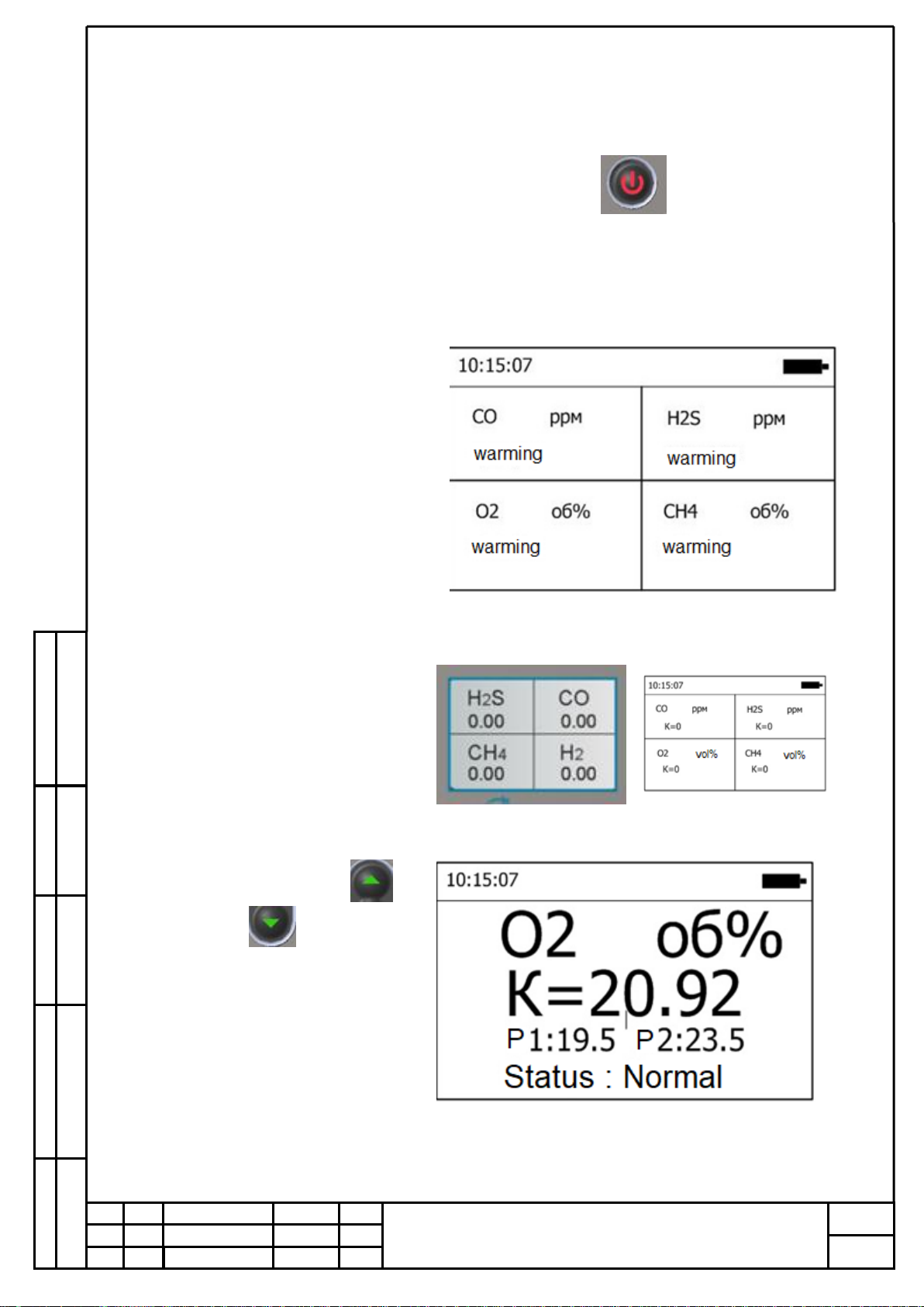
6.1.3. «Warm-up» mode
In this mode, transients end in the
sensors and constant values of the
output signals are set.
The channel measuring methane or
other explosive gas will be in the
“warm-up” mode longer than others
- this is normal
6.1.4. «Standby»Mode
In standby mode, the current
measured data, time, gas, units,
time, battery status should be
displayed
6.1.5. Using bottons “UP”
and “Down”can be selected
information for a specific selected
channel.
Information is displayed
sequentially for each channel from
the first to the fourth.
Orginal Inv
Signature and date
Instead of №
Conv. Inv. №
Signature and date
GSKF.002.025.100 OM
Sheet
12
Rev
.
Document №
Signature
Date
Sheet
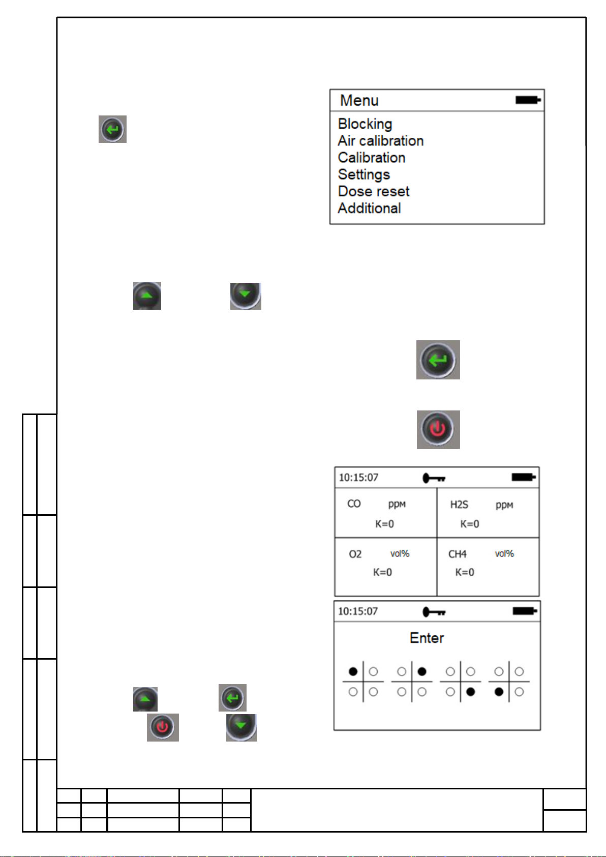
6.2. Gas detector adjustment
6.2.1. Go to the main menu of the device
settings by pressing the "Enter" button
6.2.2. The selection of items in the main
menu is carried out using the buttons
«UP»and «Down»
6.2.3. Selection confirmation –button
“Enter”
6.2.4. Cancel, exit to a higher level in the
menu through the "Power" button
6.2.5. «Lock»item allows you to block
accidental button clicks.
When locked in the status bar, we see the
key symbol.
When you click on any button, the
“unlock” window will open
Unlocking is carried out according to the
prompts displayed on the screen.
In order to unlock the device, you must
press the prompted buttons
«UP»«Enter»
«Power» «Down»

Orginal Inv
Signature and date
Instead of №
Conv. Inv. №
Signature and date
GSKF.002.025.100 OM
Sheet
13
Rev
.
Document №
Signature
Date
Sheet
6.2.6. The item “Calibr by air” sets the
level “0” for all channels except oxygen
according to the current state of the
environment. It establishes a normal
concentration of oxygen in the
environment - 20.95 ppm. Use only in the
“clean” zone, knowing in advance that
there are no additional impurities of
suspended gases in the environment, etc.
Choose by butoon
«Yes»and press
Air calibration done.
6.2.7. When selecting “Calibration”, a
window for selecting a channel for
calibration will open
After selecting a channel, the “action
selection” window appears
Where the channel number and type of
gas are indicated in the status window.

Orginal Inv
Signature and date
Instead of №
Conv. Inv. №
Signature and date
GSKF.002.025.100 OM
Sheet
14
Rev
.
Document №
Signature
Date
Sheet
6.2.8. “Zero” menu item
This is a zero concentration setting.
If you select “Yes”, a zero calibration is
performed.
If “No” is selected, the calibration value
remains unchanged.
6.2.9. “Concentration” menu item
Allows calibration using an arbitrary
concentration value. The value of the last
calibration concentration value is saved
(it is not necessary to enter the value for
the same cylinder each time).
Where: Кт –current concentration value
Uт–the current value of the signal on the ADC. It is convenient to use during calibration
to determine the end of calibration.
К- set value of the new concentration.
To enter the calibration concentration value, the number of decimal places is determined
by the measurement range and does not change manually.
The concentration input is carried out exclusively by the buttons of the selection buttons
«Up»and «Down»
When pressed once, the least significant digit changes by one in the corresponding
direction.
When holding the button, the least significant bit begins to change on its own.
Further holding the button accelerates changes and moves to the next digit.
The value increases to the upper value of the measuring range and so on in a circle.
When you release the button at the right time, we get the right number. If necessary, it
can easily be edited with a single click.

Orginal Inv
Signature and date
Instead of №
Conv. Inv. №
Signature and date
GSKF.002.025.100 OM
Sheet
15
Rev
.
Document №
Signature
Date
Sheet
To go to the “calibration” action, press the “select” button and use the buttons to
select:
“Yes” to calibrate or
“No” to exit to the “action selection” menu.
The device allows you to have up to 5 calibration points. This allows you to split the
measuring range up to four subranges. When the calibrated concentration falls into one of the
ranges where there is already a calibration point, an automatic replacement occurs. Necessary
and sufficient for work are 2 points, one of which is required calibration "0". You can calibrate
multiple times.
If, with a calibrated device, mix and set a low concentration, if the signal value is greater
than or equal to the value of high concentration (the same millivolt value), then calibration will
not be performed. The message “Invalid calibr” will be displayed on the screen.
Example.
The device is calibrated:
К=0 vol % U=10mV;
К=21 vol % U=1000mV;
Let's try to calibrate:
К=7 vol % U=1000mV;( or any number greater than 1000)
We get the answer:
“Invalid calibr”
6.2.10. “View”menu item
Allows you to view the current
calibration points and delete them if
incorrect calibration
To do this, select the point to be deleted
and press the “select" button »
In the window that appears, select “yes”
to delete or “no” if you want to leave the
calibration point unchanged
Orginal Inv
Signature and date
Instead of №
Conv. Inv. №
Signature and date
GSKF.002.025.100 OM
Sheet
16
Rev
.
Document №
Signature
Date
Sheet
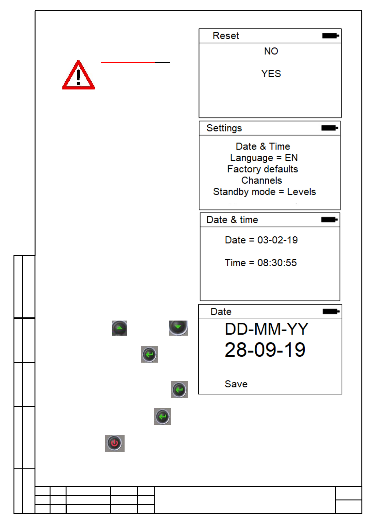
6.2.11. The menu item "Reset"
ATTENTION!!! This
menu item will reset all
instrument calibration
points when selecting
“YES”
6.2.12. The menu item "Settings"
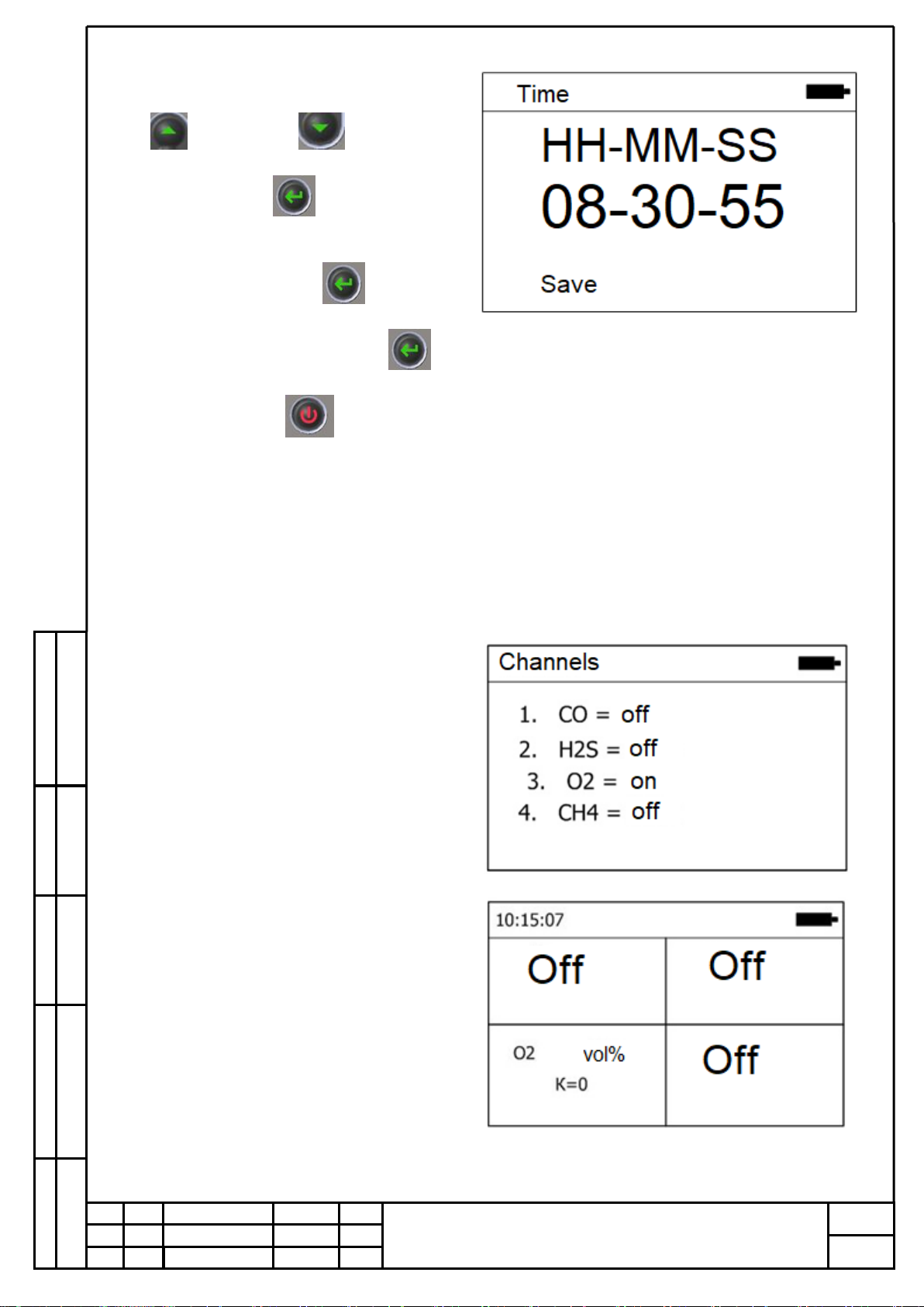
6.2.13. Menu item "Date & time"
The item "Date and time" allows you to
set the current date and time
Menu item "Date ..."
When the window is opened with the “up”
selection buttons and “down”
set the day of the month.
Use the "selection" button go to the
month setting. Then, in the same way, go
and set the current year.
The next press on the “selection”
will lead to the item “Save”. To save the
entered settings, press “select”
To correct the entered values, press the
cancel button. .
Also, using this button, you exit back to
the previous menu.
Orginal Inv
Signature and date
Instead of №
Conv. Inv. №
Signature and date
GSKF.002.025.100 OM
Sheet
17
Rev
.
Document №
Signature
Date
Sheet
Menu item "Time"
When the window is opened, the “Up”
and “Down” selection
buttons set the clock in 24-hour format.
Button "Select"
proceed to setting the minutes. Next, in
the same way, go and set the seconds.
Next click on "Select"
will lead to the “Save” item. To save the
entered settings, press “Select”.
To correct the entered values, click on the
“Cancel” button. . Так-же с
помощью этой кнопки происходит
выход обратно к предыдущему меню.
6.2.14. Menu item "Language"
Sets the interface language.
"RU" - Russian language
"EN" - English
Menu item "Factory defaults"
Returns instrument settings, including
calibrations, to factory settings.
6.2.15. “Channel”menu item
Allows you to block a particular channel
if necessary. If the channel is disabled, no
alarm on this channel works, on the
screen in standby mode - an empty sector
with the inscription “Off”.

Orginal Inv
Signature and date
Instead of №
Conv. Inv. №
Signature and date
GSKF.002.025.100 OM
Sheet
18
Rev
.
Document №
Signature
Date
Sheet
6.2.16. The menu item "Stanby Mode "=
Thresholds
Must remain in the preset position.
Thresholds do not change. A change can
only be entered with the shell.
6.2.17. The menu item "Additional"
6.2.18 Menu item "Info"
Displays information about the device
and its firmware version
6.2.19. Menu item “Archive”
Allows you to display messages about the
status of the device recorded in the
archive. After equality, the number of
entries in the archive is displayed. When
selecting the "Archive ..." item, we can
display one archive entry per screen. The
command line displays the sequence
number of the entry. Below is the date,
time and the recorded event itself.
For example, calibration channel number
3
The maximum number of records is
1000. The recording goes in a ring.
Record No. 1001 erases the events of
record No. 1 and becomes record No. 1
Orginal Inv
Signature and date
Instead of №
Conv. Inv. №
Signature and date
GSKF.002.025.100 OM
Sheet
19
Rev
.
Document №
Signature
Date
Sheet
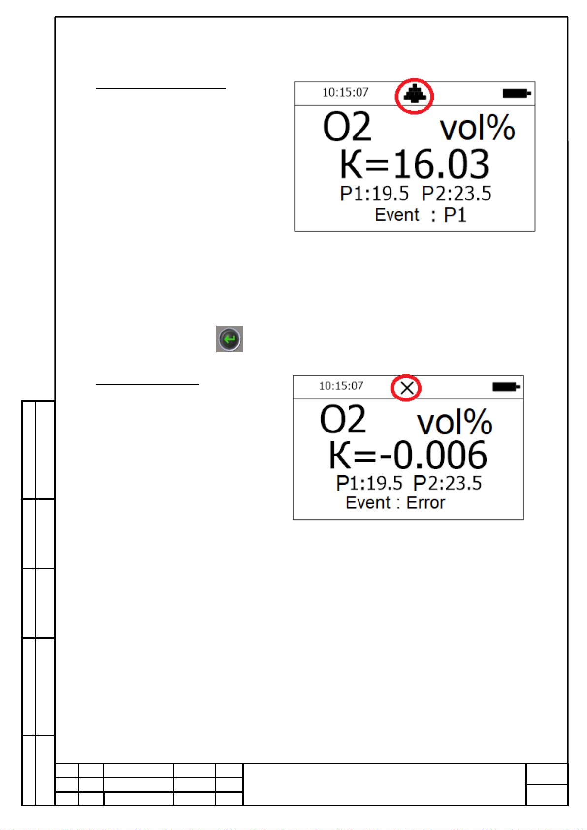
7. PGA-ESP detector operation
7.1. Alarm threshold exceeded.
When the alarm threshold is
exceeded, the light, sound, vibration alarms
are automatically turned on. The command
line displays Pictogram.
For the first threshold “Bell”, for the
second threshold “Three exclamation
points”.
The display automatically switches to a
single window of an activated alarm.
If the threshold is exceeded for more than 5
seconds, the threshold “clicks”. And until
the user manually resets the event message,
the alarm will remind him of it. There may
be several events. To return to standby
mode, the user must view all events. View
events by clicking the button
7.2. Internal malfunction
If there is an internal malfunction, the
“Cross” icon appears in the status bar.
And the message appears: “Event: error”

Orginal Inv
Signature and date
Instead of №
Conv. Inv. №
Signature and date
GSKF.002.025.100 OM
Sheet
20
Rev
.
Document №
Signature
Date
Sheet
8. Connection PGA-ESP to PC
Communication with a personal computer is carried out using the ESP-config program when
the device is placed in a USB adapter. To connect to a computer, a common micro-USB
connection cable is required.
The ESP-config software is designed to configure, check and calibrate the device at the
factory, as well as calibrate the device by the consumer.
Attention! Calibration of the device is allowed only outside the hazardous
area!
USB Adapter PGA-ESP
Micro-USB cable connector
Table of contents


