GasTech D-Guard2S User manual

t +61 8 6108 0000 e info@gastech.com w gastech.com
Digital Gas Detector with
Sounder Strobe
OPERATOR’S MANUAL
DS

D-Guard2
1
This Page Left Intentionally Blank

MANUAL ONVENTIONS.................................................................................................................................. 7
1.
WARNINGS, AUTIONS AND NOTES ....................................................................................................... 7
2.
LIMITATIONS OF USE .............................................................................................................................. 8
3.
PRODU T MARKINGS ............................................................................................................................. 9
4.
RE EIVING AND STORAGE .................................................................................................................... 10
4.1.
R
ECEIVING
................................................................................................................................................ 10
4.2.
I
NSPECTION
.............................................................................................................................................. 10
4.3.
S
TORAGE
.................................................................................................................................................. 10
5.
GASTE H AUSTRALIA ONTA T DETAILS .............................................................................................. 10
6.
GENERAL SAFETY PRA TI ES ................................................................................................................ 11
6.1.
R
ELEVANT
P
ERSONNEL
................................................................................................................................ 11
6.2.
S
AFETY
C
OMMUNICATION
........................................................................................................................... 11
6.3.
S
AFE
U
SE OF
E
QUIPMENT
............................................................................................................................ 11
6.4.
M
ODIFICATIONS TO
E
QUIPMENT
................................................................................................................... 11
6.5.
E
QUIPMENT
K
NOWLEDGE
............................................................................................................................ 11
7.
INTRODU TION .................................................................................................................................... 12
7.1.
P
URPOSE AND
C
ONTENTS
O
F
T
IS
M
ANUAL
................................................................................................... 12
7.2.
P
RODUCT
I
DENTIFICATION AND
T
YPE
............................................................................................................. 12
7.3.
C
ONTENTS
O
F
D-G
UARD
-2
P
ACKAGE
............................................................................................................ 13
........................................................................................................................................................................... 13
8.
PRODU T DES RIPTION ........................................................................................................................ 14
8.1.
P
RODUCT
F
UNCTION
.................................................................................................................................. 14
8.2.
D
ESCRIPTION
O
F
O
PERATION
....................................................................................................................... 14
9.
INSTALLATION ...................................................................................................................................... 15
9.1.
I
NSTALLATION
C
ONSIDERATIONS
................................................................................................................... 15
9.2.
G
ENERAL
I
NSTALLATION
P
RACTICES
............................................................................................................... 16
9.3.
D
ETECTOR
D
IMENSIONS AND
M
OUNTING
O
RIENTATION
................................................................................... 16
9.4.
I
NSTALLATION
C
ONSIDERATIONS
. .................................................................................................................. 17
9.4.1
Power supplies ................................................................................................................................... 17
9.4.2
Typical Connection to a power supply and controller ........................................................................ 17
9.4.3
Maintaining Correct Operating Conditions. ....................................................................................... 17
9.5.
M
OUNTING T E
E
NCLOSURE
........................................................................................................................ 18
9.5.1
Mounting Sur aces and Environment ................................................................................................ 18
9.5.2
Detector Location .............................................................................................................................. 19
9.6.
E
LECTRICAL
C
ONNECTIONS
.......................................................................................................................... 20
9.6.1
Field Terminal Access ......................................................................................................................... 20
9.6.2
Connection Details ............................................................................................................................. 21
9.6.3
Cable Entry and Connecting ............................................................................................................... 21
9.6.4
Conductor Preparation ...................................................................................................................... 22
9.6.5
Installation Cable Choice ................................................................................................................... 22
9.6.6
Cable Gland........................................................................................................................................ 23
9.6.7
Re itting The Detector Cover ............................................................................................................. 23
10.
OMMISSIONING ................................................................................................................................. 24
10.1.
I
NSTALLATION
V
ERIFICATION
........................................................................................................................ 24
10.2.
P
ERFORMANCE
C
ECKS
.............................................................................................................................. 25
10.3.
E
QUIPMENT
R
EQUIRED
F
OR
P
ERFORMANCE
C
ECKS
........................................................................................ 25
10.4.
B
UMP
T
EST
C
ONDITIONS
............................................................................................................................. 26
10.5.
B
UMP
T
EST
P
ROCEDURE
............................................................................................................................. 26
11.
DETE TOR OPERATING SYSTEM ............................................................................................................ 28
11.1.
D
ETECTOR
P
OWER
U
P
................................................................................................................................ 28

D-Guard2
1
11.2.
OME
S
CREEN
F
EATURES
............................................................................................................................ 29
11.2.1
User Menu status ........................................................................................................................... 29
11.3.
C
ONFIGURATION AND
C
ALIBRATION
M
ENU
N
AVIGATION
S
YSTEM
....................................................................... 30
11.3.1
So t-Key Functions and Icons .......................................................................................................... 30
11.3.2
Quick-Nav Function ........................................................................................................................ 31
11.3.3
Entering The Function Screens........................................................................................................ 31
12.
ALIBRATION ........................................................................................................................................ 32
12.1.
W
Y
C
ALIBRATE
? ..................................................................................................................................... 32
12.2.
P
REPARING FOR CALIBRATION
....................................................................................................................... 32
12.3.
Z
ERO
C
ALIBRATION
.................................................................................................................................... 33
12.3.1
Auto-Zero Calibration ..................................................................................................................... 33
12.3.2
Saving the Zero Calibration Value .................................................................................................. 34
12.3.3
Manual Zero Calibration ................................................................................................................. 34
12.3.4
Notes On Zero Calibration .............................................................................................................. 34
12.4.
S
PAN CALIBRATION
..................................................................................................................................... 34
12.4.1
Auto Span Calibration ..................................................................................................................... 35
12.4.2
Saving Auto-Span Calibration Values ............................................................................................. 36
12.4.3
Manual Span Calibration ................................................................................................................ 36
12.4.4
Per orming a Manual Span Calibration .......................................................................................... 36
12.4.5
Saving Manual Span Calibrations ................................................................................................... 36
12.4.6
Isolating the Detector During Span Calibration .............................................................................. 36
12.5.
C
URRENT
L
OOP
O
UTPUT
C
ALIBRATION
.......................................................................................................... 37
12.5.1
Setting the 4mA Output Current ..................................................................................................... 37
12.5.2
Setting the 20mA output Current ................................................................................................... 37
12.6.
D
YNAMIC
R
ESPONSE
T
IME
T
EST
F
UNCTION
..................................................................................................... 38
12.6.1
Running the DRT Checks ................................................................................................................. 38
13.
DETE TOR ONFIGURATION ................................................................................................................. 39
13.1.
S
ENSOR
C
ONFIGURATIONS
........................................................................................................................... 39
13.1.1
Set Guard Band ............................................................................................................................... 39
13.1.2
Set Measurement Full-Scale ........................................................................................................... 40
13.1.3
Detector Type ................................................................................................................................. 40
13.1.4
Setting Span Gas Concentration ..................................................................................................... 41
13.2.
A
LARM
C
ONFIGURATION
............................................................................................................................. 41
13.2.1
Making Alarm Con iguration Changes (Alarm 1 shown) ................................................................ 42
13.2.2
Alarm 1 Trip Level ........................................................................................................................... 42
13.2.3
Alarm 1 Hysteresis .......................................................................................................................... 42
13.2.4
Alarm 1 Trip Direction .................................................................................................................... 43
13.2.5
Alarm 1 Normal State ..................................................................................................................... 43
13.2.6
Alarm 1 Latching ............................................................................................................................ 43
13.2.7
Alarm 2 Current Settings Screen ..................................................................................................... 44
13.3.
D
IGITAL
D
ATA
C
ONFIGURATION
.................................................................................................................... 44
13.3.1
HART Setup Main Screen ................................................................................................................ 44
13.3.2
Turning HART Communications On or OFF ..................................................................................... 44
13.3.3
HART Tag data ................................................................................................................................ 45
13.3.4
HART Tag data – ixed loop mode .................................................................................................. 45
13.4.
S
YSTEM
C
ONFIGURATION
............................................................................................................................ 45
13.4.1
SYSTEM Setup Main Screen ............................................................................................................ 45
13.4.2
Turning Detector Isolation On or OFF ............................................................................................. 45
13.4.3
Internal Temperature Sensor .......................................................................................................... 46
13.4.4
Display Colour Invert ...................................................................................................................... 46
13.4.5
Sensor Temperature Compensation ............................................................................................... 46
13.4.6
Set Sensor Gain ............................................................................................................................................ 46
13.4.7
Set Menu Passcode ......................................................................................................................... 47
14.
DETE TOR MESSAGES AND WARNING STATES ..................................................................................... 47
14.1.
R
UNNING
I
NFORMATION AND
F
AULT
M
ESSAGES
.............................................................................................. 47
14.1.1
HART Communications Active ........................................................................................................ 47

D-Guard2
2
14.1.2
Detector Fault - Detector Over-Range ............................................................................................ 47
14.1.3
Detector Fault - Detector Under-Range .......................................................................................... 47
14.1.4
Detector Fault – Upper Operating Temperature ............................................................................ 48
14.1.5
Detector Fault – Lower Operating Temperature ............................................................................ 48
14.1.6
Detector Fault – Sensor Presence Failure ....................................................................................... 48
14.1.7
Detector Fault – Low Sensor Sensitivity .......................................................................................... 48
14.2.
F
AULT
L
OG
A
ND
I
NFORMATION
S
CREENS
....................................................................................................... 48
14.2.1
Detector Fault Log .......................................................................................................................... 48
14.2.2
Detector In ormation Screen .......................................................................................................... 48
14.2.3
Resetting the Detector Life Counter ............................................................................................................ 48
14.2.4
Calibration Fault ............................................................................................................................. 49
14.2.5
Internal Parameter Storage Fault ................................................................................................... 49
15.
ALARM INDI ATION.............................................................................................................................. 49
15.1.1
Warn Alarm Indication ................................................................................................................... 49
15.1.2
Danger Alarm Indication ................................................................................................................ 49
15.1.3
Latched Alarm Indication................................................................................................................ 49
15.1.4
Resetting From Alarm State ........................................................................................................... 49
15.1.5
Temporarily Silencing An Alarm ..................................................................................................... 50
15.1.6
Clearing An Alarm State ................................................................................................................. 50
16.
ONNE TING A HART FIELD OMMUNI ATOR ..................................................................................... 51
17.
DETE TOR MAINTENAN E .................................................................................................................... 52
17.1.
V
ISUAL
I
NSPECTION
.................................................................................................................................... 52
17.2.
ANDS
-O
N
(D
ETAILED
)
I
NSPECTIONS
............................................................................................................ 52
17.3.
G
AS SENSING CELL REPLACEMENT
.................................................................................................................. 53
17.3.1
Removing the Detector Main Board ............................................................................................... 53
17.3.2
Replacing the Sensor ...................................................................................................................... 53
17.4.
G
ENERAL
D
ETECTOR
R
EPAIR
........................................................................................................................ 54
17.5.
D
ISPOSAL OF
D-G
UARD
2
C
OMPONENTS
......................................................................................................... 54
18.
APPENDIX A: ......................................................................................................................................... 55
18.1.
O
UTPUT
C
URRENT
S
IGNAL
-
T
OTAL
L
OOP
R
ESISTANCE VS
P
OWER
S
UPPLY
V
OLTAGE
............................................... 55
18.1.1
Loop Resistance - D-Guard
2
With Backlight Disabled - loop at 22mA ............................................ 55
18.1.2
Loop Resistance - D-Guard
2
With Backlight Enabled - loop at 22mA ............................................. 55
19.
APPENDIX B: ......................................................................................................................................... 56
19.1.
R
ELAY
B
OARD AND
S
OUNDER
O
PTIONS
. ......................................................................................................... 56
19.1.1
Relay Board Functionality ............................................................................................................... 56
19.1.2
Table o Functions (identi ied by silk screen legend on relay board and photo annotations) ........ 57
19.2.
R
ELAY
B
OARD
C
ONNECTIONS
....................................................................................................................... 58
19.2.1
Current Loop Connection Scheme ................................................................................................... 58
19.2.2
Stand-Alone Connection Scheme .................................................................................................... 58
20.
APPENDIX : ......................................................................................................................................... 59
20.1.
D
ISABLING T E
D
ISPLAY
B
ACKLIG T
.............................................................................................................. 59
21.
APPENDIX D: ......................................................................................................................................... 60
21.1.
C EMICAL
COMPATIBILITY ................................................................................................................... 60
22.
APPENDIX E: ......................................................................................................................................... 61
22.1.
C
ROSS
S
ENSITIVITY
-
T
OXIC
S
ENSORS
............................................................................................................. 61
22.2.
C
ROSS
S
ENSITIVITY
-
I
NFRA
-R
ED
S
ENSORS
...................................................................................................... 61
23.
APPENDIX F: ......................................................................................................................................... 62
23.1.
E
NVIRONMENTAL
E
FFECTS ON
D
ETECTOR
P
ERFORMANCE
.................................................................................. 62
23.2.
T
EMPERATURE
.......................................................................................................................................... 62
23.3.
P
RESSURE
................................................................................................................................................. 62
23.4.
UMIDITY
................................................................................................................................................ 62

D-Guard2
3
24.
APPENDIX G: ......................................................................................................................................... 63
24.1.
S
YSTEM
M
ENU
M
AP
.................................................................................................................................. 63
25.
APPENDIX H: ......................................................................................................................................... 64
25.1.
P
ERFORMANCE
S
PECIFICATIONS
.................................................................................................................... 64
25.1.1
General Speci ications .................................................................................................................... 64
25.1.2
Methane Detector Speci ications ................................................................................................... 64
25.1.3
Carbon Dioxide Detector Speci ications .......................................................................................... 65
25.1.4
Electro-Chemical Detector Speci ications ....................................................................................... 65
25.1.5
Mechanical & Environmental Speci ications .................................................................................. 65

D-Guard2
4
PROPRIETARY STATEMENT
Gastech owns proprietary rights in the information disclosed within. By receiving this document, the recipient
agrees that neither this document nor the information disclosed within nor any part shall be reproduced or
transferred to other documents or used or disclosed to others for manufacturing or for any other purpose except
as specifically authorised in writing by Gastech.
COPYRIGHT NOTICE
© 2014 - All rights reserved.
Information contained in this document is protected by copyright. No part of this document may be
photocopied, reproduced, or translated to another program or system without prior written authorisation from
Gastech.
TRADEMARK STATEMENT
Protected through use and/or registration in the United States and many foreign countries are the trademarks
and service marks of Gastech. The use of the ® symbol indicates registration in the United States only and the
“
TM
” is in Australia; registrations may not have been issued at present in other countries. All other product names
and logos are trademarks of their respective owners.
DISCLAIMER
Under no circumstances will Gastech be liable for any claims, losses, or damages resulting from, or arising out
of, the repair of, or modification to the equipment by a party other than Gastech or its authorised service
representatives, or by operation or use of the equipment other than in accordance with the printed instructions
provided by Gastech or if the equipment has been improperly maintained or subject to neglect or accident. Any
of the foregoing will void the warranty.
REVISIONS TO MANUAL
While every effort has been made to assure the accuracy and clarity of this document, Gastech assumes no
liability resulting from any omissions in this document, or from misuse of the information obtained herein. The
information in this document has been carefully checked and is believed to be entirely reliable with all of the
necessary information included. Gastech reserves the right to make changes to any products described herein
for the purposes of improved reliability, functionality, or design, and reserves the right to revise this document
and make changes to its content as may become necessary with no obligation to notify any persons of revisions
or changes.

D-Guard2
5
SERVICE POLICY
Gastech maintains an instrument service facility at the factory as well as authorised service facilities around the
world. Should your instrument require service, you may contact us toll free at 1800 999 902 within Australia
only or 61-8-6108-0000, or visit our website www.gastech.com for authorised service locations.
For non-warranty repairs, you will need to provide a purchase order number. If you need to set a limit to the
repairs costs, state a “Not to Exceed” figure. If you need a quotation before you can authorise repair costs, so
state, but understand this will incur additional costs and may delay processing of the repair.
If you wish to set a limit to the authorised repair cost, state a “not to exceed” figure. Gastech’s policy is to
perform all needed repairs to restore the instrument to full operating condition, including reactivation or
replacement of all out-of-warranty electrochemical cells.
You may send the unit, freight prepaid, to: Gastech Pty Ltd, 24 Baretta Rd, Wangara, Western Australia WA 6065.
Attn.: Service Department. Enclose the copy of your contact details. Pack the instrument and all its accessories
(preferably in its original packing) and any special instructions. Repairs are warranted for 90 days from the date
of shipment. Sensors have individual warranties.
Always include your address, purchase order number, shipping and billing information, and a description of the
defect as you perceive it. If this is the first time you are dealing directly with the factory, you will be asked to
provide credit references, prepay, or authorise COD shipment.
NOTE: Gastech assumes no liability for work performed by unauthorised service facilities.

D-Guard2
6
WARRANTY STATEMENT
1. Consumers have the benefit of conditions and warranties implied by the Trade Practices Act 1974 (TPA) and
similar provisions of State and Territory enactments and nothing in these conditions is intended to exclude,
restrict or modify any statutory obligation of GASTEC PTY LTD (Company) if that cannot lawfully be
effected.
2. This warranty relates only to Equipment manufactured and services supplied by the Company, its related
corporations and subsidiaries. Equipment or any part thereof which is returned to the Company,
transportation prepaid, within 15 months from the date of dispatch from the Company’s premises or 12
months from the date of shipment to the ultimate user (whichever occurs first) and is found by the
Company, after examination, to be defective in workmanship or materials, will be either repaired or
replaced as determined by the Company, free of charge. The terms of this paragraph apply unless stated
otherwise in this instruction manual.
3. This warranty does not apply to:
a) replacement or repairs which are required as a results of improper installation, misuse,
maladjustment modification or lack of routine maintenance by others;
b) items subject to deterioration or consumption in normal service, that is, those which must be
cleaned, repaired or replaced routinely such as (but not limited to) lamps, bulbs and fuses, pump
diaphragms and valves, absorbent cartridges, filter elements and batteries; or
c) goods, materials or parts supplied or manufactured by unrelated third parties and provided to the
Purchaser at the specific request of the Purchaser and such goods, materials or parts will be
repaired or replaced only to the extent of the original suppliers warranty.
4. Should the Company be liable for breach of a condition or warranty (other than the pursuant to section 69
of the TPA) implied by Division 2 of Part V of the Act (other than that implied by section 69 of the TPA) the
liability of the Company for such breach shall, subject to section 68A(2) of the TPA, be limited to one of the
following as determined by the Company.
a) the replacement of the Equipment or the supply of equivalent Equipment-,
b) the payment of the cost of replacing the Equipment or of acquiring equivalent Equipment.
5. Subject to Clauses 2 and 4 and any legislation to the contrary:
a) representatives and agreements not expressly contained herein shall not be binding upon the
Company as conditions, warranties or representations; all such conditions, warranties, and
representations on the part of the Company, whether express or implied, statutory or otherwise,
whether collateral or antecedent or otherwise are hereby expressly negatived and excluded;
b) the Company shall be under no liability to the Purchaser for any loss (including but not limited to
loss of profits and consequential loss) or for damage to persons or property or for death or injury
caused by any act or omission (including negligent acts or omissions) of the Company or the
Company’s agents, wherever occurring, arising from the subject matter of this agreement;
c) the Purchaser shall indemnify the Company against any claims made against the Company by any
third party in respect of any such loss, damage, death or injury as is set out in sub-paragraph b)
hereof; the Purchaser further agrees to indemnify the Company against all losses and expenses
which the Company may suffer or incur due to the failure of the Purchaser fully to observe its
obligations under this contract; and
d) no warranty is given and no responsibility is accepted by the Company to ensure the Equipment
supplied complies with any statutory requirements relating to the marketing of goods. Compliance
with such legislation shall be the sole responsibility of the Purchaser.
e) the Company specifically denies any liability for the overall performance of any plant or the results
of any process with which the Equipment is integrated.

D-Guard2
7
Manual onventions
D-Guard
2
is designed to detect, depending upon which sensor type is fitted, flammable gases and vapours,
oxygen concentration or toxic gases. The detector is intended to signal one or more warnings before gas
concentrations reach dangerous or harmful levels.
In order to ensure that the detector's intended function will operate as designed, it is essential that the
information and instructions presented in this manual are read and understood prior to installing, using or
maintaining the equipment. In particular, a thorough understanding of the information relating to
configuration, operation, calibration, and maintenance is essential before using D-Guard
2
.
To aid with the process of bringing attention to key points, graphical notices are used in this manual. These
notices are graded based upon the consequence of ignoring or incorrectly applying the information given.
Warning. Significant risk to health and safety with the possibility of serious injury or death.
aution. Possibility of unsafe operation of D-Guard
2
and connected equipment.
Warranty of D-Guard
2
and connected equipment may be invalidated.
Note. Additional information is provided to assist with understanding of detector
operation, configuration, calibration or maintenance.
1. Warnings, autions and Notes
For safety reasons, D-Guard
2
must be installed, operated and serviced only by competent and appropriately
trained personnel. Reading and understand this instruction manual completely is essential before installing,
operating or servicing this equipment. Failure to install or operate this instrument in accordance with
instructions contained in this manual may result in invalidation of the conditions of warranty and additionally
create hazardous operating conditions.

D-Guard2
8
2. Limitations of Use
D-Guard
2
G, D-Guard
2
R and D-Guard
2
S Detectors:-
Can NOT be used in Group I hazardous area applications.
Can NOT be used in Group IIC hazardous area applications.
Can NOT be used in Group IIB hazardous area applications.
Can be used in conjunction with other equipment as part of a safety instrumented system for the
purposes of risk reduction.
The detector is NOT designed to be used as the sole means of ensuring safety to personnel or
equipment.
Must not be used in an oxygen enriched atmosphere.
Must not be modified in any manner*. As supplied, the unit is constructed in accordance with, and is
compliant with the quality and performance standards against which it has been designed and tested.
Modification to its construction will invalidate the product's warranty.
Is not on-site repairable and contains no user serviceable parts (sensors and filter excepted).

D-Guard2
9
3. Product Markings
The D-Guard
2
G,
D-Guard
2
R and D-Guard
2
S Gas detectors are designed for use in general purpose non-certified
applications only. Their suitability for use in any particular application depends on the product variant and the
sensor type fitted.
The detectors carry the following information as part of its serial number identification label:
These makings provide information identifying the gas type, serial number and its IP rating.
Label Details (model number and IP rating) will vary depending upon the model type.
65-1080G-xxx: Base model. IP66/67/68.
65-1080R-xxx: Relay option fitted. IP66/67/68.
65-1080S-xxx, Relay and Sounder/Strobe fitted. IP65.

D-Guard2
10
4. RE EIVING AND STORAGE
4.1. Receiving
All possible precautions are taken to protect the equipment against damage or losses during shipment to our
customers, however before accepting delivery, it is strongly recommended that a check of all received items is
made against the packing list or billing of lading. If there is a shortage or evidence of physical damage, notify
Gastech immediately.
Notify Gastech within 7 days (maximum) in case of shortage or discrepancies, according to the packing list. This
will assist in a speedy resolution to problems. Please keep a record of all claims and correspondence. Where
possible, taking and supplying photographs is advantageous.
Where practicable do not remove protective covers prior to installation unless there are indications of damage
that necessitate closer inspection. Packaging that has been opened for inspection and inventory logging should
be carefully repacked to ensure protection of contents or else the parts should be packaged and stored in a safe
place. Examine all shipping boxes, and protective packaging for items attached to them, especially if the
wrapping are to be discarded.
4.2. Inspection
Equipment that is found to be damaged or appears to have been modified in any manner must not be used.
Please contact Gastech if the equipment is suspected to be different than that ordered or if it does not match
the published specifications.
4.3. Storage
Where equipment is not going to be installed immediately, proper storage is important to ensure protection
against damage. Damage incurred during storage could render the equipment non-functional.
Electro-Chemical gas sensing cells (used in this equipment), have a maximum ‘shelf’ life of 6 months
from the date of shipment by Gastech. If equipment is stored for periods longer than this, the
performance of the gas sensing cell cannot be guaranteed by Gastech.
All equipment should be stored indoors in a cool dry location, protected from adverse environmental elements.
If storing at ground level, ensure that the storage area is not an area where water will collect.
5. Gastech ontact Details
Head Office
24, Baretta Rd,
Wangara, Western Australia 6065
Int. Phone: +61 8 6108 0000
Int. Fax: +61 8 9408 1868

D-Guard2
11
6. GENERAL SAFETY PRA TI ES
6.1. Relevant Personnel
Ensure all personnel directly responsible or involved with installation, operation and maintenance of the
equipment make reference to this manual in conjunction with any relevant risk assessments conducted to
identify and minimise potential hazards.
6.2. Safety ommunication
All safety instructions, usage conditions and restrictions given within this manual must be communicated to all
users. These requirements are necessary to identify and control potential risk associated with possible misuse
or incorrect application of this piece of equipment. In the event of damage or malfunction to the detector that
results in the potential to compromise the health and safety of any personnel, the owner/operator should notify
the manufacturer immediately.
6.3. Safe Use of Equipment
Equipment as supplied has been manufactured within the controls of relevant International and/or Australian
Standards and state legislative requirements. Equipment identified within this manual has been designed for a
specific purpose, therefore any modification or damage to it must be reported to the manufacturer to allow for
repair or replacement.
The instructions within this manual must be observed as an aid towards achieving maximum safety during
operation.
6.4. Modifications to Equipment
Modifications to the design or construction of this equipment is not permitted under the conditions
of its warranty.
6.5. Equipment Knowledge
Experience in the use of, and a technical understanding of this equipment is essential for its safe installation,
operation, maintenance and removal from an application. If in doubt, seek advice from a supervisor and/or
contact Gastech immediately.
Mechanical, electrical installation and maintenance of plant and equipment, must only be carried out by
appropriately, trained, qualified and competent personnel.

D-Guard2
12
7. INTRODU TION
7.1. Purpose and ontents Of This Manual
This manual contains installation, operating and maintenance instructions for the Gastech D-Guard
2
R and D-
Guard
2
S current loop / 3 wire powered, Smart Gas Detectors. Users of this equipment must read and understand
the contents of this manual in order to ensure safe use and optimum performance from the product.
7.2. Product Identification and Type
The products are named D-Guard
2
R and D-Guard
2
S. The products classification are either as loop-powered toxic
and flammable gas detectors (no relays or sounder), or as 3-wire connected toxic and flammable gas detectors
when fitted with either the relay option (R version) or both relay and sounder (S version).
Individual detectors are identified by a unique serial number located on the product identification plate fixed to
the side of the enclosure. Reference to this label is important to correctly identify the product build and gas
type. Detectors must only be used in applications for which they are compatible.
D-Guard
2
R and D-Guard
2
S are non-Ex certified detectors and MUST NOT be used in applications requiring
explosion protected Ex certified equip ent.
The gas type and range detectable by the unit are set by the combination of an appropriate sensor type being
installed and by configuration via the set-up menus. However - for the product to remain compliant with its
warranty, end users are NOT permitted to change the gas type measured by substitution of sensor type. This is
only permitted to be carried out by Gastech or an approved Gastech representative.
If changes to the gas sensor type are carried out by the end user, product warranty will be
invalidated.
End users may change the gas measurement range and displayed gas name via the configuration
menus and / or ART communications, however Gastech will not accept responsibility for, nor accept
liability for damage or injury caused by instruments rendered unsuitable for any particular application
following such changes. The facility for configuring the detector from within its operating system is
primarily intended for use by GasTech appointed distributors and service teams.
The following table specifies the default 'as-supplied' product variations.
Gas Type
Full Scale Range
Gastech
Part No.
Base Models
Optional Relays Fitted
Relays and sounder/strobe fitted
Ammonia
0
-
100ppm
65
-
1080
G
-
N 3
65
-
1080
R
-
N 3
65
-
1080
S
-
N 3
Carbon
Monoxide
0
-
1000ppm
65
-
1080
G
-
CO
65
-
1080
R
-
CO
65
-
1080
S
-
CO
Chlorine
0
-
10ppm
65
-
1080
G
-
CL2
65
-
1080
R
-
CL2
65
-
1080
S
-
CL2
Ethylene Oxide
0
-
20ppm
65
-
1080
G
-
ETO
65
-
1080
R
-
ETO
65
-
1080
S
-
ETO
Fluorine
0
-
1ppm
65
-
1080
G
-
F2
65
-
1080
R
-
F2
65
-
1080
S
-
F2
ydrogen Chloride
0
-
100ppm
65
-
1080
G
-
CL
65
-
1080
R
-
CL
65
-
1080
S
-
CL
ydrogen Cyanide
0
-
50ppm
65
-
1080
G
-
CN
65
-
1080
R
-
CN
65
-
1080
S
-
CN
ydrogen Sulphide
0
-
200ppm
65
-
1080
G
-
2S
65
-
1080
R
-
2S
65
-
1080
S
-
2S
Nitrogen Dioxide
0
-
10ppm
65
-
1080
G
-
NO2
65
-
1080
R
-
NO2
65
-
1080
S
-
NO2
Nitric Oxide
0
-
100ppm
65
-
1080
G
-
NO
65
-
1080
R
-
NO
65
-
1080
S
-
NO
Ozone
0
-
2ppm
65
-
1080
G
-
O3
65
-
1080
R
-
O3
65
-
1080
S
-
O3
Phosphine
0
-
1ppm
65
-
1080
G
-
P 3
65
-
1080
R
-
P 3
65
-
1080
S
-
P 3
Sulphur Dioxide
0
-
10ppm
65
-
1080
G
-
SO2
65
-
1080
R
-
SO2
65
-
1080
S
-
SO2
Oxygen
0
-
25%
volume
65
-
1080
G
-
O2
65
-
1080
R
-
O2
65
-
1080
S
-
O2
Methane
0
-
5% v/v
65
-
1080
G
-
LEL
65
-
1080
R
-
LEL
65
-
1080
S
-
LEL
Methane
0
-
100% v/v
/ LEL
65
-
1080
G
-
C 4
65
-
1080
R
-
C 4
65
-
1080
S
-
C 4
Carbon Dioxide
0
–
1.
5% v/v
65
-
1080
G
-
CO2
65
-
1080
R
-
CO2
65
-
1080
S
-
CO2
Client Specified
*
x
xx = gas typ
e/range
6
5
-
1080
G
-
xxx
65
-
1080
R
-
xxx
65
-
1080
S
-
xxx
*
Toxic gas types only
Table 1: Standard/ ustom Gas Types and Ranges covered by the D-Guard
2
G, D-Guard
2
R and D-Guard
2
S
ranges.

D-Guard2
13
7.3. ontents Of D-Guard-2 Package
The shipment package for an individual D-Guard
2
should contain the following components:
Gas Detector assembly.
User Manual.
Combined enclosure / splashguard key and calibration magnet.
Manufacturing Quality certificate.
If the received package is incomplete, please contact Gastech or the distributor that supplied the product.
Refer to Section 4 for unpacking and storage information.

D-Guard2
14
8. PRODU T DES RIPTION
8.1. Product Function
The D-Guard
2
smart Gas detector’s function is to detect the presence of gas (or reduction in oxygen
concentration) in the environment immediately surrounding it. Such gases may be toxic, flammable or
asphyxiant, where concentrations may exceed safe exposure limits for occupants or combust in the presence
of ignition sources. The D-Guard
2
detector range is designed to connect to other equipment or systems that are
responsible for activating ventilation and/or sounding alarms to mitigate the risks associated with the presence
of increased concentrations of gases or low levels of breathable oxygen.
8.2. Description Of Operation
The D-Guard
2
smart gas detectors are designed to sense gases that enter them via the process of natural
diffusion through the gas entry port.
The sensor type used within the D-Guard
2
to detect the gas is dependent upon the specific characteristics of the
gas needing to be monitored. If the gases to be monitored pose a risk of being toxic, then a D-Guard
2
with
electro-chemical type cells must be used. With the exception of hydrogen, if the reason for monitoring gas is
due to the risk of ignition, then a D-Guard
2
fitted with Infra-Red sensors should be used. For detection of
hydrogen, a D-Guard
2
with an electro-chemical cell should be used. For monitoring oxygen levels for depletion,
a D-Guard
2
with an oxygen sensor must be used.
In any environment, gases released into an open space will spread-out (diffuse) to equally occupy the volume
of space available. The diffusion of gases occurs due to mechanisms such as natural or forced air currents as
well as molecular collisions.
Whether the space into which gas is released is totally empty of any gas molecules, or already contains gas
molecules (e.g. air), the molar concentration (a measure of the actual number of gas molecules) or the
volumetric concentration (a measure of relative amounts of each gas component in a mixture) of a gas at any
given location and time will relate to its concentration at the point of release, the volume of space into which it
expands and influences such as ventilation that affect the rate at which diffusion occurs. In most cases, over a
long enough time, the concentration of gas anywhere within the space will have equal concentration. owever,
in areas with enclosed spaces with poor ventilation, gas may 'pool' in higher concentrations if the rate of gas
leakage into the space is greater than the rate of diffusion out of it. Pooling can occur in roof spaces for gases
that are less dense than air or in pits and tunnels for gases that are more dense than air.
The various diffusion processes are the mechanism by which gas enters the D-Guard
2
in order to be detected.
Gas molecules will diffuse through the gas-permeable waterproof membrane and into the sensor body, where
they react with specific sensor mechanisms to produce signals proportional to the gas concentration.
For toxic gases entering electro-chemical sensors, an electrical current proportional to concentration will be
produced. For flammable gas molecules entering an infra-red sensor, infra-red energy will be absorbed
proportionate to gas concentration. This absorption is processed to produce a concentration related signal.
Signals from the various sensor types feed into the detectors electronics and signal processing software where
they are converted to scaled values and used for display indication, concentration and alarm signalling.
D-Guard
2
signals gas concentration to remotely connected equipment via its two power supply connections. It
does this by varying the amount of current it draws from the power supply in direct proportion to the gas
concentration measured. This is generally referred to as 'current loop signalling' and commonly uses 4mA to
represent zero gas conditions and 20mA to indicate full scale. D-guard
2
can also signal gas concentrations, along
with other data using a digital communications system called ' ART' ( ighway Addressable Remote
Transducer/Transmitter). This digital signal is super-imposed onto the current loop 4-20mA signal. Additionally,
D-Guard
2
can (optionally) provide volt-free relay contacts that can be programmed to respond at user-set gas
concentrations. Gas concentration values and other information is also presented on the display for localised
reading. Sensor operating errors are also signalled via a current loop level above or below the normal 4-20mA
range.

D-Guard2
15
9. INSTALLATION
9.1. Installation onsiderations
The D-Guard
2
Toxic Gas detector would generally be part of a larger system and be connected to other
components or equipment within it. These other pieces of equipment would generally provide the function of
signal acquisition, decision making, shutdown, control and indication (PLC's, fan controls, beacons, sirens, SCADA
systems etc.). D-Guard
2
can also be used as a standalone instrument as part of a 'mini system' using alarm type
devices connected directly to its relay terminals.
Whichever type of system D-Guard
2
is intended to be used in, before the detector can be installed, there are a
number of things that need to be considered to prevent incorrect or unsafe operation of both the detector and
the system into which it is installed. Along with relevant competence, and an understanding of the target
application, the following points should be considered:-
Ensure that the information provided in sections 1 to 6 is fully understood.
It is extremely important that the li itations and restrictions for use o the detector are understood in order to
prevent the creation o hazardous situations and increased risk o dangerous events occurring . I in doubt as to
the nature o these limitations/restrictions, or their implication, consult a competent authority such as a
supervisor or Gastech applications engineer.
Ensure that the information in sections 11 to 19, plus Appendix A are understood.
It is extremely important that the functionality o the detector is ully understood in order to reduce the likelihood
o creating hazardous situations and risks due to a mal unctioning detector or gas monitoring system. I in doubt
as to the unctionality o the detector, or the implications o incorrect use, consult a competent authority such as
a supervisor or Gastech applications engineer.
Ensure that the application into which the detector is to be installed is correctly understood.
Any system intended to mitigate the risk o injury needs to be properly designed and implemented. Such a system
must be the result o structured risk analysis with the outcomes used to help de ine the sa ety system
requirements. Such risk assessments will take into considerations the nature o the application along with its
processes and likely hazards. The sa ety system requirements, in turn, will guide the choice o instrumentation,
logic solvers and actuators needed to implement the system. Understanding the required unctionality o the
system will ensure proper selection and sa e deployment o equipment.
Ensure that the detector will properly perform the required functions within the system design.
It is important to understand how the detector will interact with other equipment within a system. For sa e and
reliable use, it is crucial that neither the detector or other system components signalling be compromised by
incompatibilities between equipment.

D-Guard2
16
9.2. General Installation Practices
Before starting the installation process, read this operational manual thoroughly, making particular note to any
aspects that could affect the reliability or accuracy of D-Guard
2
. It is essential that the operational specifications
for the instrument are understood in relation to compatibility with the rest of the system.
Refer to Appendix C for infor ation regarding sensor basics, che ical co patibility and cross-sensitivity.
D-Guard
2
should be installed in a location allowing easy access for repairs, adjustments and
calibration. The mounting position must allow visibility of the identification plate.
Mount the instrument in a position that will minimise the risk of mechanical damage.
Ensure that the gas entry port is clear of obstruction which would prevent the passage of gas into the
internal detector cell.
Prevent water and dust accumulation from affecting operation by mounting the sensor unit with the
gas entry port pointing forwards or downward. Do not install the instrument with the gas entry port
facing upwards as this may allow the collection of water or dust to prevent gas entering the sensor.
Do not leave the splash-guard unfitted as this will allow water and dust to collect directly on the
sensor surface filter.
It is important to ensure that any cable entry points to the enclosure are watertight by properly
tightening up the cable entry grip.
If cable glands are to be substituted, they must be replaced by types suitable compatible types and
must be both IP66 and IP68 ingress protected to maintain the detectors overall IP rating.
9.3. Detector Dimensions and Mounting Orientation
Ideal position Operationally acceptable positions (although the display is difficult to read)
(Recommended)
Do NOT Mount this way

D-Guard2
17
9.4. Installation onsiderations.
The connections between D-Guard
2
and other interconnected equipment must be compatible in terms of
voltages, power capabilities and input resistances if the detector is to function correctly.
Particular attention should be paid to the minimum and maximum voltage output from any power source since
the ability for the detector to properly signal measured gas concentrations will depend on correctly chosen
power supplies.
9.4.1 Power supplies
If the power supply voltage is too great, there is a risk of damaging the detector. Power supply voltages that are
too low at the detector input terminals may prevent the full 3.3mA – 22mA signalling range being available at
the system controller input.
9.4.2 Typical onnection to a power supply and controller
Power supply Sensor Controller
9.4.3 Maintaining orrect Operating onditions.
When handling the D-Guard
2
during installation, great care must be taken to not damage any part of the system
components, since this may compromise its functionality.
Damage caused by mishandling or by connection to incompatible equipment could render inoperative, those
aspects of the detector that product correct operation and safety rely on.
If any damage is evident to any part of the detector electronics or enclosure system, it must not be used.
If such damage is present, advice from Gastech should be sought to remedy the problem before proceeding.
Table of contents
Other GasTech Gas Detector manuals
GasTech
GasTech GTD2000-Tx User manual

GasTech
GasTech D-Guard2 User manual

GasTech
GasTech F-Guard-UV-IR-HD User manual

GasTech
GasTech F-GUARD UVIR User manual

GasTech
GasTech Cannonball 3 User manual
GasTech
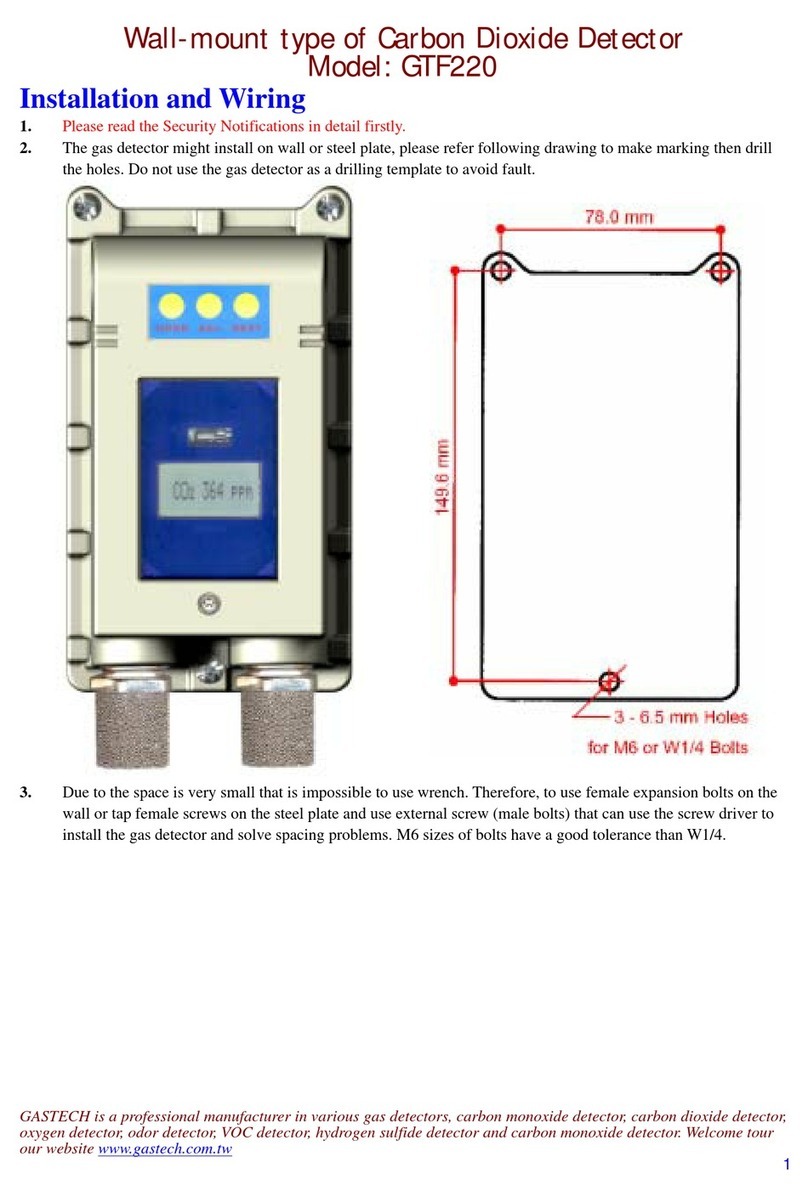
GasTech GTF220 User manual

GasTech
GasTech F-Guard-IR3-H2 User manual

GasTech
GasTech D-Guard2 User manual

GasTech
GasTech G-Shield Fire User manual
GasTech
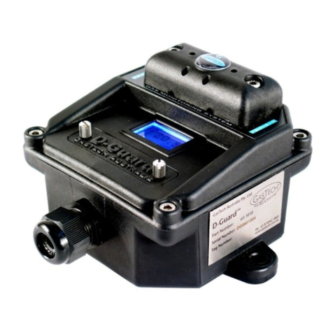
GasTech D-Guard User manual
Popular Gas Detector manuals by other brands

Medem
Medem SEC-K V4 installation instructions
Zehnder Rittling
Zehnder Rittling CO2 Sensor Manual for the user

sewerin
sewerin EX-TEC SR5 operating instructions

SENSIT Technologies
SENSIT Technologies VMD Set-up & operating instructions
Evikon
Evikon PluraSens E2658 Series user manual

Detcon
Detcon DM-700 Safety manual
