Rietschle PICOLINO DTE Series User manual

DTE
DTE 8
(50), (51), (52)
B
Q
N
d
A
P O J
Betriebsanleitung
Verdichter
Ausführungen
DieseBetriebsanleitunggiltfürfolgendentrockenlaufenden
Drehschieber-Verdichter: DTE 8 (50), (51), (52)
Die DTE 8 hat einen Volumenstrom von 8 m3/h. Der Über-
druck beträgt 0,4 bar bei S1 und 0,8 bar bei S3 60%.
Beschreibung
Motor und Verdichter haben eine gemeinsame Welle. Die
Varianten (50), (51), (52) der DTE unterscheiden sich
durch verschiedene Anschlußsteckverbindungen (J).
Der Antrieb erfolgt durch einen Gleichstrommotor.
Verwendung
Die Verdichter DTE sind für den Einsatz im ge-
werblichen Bereich geeignet, d.h. die Schutzein-
richtungen entsprechen EN DIN 294 Tabelle 4 für Per-
sonen ab 14 Jahren.
Die DTE eignet sich zur Erzeugung von Überdruck zwi-
schen 0 und der auf dem Datenschild (N) angegebenen
Höchstgrenze (bar). Dauerbetrieb ist zulässig.
Die Umgebungstemperatur und die Ansaug-
temperatur muß zwischen -25 und +50°C liegen. Bei Temperaturen außerhalb dieses Bereiches bitten wir
um Rücksprache.
Diese trockenlaufenden Verdichter eignen sich zum Fördern von Luft mit einer relativen Feuchte von 30 bis 100%.
Es dürfen keine gefährlichen Beimengungen (z.B. brennbare oder explosive Gase oder Dämpfe), Wasser-
dampf, aggressive Gase oder Spuren von Öl, Öldunst und Fett angesaugt werden.
Die Standard-Ausführungen dürfen nicht in explosionsgefährdeten Räumen betrieben werden.
Bei Anwendungsfällen, wo ein unbeabsichtigtes Abstellen oder ein Ausfall des Verdichters zu einer
Gefährdung von Personen oder Einrichtungen führt, sind entsprechende Sicherheitsmaßnahmen anla-
genseits vorzusehen.
Handhabung und Aufstellung
Bei betriebswarmem Verdichter können bei der DTE 8 die Oberflächentemperaturen an den Bauteilen (Q)
über 70°C ansteigen. Dort ist eine Berührung zu vermeiden.
Zum Demontieren des Gehäusedeckels (d) müssen für Wartungsarbeiten mindestens 20 cm Platz vorhanden sein.
Die DTE können in horizontaler Einbaulage fehlerfrei betrieben werden. Andere Einbaulagen auf Anfrage.
Bei Aufstellung höher als 1000 m über dem Meeresspiegel macht sich eine Leistungsminderung bemerk-
bar. In diesem Fall bitten wir um Rücksprache.
Die Aufstellung der Verdichter auf festem Untergrund ist ohne Verankerung möglich. Bei Aufstellung auf einer
Unterkonstruktion empfehlen wir eine Befestigung über elastische Pufferelemente. Die Vibrationen dieser Dreh-
schieber-Verdichter sind sehr gering.
Installation (Bild und )
Bei Aufstellung und Betrieb ist die Unfallverhütungsvorschrift »Verdichter« VBG 16 zu beachten.
1.Druckanschluß bei (B).
Bei zu enger und/oder langer Druckleitung vermindert sich der Volumenstrom des Verdichters.
2.DieelektrischenMotordatensindaufdemMotordatenschild (P)angegeben. DieMotorenentsprechenDIN/VDE 0530
und sind in Schutzart IP 65 und Isolationsklasse F ausgeführt. Die Motordaten sind mit den Daten des vorhandenen
Stromnetzes zu vergleichen (Stromart, Spannung, Polarität, zulässige Stromstärke).
3.Motor über Stecker-Anschluß (J) anschließen (Steckerbelegung siehe Datenblatt 961271 bzw. 961272).
Die elektrische Installation darf nur von einer Elektrofachkraft unter Einhaltung der EN 60204 vorgenom-
men werden. Der Hauptschalter muß durch den Betreiber vorgesehen werden.
B 387/50
1.11.99
Werner Rietschle
GmbH + Co. KG
Postfach 1260
79642 SCHOPFHEIM
GERMANY
07622 / 392-0
Fax 07622 / 392300
E-Mail: [email protected]
http://www.rietschle.com

/ PM6
e d s
ZY
X
O
1
DTE 8 (50) (51) (52)
dB(A) 65
kg 9
mm 240 278 278
mm 128
mm 119
1.2001
Schalldruckpegel (max.)
Gewicht
Länge
Breite
Höhe
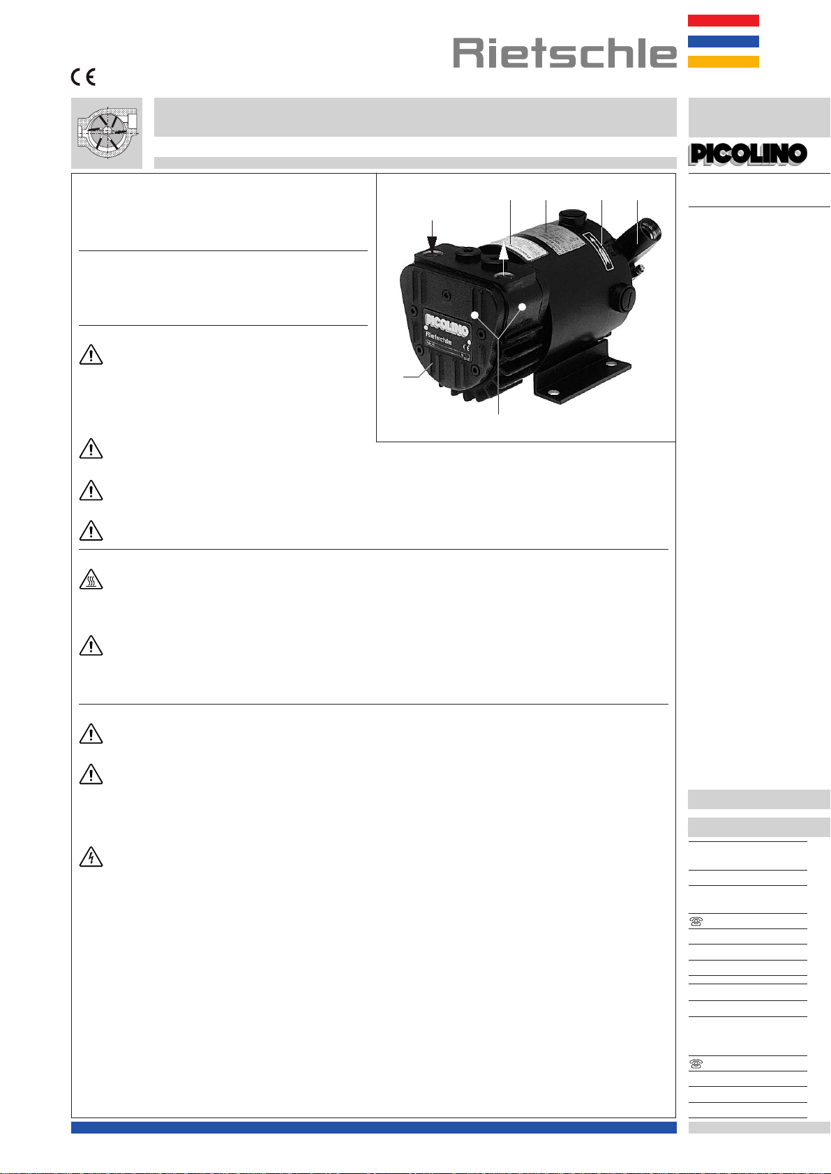
Inbetriebnahme (Bild )
1. Motor zur Drehrichtungsprüfung kurz starten. Bei richtiger
Drehrichtung tritt am Druckanschluß (B) Luft aus.
Achtung! Druckanschlußmußoffensein,sonstkönnen
bei falscher Drehrichtung die Lamellen brechen.
2.Druckleitung an (B) anschließen.
Wartung und Instandhaltung
BeiWartungsmaßnahmen,beidenenPersonendurch
bewegte oder spannungsführende Teile gefährdet
werden können, ist der Verdichter nach Freischalten und
ZiehendesSteckersvomVersorgungsnetzzutrennenund
gegen Wiedereinschalten zu sichern.
Wartung nicht bei betriebswarmem Verdichter durchfüh-
ren. (Verletzungsgefahr durch heiße Maschinenteile).
1. Schmierung DieDTE hat eineDauerfettschmierung für die
Lager und braucht nicht nachgeschmiert zu werden.
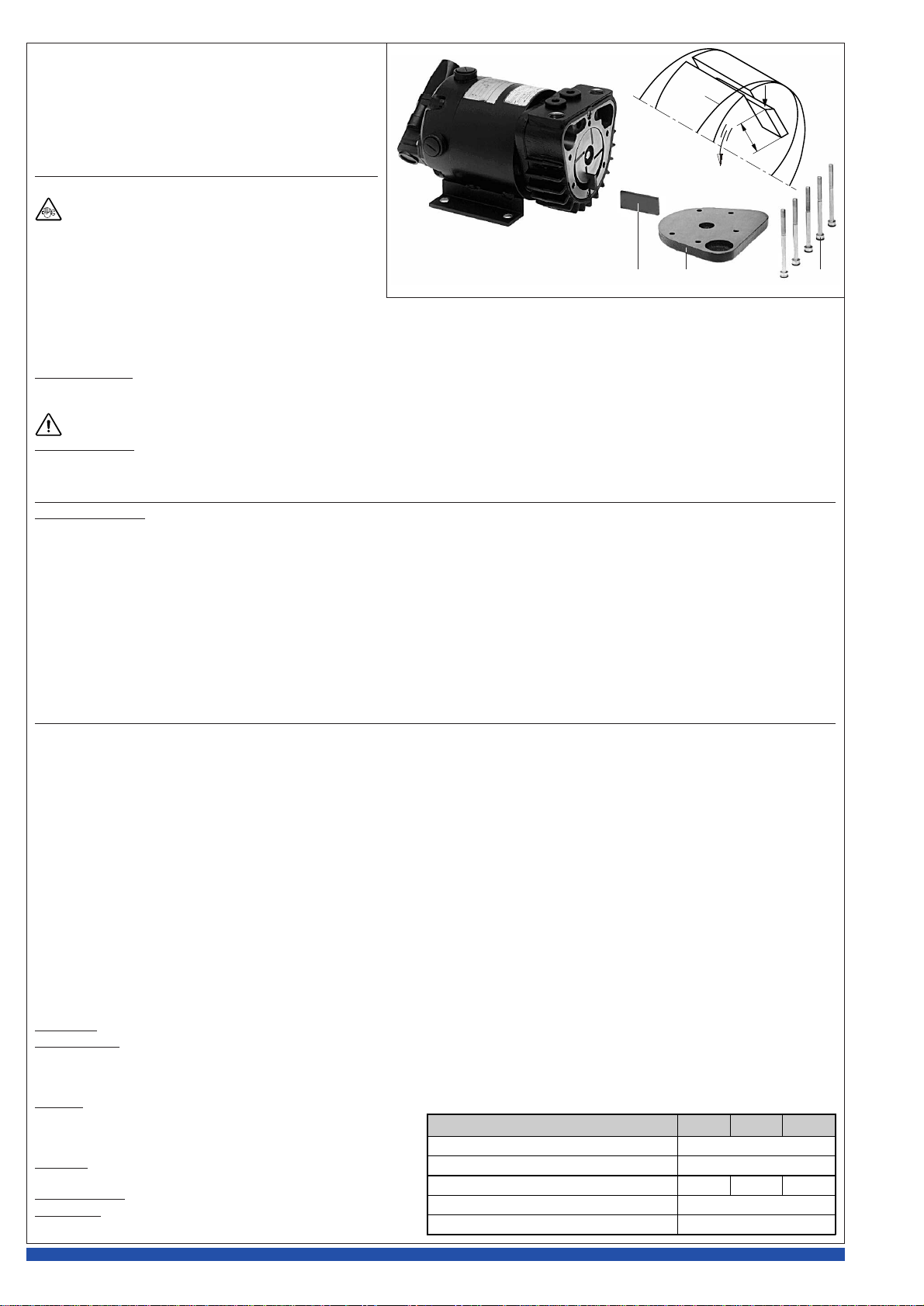
2. Lamellen (Bild )
Lamellenkontrolle: Die Type DTE hat 4 Kohlelamellen, die sich während des Betriebs allmählich abnützen.
Erste Kontrolle nach 6.000 Betriebsstunden, danach alle 1.000 Betriebsstunden. Gehäusedeckel (d) vom Gehäuse abschrauben. Lamellen (e)
zur Überprüfung herausnehmen. Alle Lamellen müssen eine Mindesthöhe (X) von größer als 12 mm haben.
Die Lamellen dürfen nur satzweise gewechselt werden.
Lamellenwechsel: Stellt man bei der Lamellenkontrolle fest, daß die Mindesthöhe bereits erreicht oder unterschritten ist, so ist der Lamellensatz
zuwechseln. Gehäuse und Rotorschlitze ausblasen. Lamellen in die Rotorschlitze einlegen. Beim Einlegen ist darauf zu achten, daß die Lamellen
mit der schrägen Seite (Y) nach außen zeigen und diese Schräge in Drehrichtung (O1) mit dem Verlauf der Gehäusebohrung (Z) übereinstimmt.
Gehäusedeckel (d) leicht anschrauben. Verdichter kurz einschalten und den freien Lauf der Lamellen überprüfen. Gehäusedeckelschrauben (s)
fest anschrauben.
Störungen und Abhilfe
1. Blasleistung ist ungenügend:
1.1 Vorfilter ist verschmutzt.
1.2 Druckleitung ist zu lang oder zu eng.
1.3 Undichtigkeit am Verdichter oder im System.
1.4 Lamellen sind beschädigt.
2. Enddruck (max. Überdruck) wird nicht erreicht:
2.1 Undichtigkeit am Verdichter oder im System.
2.2 Lamellen sind beschädigt.
3. Verdichter wird zu heiß:
3.1 Umgebungs- oder Ansaugtemperatur ist zu hoch.
4. Verdichter erzeugt abnormales Geräusch:
4.1 Das Verdichterhäuse ist verschlissen (Rattermarken). Abhilfe: Reparatur durch Hersteller oder Vertragswerkstatt.
4.2 Lamellen sind beschädigt.
Anhang:
Reparaturarbeiten: Bei Reparaturarbeiten vor Ort muß der Motor von einer Elektrofachkraft vom Netz getrennt werden, so daß kein unbeabsich-
tigter Start erfolgen kann. Für Reparaturen empfehlen wir den Hersteller, dessen Niederlassungen oder Vertragsfirmen in Anspruch zu nehmen,
insbesondere,wennes sichevtl. umGarantiereparaturenhandelt.DieAnschrift derfür SiezuständigenService-Stelle kannbeim Herstellererfragt
werden (siehe Hersteller-Adresse). Nach einer Reparatur bzw. vor der Wiederinbetriebnahme sind die unter “Installation” und “Inbetriebnahme”
aufgeführten Maßnahmen wie bei der Erstinbetriebnahme durchzuführen.
Lagerhaltung: Der DTE-Verdichter ist in trockener Umgebung mit normaler Luftfeuchtigkeit zu lagern. Bei einer relativen Feuchte von über 80%
empfehlen wir die Lagerung in geschlossener Umhüllung mit beige-
legtem Trockenmittel.
Entsorgung: Die Verschleißteile (als solche in der Ersatzteilliste
gekennzeichnet) sind Sonderabfall und nach den landesüblichen
Abfallgesetzen zu entsorgen.
Ersatzteilliste: E 387/50 ➝DTE 8 (50), (51), (52)
Datenblatt: 961271 ➝DTE 8 (50), (51)
961272 ➝DTE 8 (52)

DTE
DTE 8
(50), (51), (52)
B
Q
N
d
A
P O J
Operating Instructions
Compressors
Pump Ranges
These operating instructions concerns the following dry
running rotary vane compressor: DTE 8 (50), (51), (52)
Model DTE 8 has a capacity of 8 m3/hr. The overpressure
is 0.4 bar on S1 and 0.8 bar on S3 60%.
Description
Boththe motorandcompressorhave acommonshaft.The
versions (50), (51), (52) of the DTE differ in different plug
connections (J).
The compressor is driven by a DC motor.
Suitability
The units DTE are suitable for the use in the
industrial field i.e. the protection equipments
corresponds to EN DIN 294 table 4, for people aged 14
and above.
The DTE compressors produce compressed air up to the
maximum limits, which are shown on the data plate (N).
They may be operated continuously.
The ambient and suction temperatures must be
between -25 and +50°C. For temperatures outside this range please contact your supplier.
These dry running compressors are suitable for use with air of a relative humidity of 30 to 100%.
Dangerous mixtures (i.e. inflammable or explosive gases or vapours), water vapour, aggressive gases or
traces of oil and grease must not be handled.
The standard versions may not be used in hazardous areas.
All applications where an unplanned shut down of the compressor could possibly cause harm to persons
or installations, then the corresponding safety backup system must be installed.
Handling and Setting up
Compressors that have reached operating temperature may have on the DTE 8 a surface temperature at
position (Q) of more than 70°C. WARNING! Do Not Touch.
There must be a minimum space of 20 cm in front of the housing cover (d) for servicing.
The DTE compressors can only be operated reliably if they are installed horizontally. Other built-in positions
on request.
For installations that are higher than 1000 m above sea level there will be a loss in capacity. For further
advice please contact your supplier.
Installed on a solid base these compressors may be installed without fixing down. If the compressors are installed on
a base plate we would recommend fitting anti-vibration mounts. This range of compressors are almost vibration free in
operation.
Installation
For operating and installation follow any relevant national standards that are in operation.
1. Pressure connection at (B).
Long and/or small bore pipework should be avoided as this tends to reduce the capacity of the
compressor.
2. The electrical data can be found on the motor data plate (P). The motors correspond to DIN/VDE 0530 and have IP 65
protection and insulation class F. Check the electrical data of the motor for compatibility with your available supply
(voltage, polarity, permissible current etc.).
3. Connect the motor via plug-connection (J) anschließen (plug reference see data sheet 961271 or 961272).
The electrical installation may only be made by a qualified electrician under the observance of EN 60204.
The main switch must be provided by the operator.
BE 387/50
1.11.99
Werner Rietschle
GmbH + Co. KG
Postfach 1260
79642 SCHOPFHEIM
GERMANY
07622 / 392-0
Fax 07622 / 392300
E-Mail: [email protected]
http://www.rietschle.com
Rietschle (UK) Ltd.
Bellingham Way
NEW HYTHE
KENT ME20 6XS
UNITED KINGDOM
01622/716816
Fax 01622 / 715115
E-Mail: [email protected]
http://www.rietschle.co.uk

/ PM6
e d s
ZY
X
O
1
DTE 8 (50) (51) (52)
dB(A) 65
kg 9
mm 240 278 278
mm 128
mm 119
1.2001
Noise level (max.)
Weight
Length
Width
Height
Initial Operation (picture )
1. Initially switch the compressor on and off for a few seconds
to check the direction of rotation. With right direction of
rotation, air leaves at the pressure connection (B)
Note: The pressure pipework should not be connected.
If the compressor runs backwards this could result in
damaged rotor blades.
2. Connect the pressure pipe at (B).
Maintenance and Servicing
When maintaining these units and having such situ-
ations where personnel could be hurt by moving
parts or by live electrical parts the compressor must be
isolated by totally disconnecting the electrical supply
after free-switching. It is imperative that the unit cannot be
re-started during the maintenance operation.
Do not maintain a compressor that is at its normal operat-
ing temperature as there is a danger from hot parts.
1. Lubrication
The DTE compressors have bearings that are greased for life. They need not be serviced.
2. Blades (picture )
Checking blades: The models DTE have 4 blades which have a low but permanent wear factor.
First check after 6,000 operating hours, thereafter every 1,000 operating hours. Screw off housing cover (d) from housing. Remove blades (e)
for inspection. All blades must have a minimum height (X) of larger than 12 mm.
Blades must be changed completely.
Changing blades: if the minimum height is reached, then the whole set of rotor blades should be changed.
Before fitting new blades clean the housing and rotor slots with compressed air. Place the blades with the radius outwards (Y) so that the bevel
is in the direction of rotation (O1) and corresponds with the radius of the housing (Z). Replace housing cover (d) and slightly tighten the screws (s).
Start pump and check for free and smooth running blades. Then firmly tighten end cover screws (s).
Trouble Shooting:
1. Insufficient pressure capacity:
1.1 Prefilter is obscured.
1.2 Pressure pipe work is too long or too small.
1.3 Leak on the compressor or on the system.
1.4 Blades are damaged.
2. Compressor does not reach overpressure:
2.1 Leak on the compressor or on the system.
2.2 Blades are damaged.
3. Compressor operates at an abnormally high temperature:
3.1 Ambient or suction temperature too high.
4. Unit emits abnormal noise:
4.1 The compressor cylinder is worn. Solution: send your complete unit off for repair to the supplier or approved service agent.
4.2 Blades are damaged.
Appendix:
Repair on Site: For all repairs on site an electrician must disconnect the motor so that an accidental start of the unit cannot happen.
Allengineersarerecommendedtoconsulttheoriginalmanufactureroroneofthesubsidiaries,agentsorserviceagents.Theaddressofthenearest
repair workshop can be obtained from the manufacturer on application.
After a repair or before re-installation follow the instructions as shown under the headings ”Installation and Initial Operation”.
Storage: DTE units must be stored in dry ambient conditions with
normal humidity. We recommend for a relative humidity of over 80%
that the compressor units should be stored in a closed container with
the appropriate drying agents.
Disposal: The wearing parts (as listed in the spare parts lists) should
be disposed of with due regard to health and safety regulations.
Spare parts list: E 387/50 ➝DTE 8 (50), (51), (52)
Data sheet: 961271 ➝DTE 8 (50), (51)
961272 ➝DTE 8 (52)
This manual suits for next models
3
Table of contents
Languages:
Other Rietschle Air Compressor manuals
Popular Air Compressor manuals by other brands

MRC
MRC COMP-61 Operation manual

Craftsman
Craftsman 15201 owner's manual

Campbell Hausfeld
Campbell Hausfeld IN629500AV Operating instructions and parts manual

Leader
Leader 15BARS user manual

Porter-Cable
Porter-Cable CPFAC2600P instruction manual

RIX Industries
RIX Industries MAN-2PS2B-.85 operating instructions