2
Laser Triangulation Sensors. RF602 Series
RF602 [Revision 1.2.0] 28.01.2019
Contents
.............................................................................................................................................41. Safety precautions
.............................................................................................................................................42. CE сompliance
.............................................................................................................................................43. Laser safety
.............................................................................................................................................44. General information
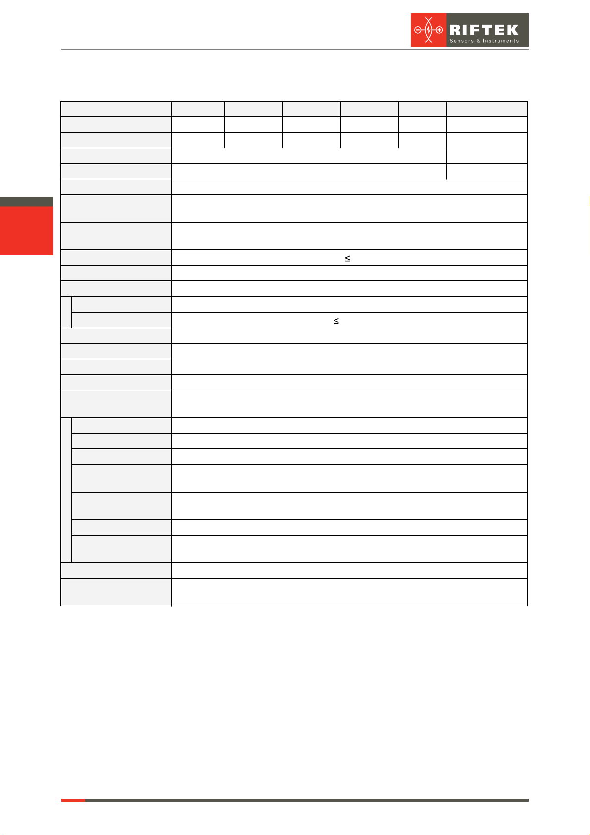
.............................................................................................................................................55. Basic technical data
.............................................................................................................................................66. Example of item designation when ordering
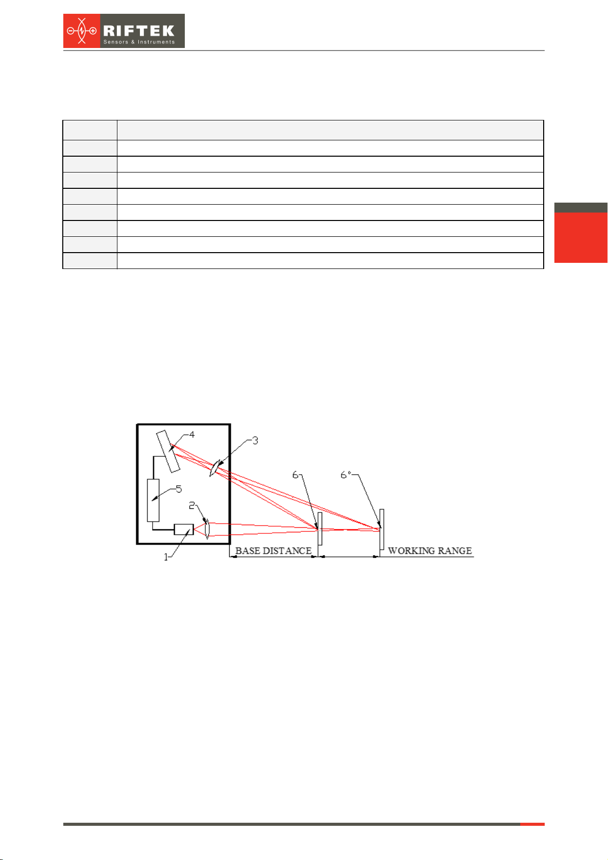
.............................................................................................................................................67. Structure and operational principle
.............................................................................................................................................68. Dimensions and mounting
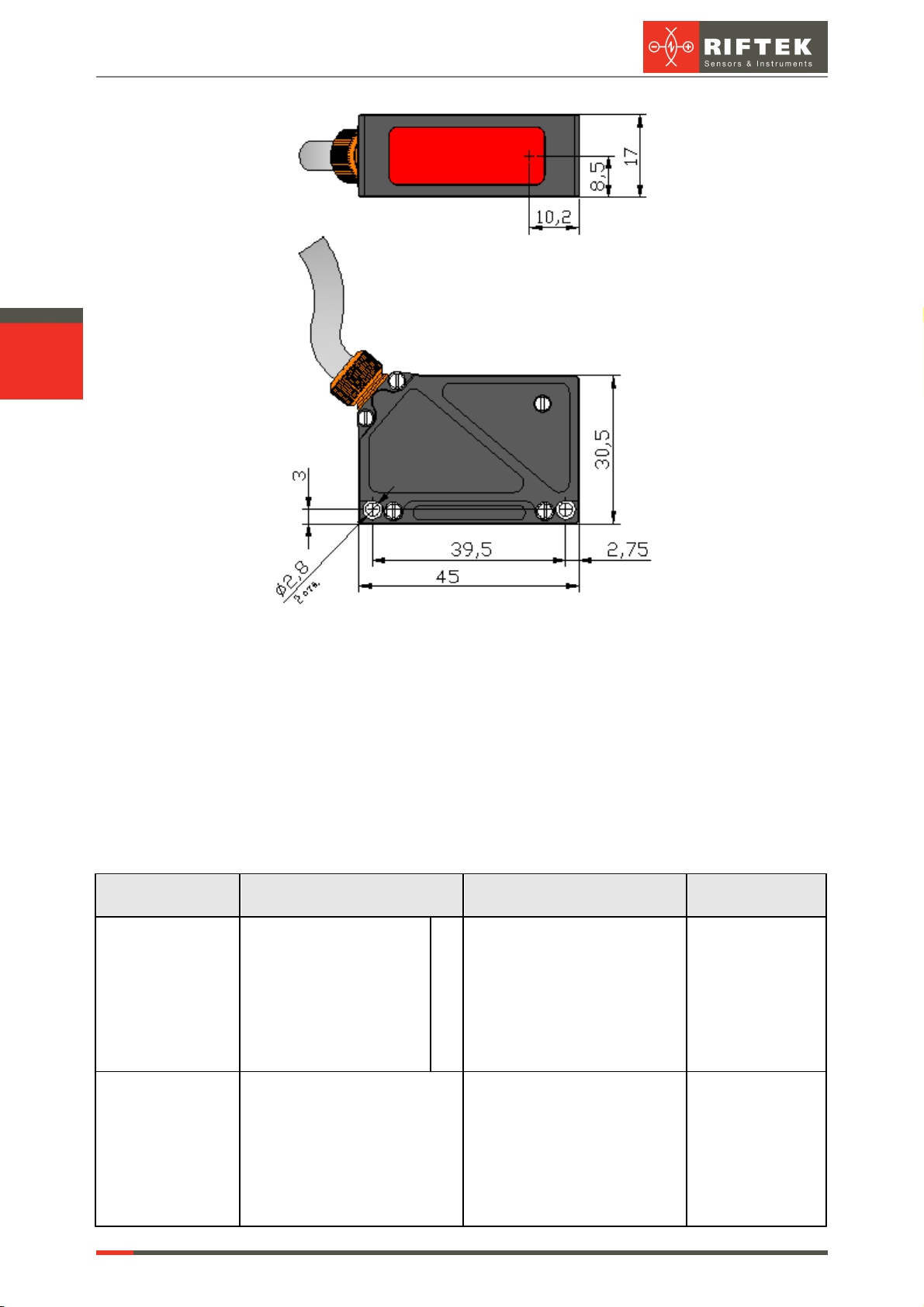
........................................................................................................................................... 68.1. Overall and mounting dimensions
........................................................................................................................................... 78.2. Overall demands for mounting
.............................................................................................................................................79. Connection
.............................................................................................................................................810. Configuration parameters
........................................................................................................................................... 810.1. Time limit for integration
........................................................................................................................................... 810.2. Sampling mode
........................................................................................................................................... 810.3. Sampling period
........................................................................................................................................... 910.4. Zero point
........................................................................................................................................... 910.5. Line AL operation mode
........................................................................................................................................... 1010.6. Time lock of the result
........................................................................................................................................... 1010.7. Method of results averaging
........................................................................................................................................... 1010.8. Number of averaged values/time of averaging
........................................................................................................................................... 1110.9. Factory parameters table
.............................................................................................................................................1111. Description of RS232 and RS485 interfaces
........................................................................................................................................... 1111.1. RS232 port
........................................................................................................................................... 1111.2. RS485 port
........................................................................................................................................... 1111.3. Serial data transmission format
........................................................................................................................................... 1111.4. Modes of data transfer
........................................................................................................................................... 1111.5. Communication sessions types
........................................................................................................................................... 1211.6. Configuration parameters
................................................................................................................. 1211.6.1. Rate of data transfer through serial port
................................................................................................................. 1211.6.2. Net address
................................................................................................................. 1211.6.3. Factory parameters table
........................................................................................................................................... 1211.7. RIFTEK protocol (binary format)
................................................................................................................. 1211.7.1. Request ................................................................................................................. 1311.7.2. Answer ................................................................................................................. 1311.7.3. Data stream
................................................................................................................. 1311.7.4. Output rate
................................................................................................................. 1311.7.5. Request codes table
................................................................................................................. 1411.7.6. List of parameters
................................................................................................................. 1511.7.7. Notes ................................................................................................................. 1511.7.8. Examples of communication sessions
........................................................................................................................................... 1811.8. Modbus RTU protocol (binary format)
................................................................................................................. 1811.8.1. Input Registers (Read only)
................................................................................................................. 1811.8.2. Holding Registers (Read / Write)
........................................................................................................................................... 1911.9. ASCII format
.............................................................................................................................................2012. Analog outputs
........................................................................................................................................... 2012.1. Current output 4…20 mA
........................................................................................................................................... 2112.2. Voltage output 0…10 V
........................................................................................................................................... 2112.3. Configuration parameters
................................................................................................................. 2112.3.1. Range of the analog output
................................................................................................................. 2112.3.2. Analog output operation mode
........................................................................................................................................... 2112.4. Factory parameters table
.............................................................................................................................................2113. Parameterization program