8
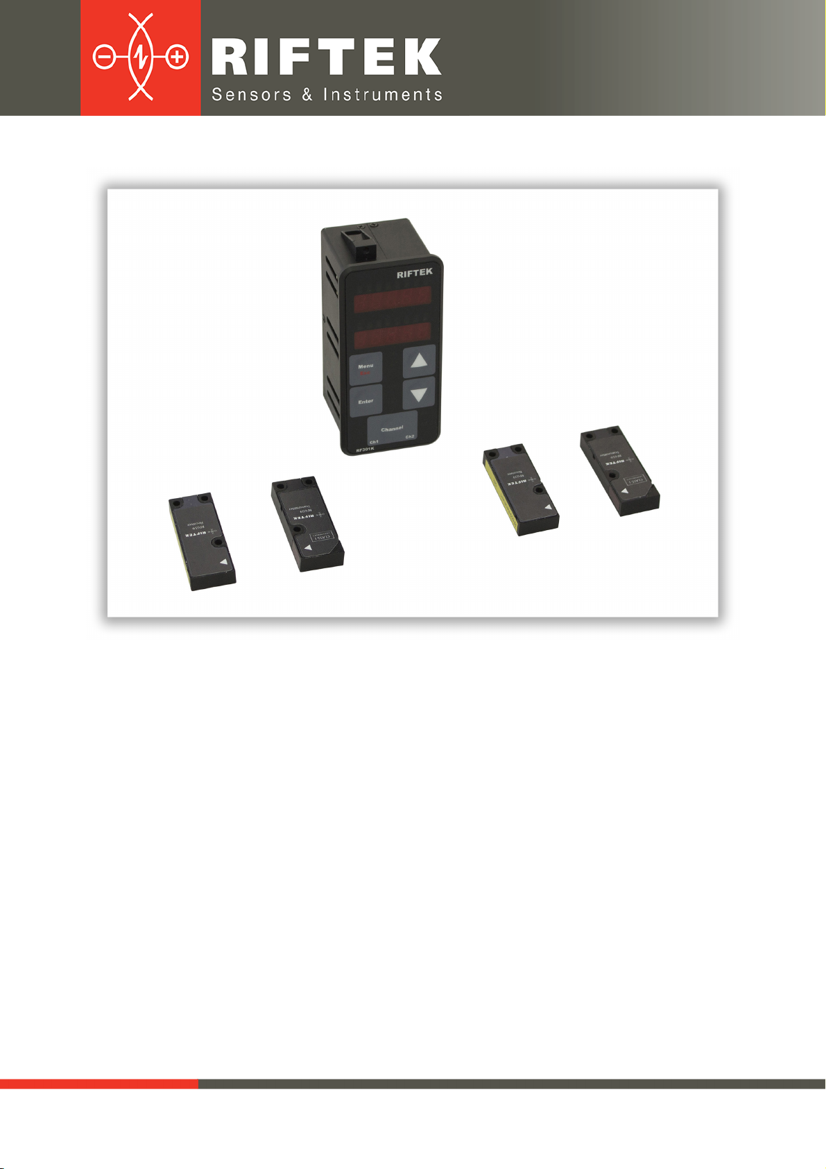
Edge Sensors. RF659 Series
RF659 [Revision 2.0.0] 26.06.2018
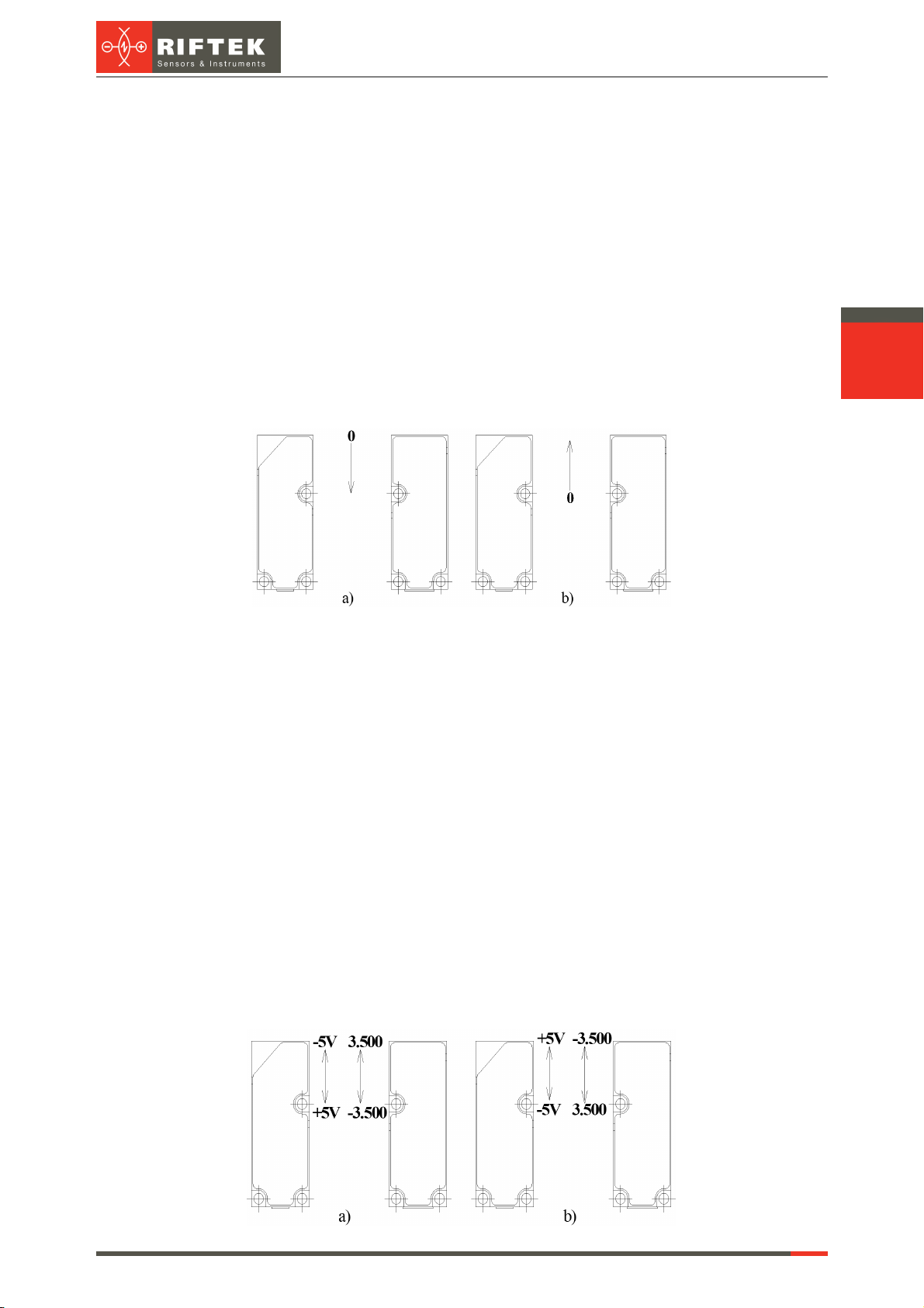
9.3. 'Technological elements ignoring' mode
Under technological elements to be understood objects in the test material,
projecting with respect to its edge (pins, fasteners and so on), or slots, technological gaps
and the like in the edge. Technological elements affect the correct measurement of the
material edge position. The device has the ability to ignore the technological objects in the
measurement process to ensure stable control of the main edge position.
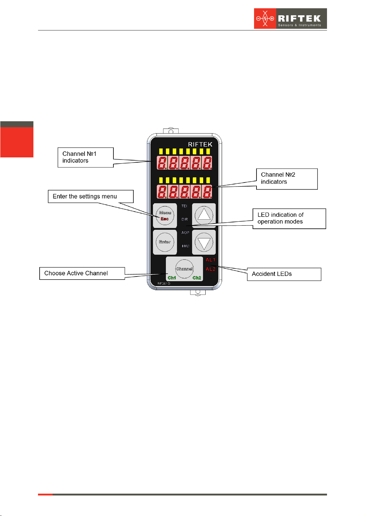
Press the Channel button and select the channel. The current channel number is
highlighted by LED.
Enter the menu, select "tEI.x" using the arrows, and press Enter to enter the
submenu.
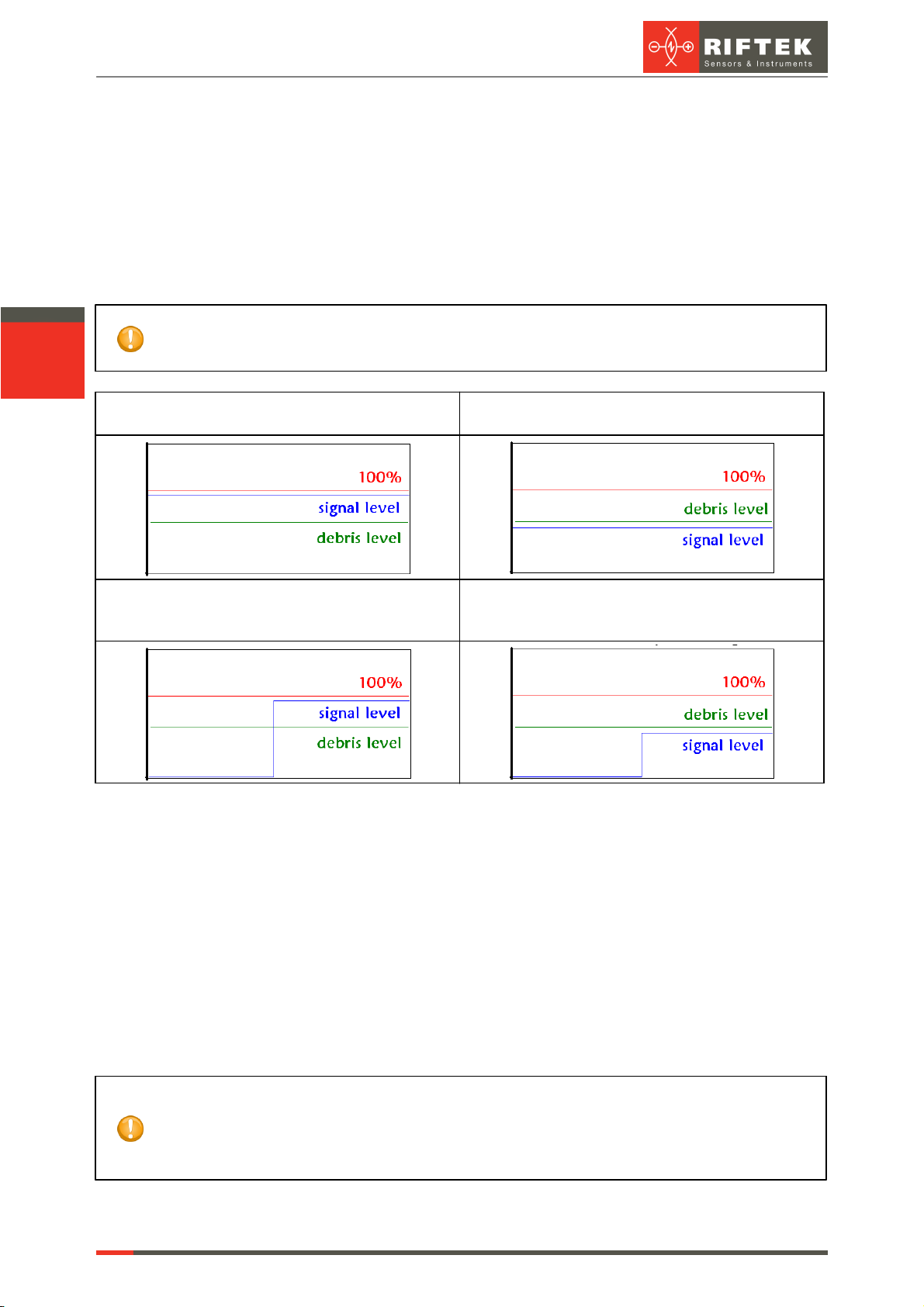
9.3.1. Detection threshold
Detection threshold sets a value, going beyond that is considered as the time of
technological element detection. The parameter sets positive and negative thresholds
simultaneously, i.e. if parameter is equal to 1.000 mm, all the values above 1 mm and below
-1 mm trigger the 'Technological elements ignoring' mode.
Indication of parameter number – the leftmost LED lights up on the LED line.
Display 1 shows the "thrES" message (Detection threshold), Display 2 shows the
parameter value.
To edit the parameter, use the Up and Down buttons. To increase the parameter,
press Up. To decrease the parameter, press Down. In order to go to the next parameter,
press Enter.
9.3.2. Analog output retention time
Analog output status remains unchanged since the detection the of technological
object and within the time specified by this parameter. The value of analog output
corresponds to the last value before the operation mode begins.
Indication of parameter number – two leftmost LED light up on the LED line. Display
1 shows the "AOrt" message (Analog output retention time), Display 2 shows the
parameter value.
To edit the parameter, use the Up and Down buttons. To increase the parameter,
press Up. To decrease the parameter, press Down. In order to go to the next parameter,
press Enter.
9.3.3. Lock range of the mode
At the end of analog output holding time, during the lock mode interval, the event of
the going beyond threshold is not processed. Analog output level corresponds to the current
measured value. This parameter is intended to allow the edge position adjustment of the
material in the event of going beyond the threshold during time when the analog output was
held. Indication of parameter number – three leftmost LED light up on the LED line.
Display 1 shows the "LrAng" message (Lock range of the mode), Display 2 shows the
parameter value.
To edit the parameter, use the Up and Down buttons. To increase the parameter,
press Up. To decrease the parameter, press Down. In order to go to the next parameter,
press Enter.
9.3.4. Enabling/disabling the mode
Indication of parameter number – four leftmost LED light up on the LED line. Display
1 shows the "StAtE" message, Display 2 shows the parameter value. To edit the
parameter, use the Up and Down buttons. To enable the mode, press Up. To disable the
mode, press Down. In order to go to the main menu, press Enter.