Rinnai MP2200 User manual

Commercial Manifold Pack
Operation & Installation Manual

Rinnai 2 Commercial Manifold Pack OIM
Congratulations on the purchase of your Rinnai Manifold Pack System. We trust you will have many years of
comfort and enjoyment from your appliance.
IMPORTANT
BEFORE USING THIS APPLIANCE
Before proceeding with the operation or installation, read this manual thoroughly and gain a full
understanding of the appliance, to ensure safe and correct use.
IMPORTANT NOTICE FOR INSTALLERS
Please leave these instructions with the end user after commissioning of the system and alert the
end user of the content sections “Warnings” and “Periodic Inspection” and ‘Maintenance”.
Not suitable as a pool or spa heater.
This manual must be read and understood before
installation, commissioning and operation of water heaters
and flue systems are attempted. The information
contained in other Operating / Installation instructions
supplied with water heaters applies in full, unless
otherwise dictated in this manual.
This appliance must be installed in accordance with:
• Manufacturer’s Installation Instructions
• Current AS/NZS 3000, AS/NZS 3500 & AS/NZS 5601
• Plumbing Code of Australia (PCA)
• Local Regulations and Municipal Building Codes
including local OH&S requirements
This appliance must be installed, maintained and removed
by an Authorised Person.
For continued safety of this appliance it must be installed
and maintained in accordance with the manufacturer’s
instructions.
All Rinnai gas products
sold in Australia are
A.G.A. certified.

Rinnai 3 Commercial Manifold Pack OIM
NOTE
INSTALLATION, SERVICE AND REMOVAL MUST BE BY AN AUTHORISED PERSON ONLY.
AS/NZS 5601 was current at the time of printing but may have been superseded. It is the Installer's
responsibility to ensure current requirements are met.
Remove transit protection lm. Check for damage, if any is found DO NOT install and contact
supplier.
TABLE OF CONTENTS
WARNINGS & IMPORTANT INFORMATION 4
Regulatory Information ....................................................................................................................................... 4
Warning About Hot Water ................................................................................................................................... 4
Model Range Overview ...................................................................................................................................... 5
Location .............................................................................................................................................................. 5
INTERNAL FLUEING 7
Co-Axial Flueing for Internal Models .................................................................................................................. 7
Common Flue System for Internal models ......................................................................................................... 8
INSTALLATION 10
Setting Sequence ............................................................................................................................................. 11
Manifold Pack with MECs or PAMs Staging (no reticulation system) ............................................................... 11
Manifold Pack without MECs or PAMs Staging (reticulation system) ............................................................... 11
Activated Manifold Pack without MECs or PAMs staging (reticulation system) ............................................... 12
Typical Rinnai Manifold Pack Installation ......................................................................................................... 13
Appliance Dimensions .................................................................................................................................. 13
Rinnai Manifold Pack Installation Hand Over Manual ...................................................................................... 15
Rinnai Manifold Electronic Control System - MECS ......................................................................................... 15
CONDENSATE DRAIN 16
REU-KM & REU-N Models Only ..................................................................................................................... 16
Installation Method ........................................................................................................................................... 16
FAULT FINDING 18
Manifold Pack Preventative Maintenance ........................................................................................................ 18
Ring Main Pump ............................................................................................................................................... 19
Service ............................................................................................................................................................. 19
Contacts 20

Rinnai 4 Commercial Manifold Pack OIM
REGULATORY INFORMATION
Your Rinnai Continuous Flow water heater has been certied by the Australian Gas Association.
The A.G.A. Certication Number is shown on the data plate.
This Appliance must be installed correctly by an authorised person. The installation of gas, water, and electricity
must conform to local regulations. The installation must also comply with the instructions supplied by Rinnai.
All dimensions referred to in these instructions are in millimetres, unless otherwise specied. Please keep this
instruction booklet in a safe place for future reference.
This appliance is not intended for use by persons (including children) with reduced physical, sensory or mental
capabilities, or lack of experience and knowledge, unless they have been given supervision or instruction
concerning use of the appliance by a person responsible for their safety. Any power leads from the water heater
system components MUST BE plugged into an external weatherproof electrical outlet. If the power supply cord of
the system is damaged, it MUST BE replaced by an authorised person in order to avoid a hazard, using genuine
replacement parts available from Rinnai. Take care of not to touch the power plugs with wet hands.
Notice to Victorian Consumers
This appliance must be installed by a person licensed with the Victorian Building Authority a licensed person will
have insurance protecting their workmanship. So make sure you use a licensed person to install this appliance
and ask for your Compliance Certicate. For further information contact the Victorian Building Authority on 1300
815 127.
WARNING ABOUT HOT WATER
WARNING
This appliance may deliver water at high temperature. Refer to the Plumbing Code of Australia
(PCA), local requirements and installation instructions to determine if additional delivery
temperature control is required.
HEATED WATER CAN BE DANGEROUS, ESPECIALLY
FOR YOUNG CHILDREN AND THE INFIRM.
WATER TEMPERATURES ABOVE 50°C CAN CAUSE
SEVERE BURNS INSTANTLY AND MAY EVEN RESULT IN
DEATH.
THOSE MOST AT RISK ARE CHILDREN, DISABLED,
ELDERLY AND THE INFIRM.
HOT WATER AT 65°C (A VERY COMMON HOT WATER
TEMPERATURE IN AUSTRALIA) CAN SEVERELY BURN
A CHILD IN LESS THAN HALF A SECOND.
AT 50°C IT TAKES FIVE MINUTES.
ALWAYS......
Test the temperature of the water with your elbow before placing your child in the bath, also carefully feel
water before bathing or showering yourself.
Supervise children whenever they are in the bathroom.
Make sure that the hot water tap is turned o tightly.
CONSIDER.....
Installing child proof tap covers or child resistant taps (both approaches will prevent a small hand being
able to turn on the tap).
Setting your appliance at a maximum temperature of 50°C (Contact Rinnai Australia).
NEVER…..
Leave a toddler in the care of another child. They may not understand the need to have the water
temperature set at a safe level.
WARNINGS & IMPORTANT INFORMATION

Rinnai 5 Commercial Manifold Pack OIM
NOTE
INSTALLATION, SERVICE AND REMOVAL MUST BE BY AN AUTHORISED PERSON ONLY.
AS/NZS 5601 was current at the time of printing but may have been superseded. It is the Installer's
responsibility to ensure current requirements are met.
Remove transit protection lm. Check for damage, if any is found DO NOT install and contact supplier.
MODEL RANGE OVERVIEW
MP2200, MP2250, MP2210, ACMP2 200 either external or internal in NG or LPG
MP3200, MP3250, MP3210, ACMP3 200 either external or internal in NG or LPG
MP4200, MP4250, MP4210, ACMP4 200 either external or internal in NG or LPG
MP5200, MP5250, MP5210, ACMP5 200 either external or internal in NG or LPG
MP6200, MP6250, MP6210, ACMP6 200 either external or internal in NG or LPG
Rinnai Commercial Manifold Pack hot water systems must only be installed, commissioned, service and removed
by an authorised person in accordance with these instructions, AS/NZS 5601, AS/NZS 3000, AS/NZS 3500 and
local regulations and municipal building codes including local OH&S requirements.
Rinnai Manifold Pack hot water systems are not suitable or approved as a pool heater.
Read these instructions carefully before proceeding with the installation.
LOCATION
Ensure reasonable access for installation, servicing and removal. All valves, controls and pumps etc must be
easily accessible.
When using free standing frames the system must be mounted on a solid level base, capable of supporting the
weight of the appliance when full of water. Ensure components are not allowed to stand in water.
Manifold Pack can be plumbed “left handed”, “right handed” or “equal ow” as staging determines operating
sequence of heaters, not the plumbing. Stage-less or larger systems may need to be “equal ow”, contact Rinnai
Commercial for assistance.
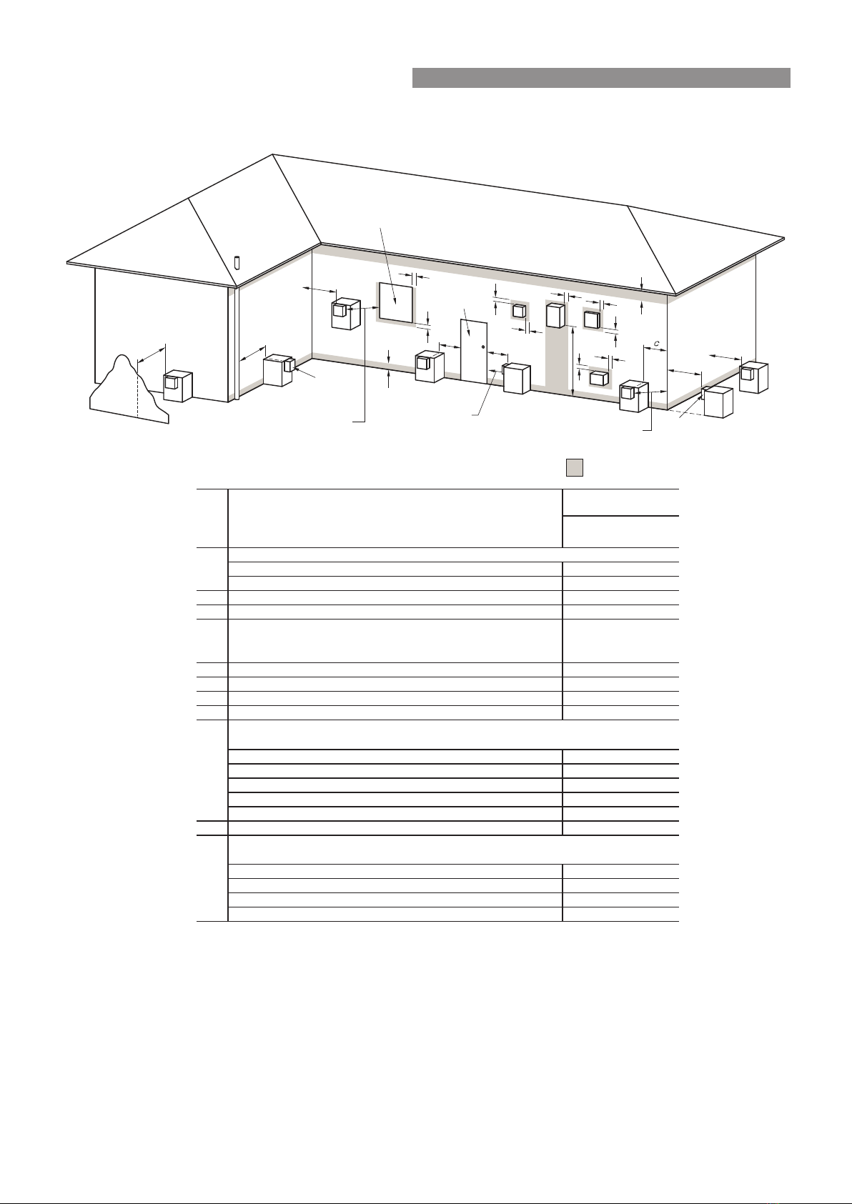
Gas booster ue terminals must be located in accordance with AS/NZS 5601 Fig 6.2 “Location of balanced ue
terminals”.
Rinnai HD units are fan assisted appliances and thus have lower clearances than a natural draft appliance of the
same MJ rating.
HD200e, HD250e, HD210e (External Models)
This appliance is designed for 'Outdoor' Installation only. As such,it must be located in an above ground open
air situation with natural ventilation, without stagnant areas, where gas leakage and products of combustion are
rapidly dispersed by wind and natural convection.
This appliance must be mounted on a vertical structure with the water and gas connections on the underside
pointing downwards. For appliances installed on elevated structures or under oors specic requirements apply.
Refer to AS/NZS 5601 Section 6 for details.
This appliance must not be used as a domestic spa or swimming pool heater.
Location of the appliance ue terminal must be in accordance with Section 6 and Figure 6.2 of AS/NZS 5601.
Figure 6.2 is reproduced in the 'Horizontal Flue Terminal Clearances' section of these instructions.
Note: that AS/NZS 5601 is current at the time of printing. It is the Installers' responsibility to ensure current
requirements are met.
HD200i, HD210i (Internal Models)
This appliance is designed for 'Indoor' installation only. It may be installed 'Outdoors' in an enclosure if the
requirements of AS/NZS 5601 Section 6 are satised. An enclosure is dened as a compartment, enclosed area
of partitioned o space primarily used for the installing of the appliance.
WARNINGS & IMPORTANT INFORMATION

Rinnai 6 Commercial Manifold Pack OIM
APPLIANCE FLUE TERMINAL
Horizontal Terminal Clearances (Extract from AS/NZS 5601)
Min. Clearances
(mm)
For appliances up to 50 MJ/h input 200
For appliances over 50 MJ/h input 300
300*ecafrusrehtoroynoclabaevoba,dnuorgehtmorFb
300*renroclanretxerollawnruteratnorFc
d
From a gas meter (M) (see Note 5)
(see Clause 5.11.5.9 for vent terminal location of regulator)
(see Table 6.7 for New Zealand requirements)
1000
eFrom an electricity meter or fuse box (P) † (see Note 5) 500
epipliosroepipniardamorFf
gHorizontally from any building structure* = or obstruction facing a terminal 500
hFrom any other flue terminal , cowl, or combustion air intake * 300
Appliances up to 150 MJ/h input * 300
Appliances over 150 MJ/h input up to 200 MJ/h input * 300
Appliances over 200 MJ/h input up to 250 MJ/h input * 500
Appliances over 250 MJ/h input * 1500
All fan-assisted flue appliances, in the direction of discharge 1500
1000rewolbapsagnidulcni,telnirialacinahcemamorFk
Space heaters up to 50 MJ/hr input
Other appliances up to 50 MJ/hr input 500
Appliances over 50 MJ/h input and up to 150 MJ/h input 1000
Appliances over 150 MJ/h input 1500
metI.feR
a
Below eaves, balconies and other projections:
FIGURE 6.2 (in-part) LOCATION OF FLUE TERMINALS OF BALANCED FLUE,
ROOM-SEALED, FAN-ASSISTED OR OUTDOOR APPLIANCES
n
j
Horizontally from an openable window, door, non-mechanical air inlet, or any other opening into a
building with the exception of sub-floor ventilation:
Vertically below an openable window, non-mechanical air inlet, or any other opening into a
building with the exception of sub-floor ventilation:
Where dimensions c, j or k cannot be achieved an equivalent horizontal distance measured
diagonally from the nearest discharge point of the terminal to the opening may be deemed by
the Technical Regulator to comply.
See Clause 6.9.4 for restrictions on a flue terminal under a covered area.
See Figure J3 for clearances required from a flue terminal to an LP Gas cylinder. A
flue terminal is considered to be a source of ignition.
For minimum clearances not addressed above acceptance should be obtained from the
Technical Regulator.
Minimum clearances d and e also apply to any combustion air intake openings of appliances.
1
2
3
4
5
* Unless appliance is certified for closer installation.
† Prohibited area below electricity meter or fuse box extends to ground level.
NOTES:
75
Sha ding i n dicates pr o hibite d
ar e a for flue ter m inals
LEGE ND:
I= Mecha nical a ir inl et
S= Str u c ture
M= Ga s m ete r
T= Fl ue te r minal
P= El e c tr i c it y meter or fu se box
Z= Fan-ass i ste d a p plia n ce only
Dir e ction of
discharge
See N o te 1
See N o te 1
Opening into
a building
T
T
T
T
T
T
T
C
M
d
d
e
e
h
j
j
j
n
b
f
a
h
P
Z
S
k
k
g
g
g
I
T
Door
Fan
assisted
150
WARNINGS & IMPORTANT INFORMATION

Rinnai 7 Commercial Manifold Pack OIM
CO-AXIAL FLUEING FOR INTERNAL MODELS
The Rinnai Continuous Flow Flueing system must be installed in accordance with the instructions supplied with
the ue terminal. Non Rinnai ueing systems MUST NOT be used. For all further information on Internal Flueing,
please refer to separate Flueing manual supplied with Flueing components.
Installations can consist of both horizontal and vertical runs to a
maximum of 9 metres with a maximum of three 90° bends.
The Rinnai Internal Flueing system is highly versatile and makes
installation of an internal water heater simple and convenient. The ueing
for internal water heaters is a Co-axial design. It is manufactured from an
aluminium alloy inner ue pipe to discharge product of combustion and a
thermoplastic outer pipe for air supply to the appliance. The water heater
is a room sealed appliance.
Note: Each Rinnai water heater is ued individually.
As it is fan assisted, the heater can be ued vertically, horizontally or any
combination of both, to a maximum of 9 metres and 3 x 90 degree bends.
Horizontal ueing can be used as a direct wall ue or extended from
another internal wall.
Vertical ueing is used when the water heater needs to be ued vertically
through the roof.
A condensate trap is required when vertical ue exceeds 1.5 metres.
Rinnai HD internal water heaters are classied as 'room sealed'
appliances. Flue systems must be installed in accordance with Rinnai
Installation Instructions (supplied with the ue terminals), local gas
tting regulations, municipal building codes, AS/NZS 5601 and all other
relevant statutory regulations.
The ue terminal clearances AS/NZS 5601 DO NOT apply to the HD200e
and HD250e heaters installed side by side.
These appliance are AGA certied to be located side by side, for both
internal and external models.
Manifold Pack 5
Manifold Pack 3
NOTE
Only Rinnai Flueing Systems can be used with Internal Water Heaters. Non-Rinnai Flueing systems
are not certied and will not be covered under warranty.
Have you used only RINNAI FFU flueing components?
1
OFF
SW1
For Internal (FFU) models only
If flue length exceeds 2m, dip-switch 1 of SW1 is to be switched to the ‘OFF’ position as shown.
For all further information on Internal Flueing, please refer to separate Flueing manual supplied with Flueing
components.
INTERNAL FLUEING

Rinnai 8 Commercial Manifold Pack OIM
COMMON FLUE SYSTEM FOR INTERNAL MODELS
The Rinnai Commercial Common Flue System is suitable for the Rinnai Internal Commercial Gas Continuous
Flow Water Heaters in accordance with the ue design options outlined in the AS/NZS 5601.1 Appendix titled
"Flue Design". Figure 1 and Figure 2 below, illustrate typical application principles.
Figure 1. Typical Natural Draft Flue Installation - VRM/VCM-Series ONLY
Figure 2. Typical Power Flue Installation - Both N-Series & VRM/VCM-Series
RINNAI FLUE HEADER(S)
NATURAL DRAFT FLUE PIPE
SUPPLIED BY OTHERS/
ALREADY INSTALLED
CERTIFIED FLUE COWL
CONDENSATE DRAIN
WHERE NECESSARY
RINNAI ADJUSTABLE SLEEVE/OR EQUIVALENT
BEND DDADJSLV
OR EQUIVALENT
MULTIPLE RINNAI
WATER HEATERS
ROOF
RINNAI COMMON FLUE
INSERT TERMINAL
ENDCAP
FAN FAILURE SENSING
DEVICE INTERLOCKED WITH
GAS SUPPLY TO APPLIANCES
FAN
DAMPER ADJUSTING
DILUTION AIR
MULTIPLE RINNAI NON
CONDENSING WATER HEATERS
EXTERNAL WALL
EXTERNAL WALL
FLUE PIPE SUPPLIED BY
OTHERS / ALREADY INSTALLED
RINNAI FLUE HEADER(S)
EXHAUST OF DILUTED
COMBUSTION AIR
INTAKE OF FRESH AIR
PLANT ROOM VENTILATION
AND COMBUSTION AIR
RINNAI COMMON
FLUE INSERT TERMINAL
RINNAI ADJUSTABLE
SLEEVE / BEND
OR EQUIVALENT
(Note 1)
INTERNAL FLUEING

Rinnai 9 Commercial Manifold Pack OIM
Multiple Appliance Installations
Dimension ‘h’ in reference to Horizontal Terminal
Clearances (Extract from AS/NZS 5601) on page 6
does not apply when multiple Rinnai external water
heaters of the same model are installed on the same
vertical face with ue terminals at the same height.
Under these conditions appliances can abut each other
as shown. The total gas consumption of all appliances
applies when determining other clearances.
For all other appliance dimensions, refer to "Appliance
Dimensions" on page 13.
IMPORTANT
Rinnai internal models described in this manual must use the Co-Axial Rinnai FFU ue components.
The use of non Rinnai FFU ue components may result in a dangerous situation and violates
regulations.
The FFU ue system must be installed in accordance with the ‘FFU Flue Installation Manual’
which is provided with the FFU ue terminal components FFWALLTERM or FFROOFCOWL.
Installations can consist of both horizontal and vertical runs to a maximum length of 9 metres
and with a maximum of three 90° bends.
Basic methods of installation
There are four basic ue installation methods available,
these are:
1
Direct Horizontal
2
Extended Horizontal
3
Vertical
4
Combination Vertical / Horizontal
Short and Long Flue Length Settings
Short Flue
When the ue length does not exceed 1.5m then: Dip
switch 1 of SW1 is to be switched to the 'ON' position.
Long Flue
When the ue length exceeds 1.5m the: Dip switch 1 of
SW1 is to be switched to the 'OFF' position (This increases
the combustion speed to overcome the additional friction
loses).
Multiple Terminal Installations
The terminal clearances stated in AS/NZS 5601 do not
apply to the Rinnai internal continuous ow water heaters
when they are installed side by side.
AGA certication allows for a horizontal separation of 160
mm for roof terminals and 270 mm for wall terminals.
12
3
4
OFF ON
SW1
12345678
FFU (Internal) Models Only
Short Flue: Total flue
length less than 1.5 metres
OFF ON
SW1
12345678
FFU (Internal) Models Only
Extended Flue: Total flue
length 1.5 metres or greater
Flue Length Dip Switch Settings
Dipswitches
SW1
Dipswitches
SW2
350
350
225
160
270
FFROOFCOWL
FFWPLATE
FFROOFCOWL
INTERNAL FLUEING

Rinnai 10 Commercial Manifold Pack OIM
Unpacking
Manifold Packs are supplied in cardboard packaging in separate modules of MP2 and MP3. Systems are packed
upside down. When turning over to correctly orient heaters beware that system is top heavy.
Assembly:
A Rinnai Manifold Pack is supplied in modules of either 2 or 3 HD continuous ow units plumbed in parallel
and mounted on a dedicated and lightweight frame. Standard systems can be installed together in any order by
coupling the barrel unions supplied with the 32mm copper header pipes. Specically designed systems (generally
for larger projects or restrictive plant areas) will be marked up accordingly from our factory to aid the on site
assembly process.
You may have an activation system included on your Manifold Pack, if this is the case then there will be a pump
(or dual pumps) assembly provided and additional lengths of insulated copper pipe to connect together. This is
located below the cold header pipe. Below is a typical image of how an activated circulating Manifold Pack should
be assembled and installed (only required on Manifold Packs including a reticulation system) with the cold inlet on
the right. This can also be provided in the opposite orientation with the cold inlet on the right and therefore the hot
outlet must be on the left.
INSTALLATION

Rinnai 11 Commercial Manifold Pack OIM
Wall mounting or oor mounting is possible. If you are wall mounting the Manifold Pack then drill holes in the wall in
the desired location and mount the frame to the wall using suitable xings. If you wish to oor mount the Manifold
Pack then you will require an appropriate DDBASE if the unit has been pre-supplied on a factory made skid base
you are not required to do anything. A DDBASE requires some minor assembly using the brackets and xings
provided.
Manifold Packs used in buildings without a reticulation system will have a staging system either a Manifold Electronic
Control System (MECs) or Pressure Activated Manifold System (PAMs). MECs is a sophisticated electronic control
system that is supplied pre-wired except for joining the modules together. Refer to the separate MECs installation
booklet supplied for full details on how to connect each heater control. PAMs is a mechanical staging system
using a pressure sensitive valve installed on the cold supply riser to each heater except the rst one. PAMs has
a maximum capacity of 6 heaters and needs to be setup on installation to operate correctly. Each valve needs to
have the pressure sensitive plunger set dependant on how many heaters are present.
SETTING SEQUENCE
• First HD = no PAM valve present
• Second HD = Plunger in furthest out position
• Third HD = Plunger in furthest out position
• Fourth HD = Plunger in middle position
• Fifth HD = Plunger in lowest position
• Sixth HD = Plunger in lowest position
Starting instructions
These dier depending on the Manifold Pack and installation conguration
MANIFOLD PACK WITH MECS OR PAMS STAGING (NO RETICULATION SYSTEM)
• Turn on power to each heater via the GPO’s
• Open one or more outlets to generate water ow through the heaters. The outlet temperature should appear
in the maintenance monitor window on each heater. This is factory preset at 75° but can be adjusted if
required, refer to relevant temperature settings for heaters. This indicates the units are operational.
• Not all Rinnai heaters will re up as its ow rate dependent. To verify all heaters are operational either open
more outlets or, if this is not practical, close the cold water valve underneath the currently operating heaters
to restrict the ow. Other heaters should then re up.
• Clean all lters on completion
MANIFOLD PACK WITHOUT MECS OR PAMS STAGING (RETICULATION SYSTEM)
• Turn on power to each heater via the GPO’s
• Turn on the Ring Main pump to generate water ow through the heaters. The outlet temperature should
appear in the maintenance monitor window on each heater. This is factory preset at 75° but can be adjusted
if required, refer to relevant temperature settings for heaters. This indicates the units are operational.
• Not all heaters may re up as its ow rate dependent. To verify all heaters are operational either open some
outlets or, if this is not practical, close the cold water valve underneath the currently operating heaters to
restrict the ow. Other heaters should then re up.
• Clean all lters on completion
INSTALLATION

Rinnai 12 Commercial Manifold Pack OIM
ACTIVATED MANIFOLD PACK WITHOUT MECS OR PAMS STAGING (RETICULATION SYSTEM)
• Turn on power to each heater via the GPO’s
• Turn on power to the activation pump via the GPO to generate water ow through the heaters
• Turn on the Ring Main pump to generate water ow around the building. The outlet temperature should
appear in the maintenance monitor window on each heater. This is factory preset at 75° but can be adjusted
if required, refer to relevant temperature settings for heaters. This indicates the units are operational.
• Not all heaters may re up as its ow rate dependent. An activated Manifold Pack is designed to deliver an
accurate temperature to the building without relying on the ow of the ringmain pump. Therefore the ow
rate through the heaters is controlled by the valve on the outlet of the activation pump. This should be as
low as can be achieved without aecting the acceptable delivery temperature and there is no typical valve
setting as every hot water reticulation system is dierent. To activate more heaters wind open the valve until
satised that the delivery temperature is sucient to maintain the temperature in the loop. Refer drawing
below.
• Clean all lters on completion.
INSTALLATION

Rinnai 13 Commercial Manifold Pack OIM
TYPICAL RINNAI MANIFOLD PACK INSTALLATION
C
A A
B
H
ED F G
NOTE: ACTIVATION LOOP MAY BE FITTED
Appliance Dimensions
Model A B C D E F GH Dry
Weight
HD200 Manifold Packs
MP2 200
375
750
280 340 440 540 1500 850
60 Kg
MP3 200 1125 90 Kg
MP4 200 1500 120 Kg
MP5 200 1875 150 Kg
MP6 200 2250 180 Kg
HD210 Manifold Packs
MP2 210
500
1000
310 340 440 540 1500 850
75 Kg
MP3 210 1500 110 Kg
MP4 210 2000 150 Kg
MP5 210 2500 185 Kg
MP6 210 3000 225 Kg
INSTALLATION

Rinnai 14 Commercial Manifold Pack OIM
Cold Water Supply:
• Cold water pipe work to inlet of MP, including required valves as shown above to comply with AS/NZS 3500
and local regulations. Non return valve not required for deadleg installations.
• Maximum cold water inlet pressure to Manifold Pack is 1000kPa. Fit pressure limiting valve if required.
• When a Ring Main pump is included ensure cold water inlet pressure does not exceed maximum pump
rating. This is usually mains pressure plus pump head pressure (eg: 750 kPa mains +250 kPa pump head
pressure =1000kPa).
Hot Water Outlet
• Ensure adequate insulation / lagging is tted to hot water pipe to minimise heat loss.
Ring Main Pump
• A secondary or building return pump may be installed in conjunction with the Rinnai Manifold Pack hot water
system. Contact Rinnai Commercial to select this pump as duty is critical to temperature stability when there
is no building ow. Pump must have a check valve on the discharge.
• Return line from building loop is connected to the cold water supply pipe after the check valve. From that
point onwards the cold pipe should be insulated.
Gas Supply
• Check gas type of Rinnai HD water heater matches gas supply available (LPG or Natural) on job site.
• Gas inlet connection is the top pipe on a MP manifold.
• Manifold Packs have gas isolation valves per water heater.
• Ensure gas pipe sizing is adequate to deliver the required volume / pressure. Pipe size used on inlet tting
is no indication of pipe size required.
• Refer to appropriate pipe sizing chart in Appendix “F” AS/NZS 5601 for appropriate sized gas pipe that
should be used to ensure adequate gas supply.
• Gas meter / LPG cylinder and regulator should also be of suitable size to ensure sucient gas supply to the
gas installation.
• Purge gas pipe to ensure removal of debris etc prior to nal connection.
• Check for gas escapes using suitable methods as listed in Appendix “E” AS/NZS 5601.
Electrical Supply
• 100 amps per HD do not exceed 24 units to one GPO.
Filling Instructions
• Flush pipe work to remove any debris before nal connection.
• Turn on hot water tap to allow air to be expelled from system.
• Check all connections for water leakage. Tighten as required.
• Purge gas lines until gas is available at water heaters.
• Prime circulating pump(s) before start up by removing chrome screw and allowing water to drip out the end
of the pump shaft.
INSTALLATION

Rinnai 15 Commercial Manifold Pack OIM
RINNAI MANIFOLD PACK INSTALLATION HAND OVER MANUAL
Manifold Pack Principle Of Operation
Cold water enters system through cold inlet pipe is heated by water heater(s) and exits through hot pipe. Dead-leg
systems will deliver preset temperature as per dipswitch or controller settings.
Rinnai Heavy Duty Units require a minimum of 2.4 litres per minute per heater before they can operate. If this is
not achieved they will not re. When there is an expected scenario that results in a lower ow per heater a staging
system is required. Rinnai oer MECS (Manifold Electronic Control System) or PAM (Pressure Activated Manifold)
valves. Staging will control the ow through each water heater, increasing the chance of minimum ow rate being
achieved. MECS measures the ow rate passing through the turbine of each heater. It will drive the geared motor
inside the HD unit shut in heaters that are not required to operate, therefore increasing the ow rate through the
remaining heaters. Extra heaters are red as the ow rate increases. MECS also rotates the sequence of operation
to share the load across all heaters to maximise life expectancy.
PAM valves block the cold water supply to heaters that are not required. Therefore they do not start. Extra ow
causes extra pressure dierential between the hot and cold pipes opening more PAM valves and ring more HD
heaters.
RINNAI MANIFOLD ELECTRONIC CONTROL SYSTEM - MECS
Rinnai Heavy Duty Gas Fired Continuous Flow Water Heaters can be manifolded together, (up to 25 individual
water heaters), by connecting them in parallel to enable a far greater hot water ow rate than is possible with a
single unit.
MECS is a totally integrated system unique to Rinnai that links each HD unit in the system and will turn on each
unit in the system as demand requires.
The key advantages to using MECS are as follows:
• Very high ow rates/volumes made possible by linking individual heaters in parallel.
• Load shared across linked heaters ensuring even wear rates.
• Inherent redundancy in the event of a failed water heater(s).
• Reduced gas consumption resulting in increased economy.
• Unsurpassed water temperature consistency.
How it works
A master communication PCB and sub-communication PCB is installed in the rst water heater, all other subsequent
water heaters have only the sub-communication PCB and slave cable installed.
The master communication PCB receives information about ow rates from the PCB of each unit and through the
use of electronics balances the load on each unit. Intelligent programming enables random selection of the units
required to supply the ow demand means that all units share the workload evenly.
All information is transmitted between the master water heater and the slave water heaters via the communication
cables to the slave units.
The master control also has a inbuilt fault detection system and will allocate a replacement unit should one of the
water heaters fail.
MECS Pro System has the capability of joining up to 25 Rinnai units and will replace the previous Rinnai
REU-SA2M/2S and REU-SA3M/3S MECS systems.
INVENTORY
CODE
MARKETING
CODE
DESCRIPTION
REUMSBM MECA04 MEC Pro Pack 1 MEC Pro Pack 1 (1 x master PCB and 2 x communication cables
and accessories to create master unit and 1 x slave unit).
REUMSBC1 MECB04 MEC Pro Pack 2 MEC Pro Pack 2 (Communication cable and accessories to
connect each extra HD Unit to Master unit. One required per extra water heater).
REUMSBC2 MECC04 MEC Pro Pack 3 (Communication cable and accessories to connect multiple
master PCB's. One required per extra master PCB).
REUMSBMB MECA05 MEC Pro Pack 4 (Same as MECA04 with master PCB externally mounted in
waterproof case).
INSTALLATION

Rinnai 16 Commercial Manifold Pack OIM
REU-KM & REU-N MODELS ONLY
The HD, HDC, REU-KM & REU-N range of water heaters generate condensate continuously at a rate of up to 5
litres per hour as a by-product of highly ecient gas burner system. This condensate must be drained via a pipe to
a suitable point of discharge. Because the condensate is a by-product of gas combustion it is mildly acidic.
For this reason copper tube and ttings MUST NOT be used as it will corrode. Instead, Rinnai recommend plastic
pipes and ttings such as Unplasticised Polyvinyl Chloride (UPVC) or Polyethylene (PE) which is commonly used
for irrigation piping.
Important Considerations For Condensate Drain Pipe
NOTE
The content of AS/NZS 3500 ‘Temperature / Pressure Relief and Expansion Control Valve Drain
Lines’ has been used as a guide in preparing these considerations.
Water heater drain outlet connection, R½” (15 mm) BSP male. Condensate drain outlet connection, 1/2”
(15mm) BSP male nylon (Note: the black plastic shipping cap MUST BE removed from the condensate drain
outlet prior to water heater operation).
PE R½” BSP (15 mm) female to barbed irrigation system connector (13 – 19mm) or equivalent plastic tting.
Drain pipe and ttings to match item B.
Continuous fall (of at least 2°) from water heater to discharge point. Lengths and bends in accordance with
‘Length & Changes Of Direction’ table below.
Suitable points of discharge are deemed to be drains, sewers or pits. DO NOT discharge onto electrical
connections, earth stakes, copper pipes, concrete paths or into a pond.
Length & Changes Of Direction
Maximum length and changes of direction greater than
45° should be as follows:
Lengths and changes of direction
Max length (Metres) 9 8 7 6
Max changes of direction >45° 3456
INSTALLATION METHOD
(a) The drain line MUST NOT discharge onto electrical connections, earth stakes, copper pipes, concrete paths
or into a pond.
(b) The point of discharge from each drain line shall be located so that the release of condensate does not cause
a nuisance, is readily discernible and incurs no risk of damage to the building.
In view of (a) and (b), suitable points of discharge are deemed to be drains, sewers or pits.
(c) There shall be no tap, valve or other restrictions in any line.
(d) Each line shall fall continuously from the valve to the approved point of discharge.
A
B
C
D
E
2°
D
B
A
C
E
A
Remove cap from condensate drain outlet
Condensate drain applies to
both internal and external
models, the external model
is shown in this illustration.
NOTE
CONDENSATE DRAIN

Rinnai 17 Commercial Manifold Pack OIM
(e) Drain lines shall not discharge into a storage water heater safe tray.
(f) The end of the condensate drain line shall be:
(i) not lower than 200 mm or higher than 300 mm above an unpaved surface; or
(ii) not lower than 75 mm or higher than 300 mm above a gravel pit not less than 100 mm in diameter in a
paved surface.
(g) Where discharging over a tundish or gully trap, drain lines shall have an air gap of a size at least twice the
diameter of the drain line.
Interconnection Of Condensate Drain Lines
Condensate drain lines from multiple water heaters may be joined together provided they conform with the
requirements of the "Installation Method" on page 16.
Common Stack Discharge
Where individual water heaters are installed in a multi-storey building, the condensate drain lines may discharge
into a common stack, subject to the following:
(a) The discharge from the common stack is to a tundish, having a discharge line, that is not less than the size
of the common stack, directly connected to a xture trap, and installed in connection with any adjacent soil
or waste stack.
(b) The discharge point of the common stack is such that any discharge is readily visible and not cause any
nuisance.
(c) The common stack is vented by extending the pipe upwards, above the roof level.
Tundish Drain Lines
The drain line from any tundish shall be not less than DN 20 or less than one size larger than that of the largest
drain line discharging into the tundish. Tundish drain lines shall comply with the requirements of the "Installation
Method" on page 16.
Areas Subject To Freezing
In areas where water pipes are prone to freezing, the drain pipe from any valve shall be insulated and not exceed
300 mm in length. It shall discharge into a tundish through an air gap of not less than 75 mm and not more than
150 mm measured from the outlet of the drain pipe to the rim of the tundish.
CONDENSATE DRAIN (REU-KM’ MODELS ONLY)

Rinnai 18 Commercial Manifold Pack OIM
MANIFOLD PACK PREVENTATIVE MAINTENANCE
All Items
Heat Source
• Ensure that the lter at water inlet is clean. Note that this is an 'O' ring seal and does not need to be
excessively tightened. Just make sure O ring is engaged inside machined surface in brass housing. Isolate
heater before removing lter for cleaning and inspection.
• Ensure all Rinnai Water Heaters are operating. Ensure power is available to units if not operating. Can
check GPO.
• Many new jobs or ones where the gas supply has been modied need to purge the gas supply lines as they
are full of air. Purge should be carried in accordance with AS/NZS 5601, Appendix 'D'.
• In jobs that operate for long hours and/or in dusty or smoky environments the combustion air fan may
become dirty. This may be indicated by Fault 10. Contact Rinnai Service.
• Internal heaters may operate for a short period of time and then stop. This can be caused by Rinnai Co-
axial ueing not being pushed together properly and exhaust gases are re-entering the inlet air. Check ue
connections. Also inspect ue terminal for any cause to divert exhaust air back into the inlet air. Ensure ue
is terminated correctly in accordance with AS/NZS 5601.
Your Rinnai Continuous Flow water heaters has a self diagnostic capability. If a fault occurs, an Error Code will
ash on the Digital Monitor. If you have Water Controllers. This assists with diagnosing the fault, and may enable
you to overcome a problem without a service call. Please quote the code displayed when enquiring about service.
ERROR FAULT REMEDY
-Noticeable reduction in water ow. Inlet water lter needs to be cleaned.
Service call.
03 Power interruption during Bath ll. (Water will not ow
on power reinstatement)
Turn o all hot water taps. Press On/
O twice.
10 Air intake or ue blocked. Service Call.
11 No ignition / No gas supply. Check gas is turned on at water
heater and gas meter or cylinder.
12 Flame Failure / Low gas ow. Check gas is turned on at water
heater
14 Remaining Flame Safety Device. Check there are no obstructions to
the ue outlet.
16 Over Temperature Warning. Service Call.
25 Condensate Pipe Blockage Service Call
32 Outgoing Water Temperature Sensor Faulty. Service Call.
33 Heat Exchanger Outlet Sensor Faulty. Service Call.
34 Combustion Air Temperature Sensor Faulty. Service Call.
52 Gas Modulating Valve Faulty. Service Call.
61 Combustion Fan Failure. Service Call.
65 Water Flow Control Faulty - (Does not stop ow
properly)
Service Call
71 & 72 Micro-processor Failure. Service Call.
LC Scale build-up inside the heat exchanger. Service Call.
In all cases, you may be able to clear the Error Code simply by turning the hot water tap OFF, then ON again. If this does
not clear the Error Code, try pushing the On/O button OFF, then ON again. If the Error Code still remains, contact Rinnai
for advice.
FAULT FINDING

Rinnai 19 Commercial Manifold Pack OIM
RING MAIN PUMP
• Pump can be continuously operating on or may have a time clock to switch it o at night when the building
is not in use.
• These pumps do not necessarily pressurise the system.
• They must have a non return valve
(a) Swing non return valves must be horizontal or upward as they rely on gravity to close the valve.
(b) Spring check valves can be located on any plane but may contribute excessive back pressure and restrict
the pump ow rate.
• Return water should only be slightly cooler than water leaving the system. If the temperature drop around
the circuit is too high it may indicate that the ring main ow rate is not high enough and indicates a design
fault or a blockage in the pipework (or poor pipework insulation). Investigate valves and operation of pump.
SERVICE
Rinnai has a service and spare parts network with personnel who are fully trained and equipped to provide the best
service on Rinnai appliances. If your appliance requires servicing, please call our National Help Line.
Rinnai recommends that all commercial water heater installations have a service arrangement.
Annual services are recommended at a minimum.
FAULT FINDING

Rinnai P/N. 15401116 20 Commercial Manifold Pack OIM - Issue 4 - June 2021
CONTACTS
Rinnai Australia Pty Ltd
ABN 74 005 138 769 | AU45204
100 Atlantic Drive, Keysborough, Victoria 3173
P.O. Box 460, Braeside, Victoria 3195
Tel: (03) 9271 6625
Fax: (03) 9271 6622
National Help Line
Tel: 1300 555 545* Fax: 1300 555 655
Monday to Friday, 8.00 am to 5.00 pm EST.
After Hours Hot Water Service Line
Tel: 1800 000 340*
*Cost of a local call higher from mobile or public phones.
For further information visit www.rinnai.com.au
or email [email protected]
Rinnai has a Service and Spare Parts network with
personnel who are fully trained and equipped to give
the best service on your Rinnai appliance. If your
appliance requires service, please call our National
Help Line. Rinnai recommends that this appliance be
serviced every 3 years.
With our policy of continuous improvement, we
reserve the right to change, or discontinue at any time,
specifications or designs without notice.
This manual suits for next models
19
Table of contents
Other Rinnai Industrial Equipment manuals