Guidetti SINCRO 750 C User manual

- 1 -

- 2 -
USE AND MAINTENANCE MANUAL
“ GUIDETTI “ PLANTS MOD. “SINCRO” 750 C
SERIAL NUMBER N. 7501000003
CONTENTS:
INTRODUCTION: applications PAG. 3
DESCRIPTION OF THE “SINCRO” PLANT MOD. 750 C PAG. 4
TRANSPORT AND LIFTING PAG. 5
INSTALLATION OF THE “SINCRO” PLANT PAG. 6
ELECTRICAL CONNECTIONS PAG. 7
PNEUMATIC CONNECTIONS PAG. 7
STARTING PAG. 8
OPERATION – ADJUSTMENTS PAG. 11
PERIODIC CLEANING PAG. 14
PERIODIC CHECK AND MAINTENANCE PAG. 16
GENERAL OPERATING PROBLEMS PAG. 26
SPARE PARTS PAG. 29
LIST OF CUTTING CHAMBER COMPONENTS PAG. 30
TABLE OF INITIAL LOADS “P” AND TIGHTENING TORQUES “M”
FOR METRIC THREAD SCREWS PAG. 31
TECHNICAL DATA (Overall size, installed power) PAG. 32
WIRING DIAGRAMS ANNEX

- 3 -
INTRODUCTION
The “SINCRO” PLANTS Mod. 750 C have been projected in such a manner as to be able to
granulate and separate materials having different specific weight.
The main applications are as follows:
•Recovery of electric cables (granulation and separation of copper or aluminium from insulating
material like plastic, rubber or paper – with a suitable modificatio - …);
•Granulation and separation of plastic matters from foreign bodies (metals, stones, sand, wood,
glassfibres, synthetic fibres, paper, etc…). It is self-evident that the stones or the metals must
have a reduced dimension.
DO NOT INTRODUCE HARD METALS SUCH AS IRON, STEEL, BRASS...INSIDE THE
MACHINE. THEY CAUSE DAMAGE TO THE CUTTING CHAMBER.
WARNING: IT IS EVIDENT THAH THE STONES AND THE METALS SHOULD
HAVE A SMALL DIMENSION.
WARNING: THE MACHINE MUST WORK IN A CLOSED AND DRY AREA,
WITHOUT HUMIDITY, AWAY FROM DUST AND WHATEVER ATMOSPHERIC
AGENT.

- 4 -
DESCRIPTION OF THE “SINCRO” PLANT MOD. 750 C
The machine consists of one body made of steel plate 5 mm. thick complete with two slots where
the forks of the fork-lift truck are inserted (Page 5 – Fig. 1).
The plant is composed of:
•A granulator mod. 4070 with 5 rotating knives and 2 stationary knives, seated on the body;
•A pneumatic conveyor with negative pressure for the conveyance of the material from the
granulator to the separator. It si made of an electric fan that is placed inside the body and of one
decantation cyclone and a rotary valve placed on the separator.
•A dry – separator housed inside the body;
•A de – dust system composed of a cyclone and a filter with reverse jet cleaning, with a closed
circuit (without emissions in the atmosphere) and housed on a watertight chest of drawers. It is a
part of the body;
•An exhaust fan with bags for the cooling of the cutting chamber (Page 4 -Fig. A).
Aspirator with bags
Fig. A

- 5 -
TRANSPORT AND LIFTING (LOADING AND UNLOADING)
The “SINCRO” plant Mod. 750 C should only be handled and lifted using a forklift truck. The forks
must be inserted in the two slots of the base (Fig. 1 –Page 5).
NOTE: Do not move the machine with other methods so as not to cause any damage.
The forklift truck must have a minimum capacity of Ql. 40 and forks with a minimum length of
2000 mm.
Since the dimensions of the machine obstruct the view of the operator that handles it, another
person should direct him.
Qualified personnel only should carry out the operations of handling, loading and unloading.
Slots
Fig. 2
F
ig. 1
Hole for Electric Cable

- 6 -
INSTALLATION OF THE “SINCRO” PLANT MOD. 750 C
Place the plant entirely in contact with the floor. The machine does not require to be fixed or
anchored.
Provide a minimum space of m. 1,5 round the machine for the cleaning and maintenance and m.2 in
front of the machine so as to remove the separating table.

- 7 -
ELECTRICAL CONNECTIONS
The electric board is already connected with the electric engines.
Select a cable of suitable length and dimension to suite the installed power. Insert the cable into the
hole of the base (See Page 5 – Fig. 1).
Authorised personnel only should carry out the connection with electrical power.
See the wiring diagram inside the use and maintenance manual.
After having connected the machine to the power line, check that the direction of the rotation of the
motors is that indicated by the appropriate arrow on the motors.
If the direction of rotation is reversed (reverse rotation), invert the two phases on the power supply
cable.
PNEUMATIC CONNECTION
Connect the compressed air pipe with the filter (the maximum pressure of operation is of 6 BAR)
according to the directions of the label placed on the filter (Page 7 – Fig. 2).
Pneumatic
Connection
Fig. 2

- 8 -
STARTING
It is recommended to open the cutting chamber and check that no foreign bodies have entered into
the machine during the transport and the installation.
NOTE: Before carring out any maintenance on the cutting chamber, the operator must put on
sufficiently thick working gloves to prevent injury to hands if he accidentally touches sharp
parts or the cutting edge of the blades.
CARRY OUT THE FOLLOWING OPERATIONS WITH THE MACHINE SWITCHED
OFF.
The operations to carry out are as follows:
A. Switch off the power to the machine from the main panel.
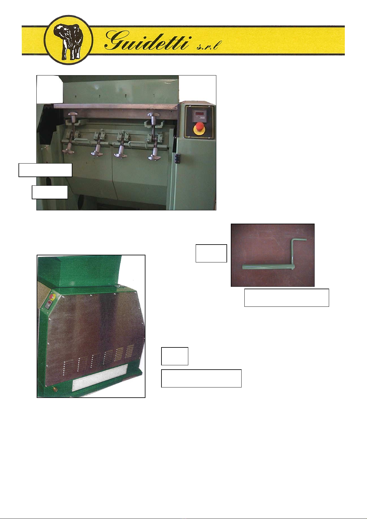
B. Unscrew the locking screw ( Page 9 - Fig. 3 ) and open the front door.
C. Open the rear door ( Page 9 - Fig. 4 ).
D. Remove the unloading hopper.
E. Slacken the two knobs and open the grid’s support. Support the grid’s support with one hand in
order to place it slowly on the base.
F. Remove the grid, allowing it to slide on the support, and lift it out.
G.Remove the grid’s support.
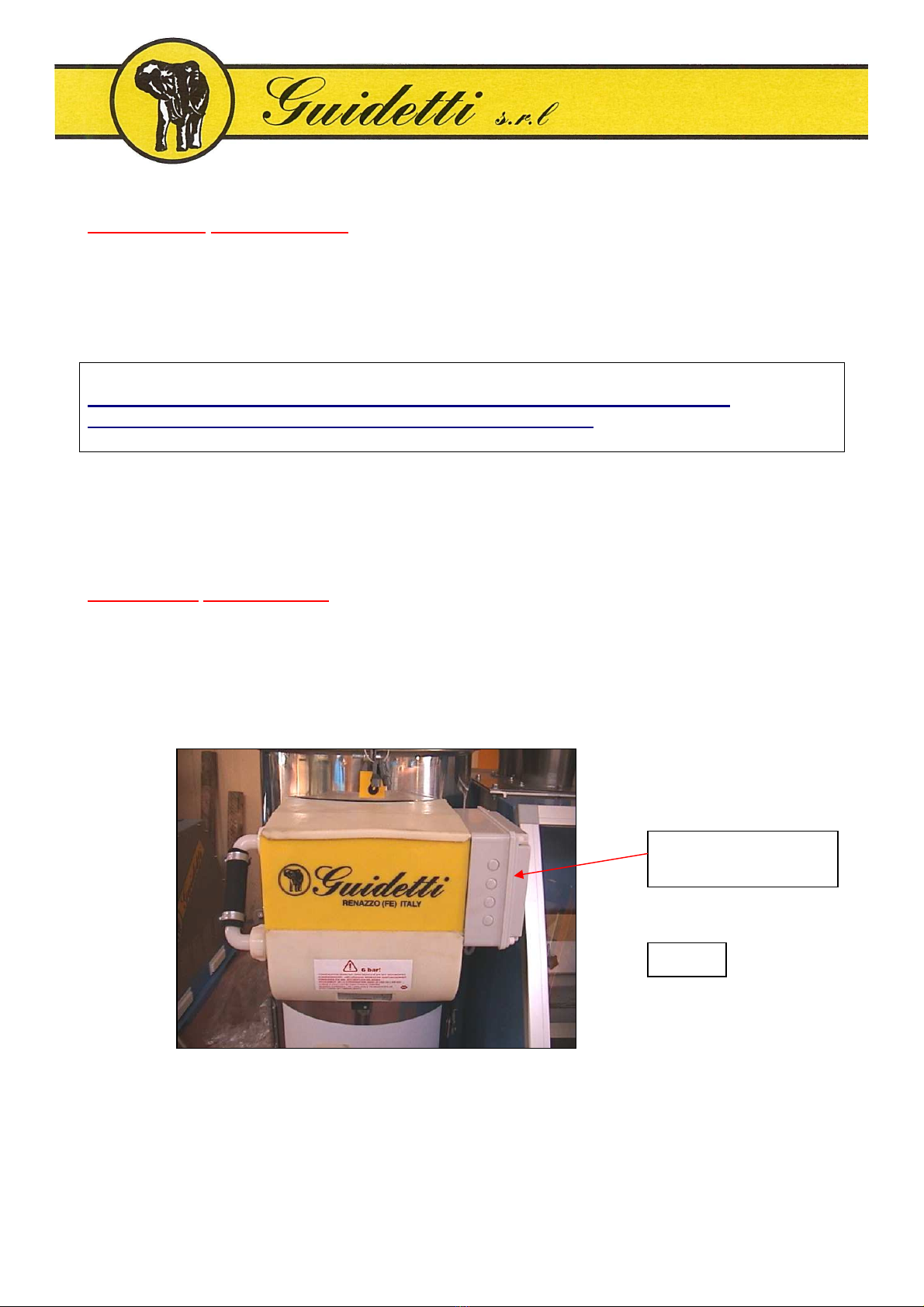
H.Open the hopper by turning the proper screw placed on the left high side of the cutting chamber
(Page10 –Fig. 6) and using the proper key supplied.
I. Check that there are no foreign bodies inside the cutting chamber.
J. Close again the hopper.
K.Assemble again the grid’s support, the grid on the support, lift the whole and tighten it by the
two knobs, taking care that the grid slides perfectly into its seats.
L. Remove the right crankcase cover ( Page 10 - Fig. 7 ) and by a manual operation on the pulley,
make one complete revolution of 360° of the rotor in the direction indicated by the appropriate
arrow. If no particular noises or friction are heard, the cutting chamber is completely free.
M. Replace the right crankcase cover .
N. Insert the unloading hopper.
O.Close the rear door by tighting the two knobs.
P. Close the front door and tight the loking screw (Page 9 –Fig. 3).
Q. Give again tension to the electric board of the machine.

- 9 -
Rear Door
Fig. 4
Fig. 3
Locking Screw
Front Door

- 10 -
After completing all the connections, check the functions of the machine and operate it idly: first
start the aspirator and then the other machines in this order: vibrator, the rotary valve, the fan and
the grinder. Switch off the machine following the reverse order: the grinder, the fan, the rotary
valve, the vibrator and the aspirator.
Switching on the power, the cleaning system of the filter starts automatically.
Wait for about 20-25 seconds, which is the time required for the electric motor to reach maximum
power.
Right Hand Cranckcase
Fig. 7
Fig. 6
Screw for hopper
Knobs
Fig. 5

- 11 -
OPERATION-ADJUSTMENT
Supply the machine with the material: holding the valve for the air adjustment open, fill the
separating table. Act upon the air valve through the switch on the electric board.
When the table will be completely covered with the material reduce the air by means of the switch
until the heavy material begins to come out from the front of the machine.
If the heavy material comes out from the rear of the machine, reduce the air; increase the air if the
light material comes out from the front of the machine .
Adjustment of the flap ( Page 12 - Fig. 9 )
The adjustment of the flap depends on the thickness of the material to process and on the quantity of
the heavy material in the product.
The height of the flap should be greater than the thickness of the material.
In order to adjust the flap, loosen the two knobs and take the flap to the height you want. At the end
of the adjustment, tighten the knobs again.
Before switching off the machine at the end of the shift or for other reasons, stop the supply of the
material to the grinder and wait a few minutes to allow the cutting chamber to crush completely the
material contained in it.
Stop the grinder and make sure that it is completely stationary before switching off the fan and the
other machines in this order: the rotary valve, the vibrators and the aspirator.
AMMATER ( Page 12 – Fig. 8 )
The ammeter is an instrument which indicates the absorption of the grinder. The measuring is
expressed in ampere “A”. The expressed value must not be superior to 67 A for a long time. Only
peaks are allowed. Reduce the loading of materials into the machine if you work with an high
degree of absorption.

- 12 -
Knobs
Flap
Fig. 9
Ammeter
Fig. 8

- 13 -
Se
paratin
g
Table
Fig. 11
Knobs
Fig. 10

- 14 -
PERIODIC CLEANING
∗Every 8 hours clean the separating table ( Pag. 13 - Fig. 10, 11 ) .
Loosen the four knobs ( Pag. 13 - Fig. 10 ) and take out the table from the front of the machine.
Clean it with compressed air or with water if the dirty is particularly sticky.
∗Empty the drawer containing the dust ( Pag. 15 - Fig. 14 ) and ensure that it is never completely
full.
The time that is necessary to fill a drawer depends on the material to process and on the quantity
of dust the material contains.
∗Periodically check the condition of the bags through the inspection door (Pag.14- Fig. 12).
∗Periodically empty the drawer which is below the suction fan of the cutting chamber and over
the hopper of the grinder.
NOTE: all these operations must be done when the machine is completely still.
Inspection door
Fig. 12

- 15 -
Dust drawer
Fig. 14
Rotary valve
for the
automatic
extraction
of the dust
Fig. 13

- 16 -
PERIODIC CHECK AND MAINTENANCE
The machine has no parts that must be lubricate or greased. It does not require any checks.
Cleaning and unblocking of the cutting chamber due to stoppage caused by foreign bodies or
parts which are too heavy.
NOTE: Before carrying out any maintenance on the cutting chamber, the operator must put on
sufficiently thick working gloves to prevent injury to hands if he accidentally touches sharp parts or
the cutting edge of the blades.
•Switch off the power to the machine and remove the fuses from the main panel.
•Open the front door.
•Open the grinder according to the procedure already described on page 8.
•Remove the grid.
WARNING: Never attempt to free a jammed machine by placing your hands on the rotor.
Use a strong wooden lever to exert force on the rotor, usually in the direction opposite normal
rotation.
If necessary, tap gently the rotor by means of a leather mallet or a rubber one.
We recommend the use of long pliers to remove the material or materials that block the rotor.
Keep in mind that the removal of material may cause rotation of the rotor.
Close the hopper. Insert the cradle that supports the grid in the appropriate shaft, supporting it on
the base of the grinder. Insert the grid making sure that it slides perfectly into the seats of the rear
slot. Lift the cradle complete with grill so as to lean perfectly the plate of the cradle on the fixed
blade holder block and tighten the blocking knobs.

- 17 -
Remove the right hand crankcase cover.
By a manual operation on the pulley, make a complete revolution of 360° of the rotor, checking that
the rotary blades do not touch the grids. If no particular noises or friction are heard, the grids have
been correctly assembled in its seats.
After clearing the jam from the bottom of the grinder, assembly the case cover protecting the pulley.
Then close the rear and the front doors.
Replace the fuses,
Turn the main switch,
Restore the red “mushroom” emergency bottom,
Start the motor of the grinder by pulling the “START-grinder” bottom.
Adjustment, re-sharpening or replacement of the fixed blades (counter-blades)
NOTE: Before carrying out any maintenance on the cutting chamber, the operator must put on
sufficiently thick working gloves to prevent injury to hands if he accidentally touches sharp parts or
the cutting edge of the blades.
•Switch off the power at the mains and remove the fuses..
•Open the front door.
•Open the grinder, according to the procedure already described on page 8.
•Remove the grid.
•Before proceeding to adjust the distance between the fixed and rotary blades, check the existing
distance with the clearance gauges. Remember that the distance is set by the manufacturer to
0,15 – 0,20 mm. for normal applications.
•If the distance between the fixed blades (counter-blades) and the rotary blades far exceeds 0,15 –
0,20 mm., a further adjustment must be made.
•Moreover, if the blades have a very rounded (blunt) cutting edge, the blades must be replaced
with sharp blades or new blades.
•To adjust the fixed blades (counter - blades), slacken the fixing screws. This applies both to the
fixed upper and lower blades.

- 18 -
•Using a single-head wrench, gently turn the adjusting screws. There are two adjusting screws to
each fixed blade.
•Insert a 0,15 – 0,20 mm. clearance gauge between the cutting edges of the rotary and fixed
blades, adjusting the screws to create the clearance required for the clearance gauge to move (see
above diagram).
•Slowly rotate the rotor, checking the exact distance, for one complete rotation, between all the
rotary blades and the fixed blades.
•Check that the distance between the fixed and the rotary blade is the same at both ends of the
blades, moving the fixed blade by means of the adjusting screws, a little at a time, but always on
both sections.
•When the adjustment has been made, tighten the screws securing each counter-blade with the
torque wrench and lock the adjusting screw lock nut.
NOTE: to avoid seizures, all the screws must be moistened with a film of lubrificating oil.
•If necessary, re-sharpen the counter – blades (they obviously need to be dismantled).
•For reassembling the re-sharpened counter-blades, use the same screws and washers as those
already used. If new counter-blades are fitted, however, replace also the screws and washers
with new ones of the same strength.

- 19 -
•Then replace the parts previously removed in reverse order, making sure that the grids slide
perfectly into the seats of the rear slot and also tightening the tie bolts securing the grid’s support
and the hopper.
•Remove the right hand crankcase cover.
•Then rotate the pulley manually, checking that there is no interference between the rotary and
fixed parts.
•Replace the right hand crankcase cover.
•Close the front door and tighten the appropriate knob.
•Close the rear door.
•Replace the fuses.
•Turn on the main switch of the electrical control board of the grinder.
Dismantling for re-sharpening or replacing the rotary blades
NOTE: Before carrying out any maintenance on the cutting chamber, the operator must put on
sufficiently thick working gloves to prevent injury to hands if he accidentally touches sharp parts or
the cutting edge of the blades.
•Switch off the power at the mains and remove the fuses. .
•Open the front door.
•Open the grinder, according to the procedure already described on page 8.
•Remove the grid.
•Rotate the rotor until the first row of rotary blades is accessible.
•Place a strong wooden lever inside the rotor to prevent it from moving.

- 20 -
•Unscrew the screws securing the blade and then remove the blade.
•Repeat the operation as many times as the rotary blades are.
NOTE: before replacing the rotary blades, it is necessary to slacken the screws securing the counter-
blades, as well as the support screws for adjustment, so that the counter-blades can be moved back
to allow space for the new rotary blades and allow free rotation of the rotor.
•When the rotary blades are removed for sharpening, it is necessary to carry out this operation on
the entire set of blades.
•The new rotary blades must all be completely replaced, otherwise good adjustment between the
fixed and the rotary blades would not be possible.
•If the blades are only re-sharpened, the same fixing screws can be used.
NOTE: all the screws must be moistened with a film of lubricating oil to prevent seizures.
•Throughly clean the seats of the rotary blades before assembling them.
•Remember always to lock the rotor with a wooden lever so that it cannot rotate dangerously.
•Tighten the screws with a torque wrench.
•Restore the correct distance between the fixed and rotary blades as previously specified.
•Then reassemble the parts previously dismantled in reverse order, making sure that the grid
slides perfectly into the seat of the rear slot, and also tightening the tie bolts securing the grid’s
support and the hopper.
•Remove the right hand crankcase cover.
•Then rotate the pulley manually, checking that there is no interference between the rotary and the
fixed parts.
•Replace the right hand crankcase cover.
•Close the front door and tighten the screws acting on the switch.
Table of contents
Popular Industrial Equipment manuals by other brands

Fröling
Fröling GAR 110 Installation and operating instructions

SMC Networks
SMC Networks EX260-VIL1 instruction manual

ABB
ABB ReliaGear ND Installation, operation and maintenance manual

turck
turck IM12-CCM03 Series quick start guide

Fraser
Fraser 3014 operating instructions

ABB
ABB HT600125 Operation manual