manuals.online logo
Brands
  1. Home
  2. •
  3. Brands
  4. •
  5. Rinnai
  6. •
  7. Water Pump
  8. •
  9. Rinnai GTK03U User manual

Rinnai GTK03U User manual

Item # Item Qty
1Hot Water Manifold 1
2Cold Water Manifold 1
3GTK03U pump and two unions 1
4Flow Restricting Bypass 1
5Flow Restrictor Bypass Adapter 1
6Grundfos Crossover Valve 1
7Control-R™ Wi-Fi Module 1
8Pipe Cover 1
• Teflon Tape
• Hot and Cold Water Isolation
Valves (supplied with water heater)
• Tankless Water Heater
Installation and Operation Manual
GTK03U Pump Kit Assembly Instructions 2
1. Remove the tankless water heater from the box and lay it flat with the front cover facing up
(Figure 1).
2. Wrap Teflon tape (field-supplied) around the threads of the cold water inlet and hot water
outlet (Figure 2).
Lay water heater flat.
Hot water
outlet
Cold water
inlet
Figure 2
Figure 1
GTK03U Pump Kit Assembly Instructions 3
3. Remove the 3/4 in. union nut from the hot water manifold (Figure 3a) and install it on the
hot water outlet (Figure 3b).
4. Install one of the pump union fittings onto the cold water inlet (Figure 4).
Figure 3a Figure 3b
3/4 in.
Union Nut
Hot water
manifold
3/4 in.
Union Nut
Hot water
outlet
Figure 4
Cold water
inlet
Pump union
fitting
GTK03U Pump Kit Assembly Instructions 4
5. Wrap Teflon tape around the top connection on the cold water manifold and install the
second pump union fitting (Figure 5).
Figure 5
Pump union
fitting
Figure 6
Pump
gasket
Cold Water Manifold
6. Connect the pump to the union on the cold water inlet, making sure the pump gasket is in
place. The arrow on the side of the pump must be pointed up towards the water heater for
correct installation (Figure 6).
GTK03U Pump Kit Assembly Instructions 5
7. Install the hot water assembly onto the union nut from step three (Figure 7).
8. Connect the cold water manifold assembly to the inlet of the pump. Ensure the pump union
gasket is in place before connecting (Figure 8).
Figure 7
3/4 in. union
nut
Figure 8
Pump union
gasket
Hot water
assembly
Cold water
manifold
assembly
GTK03U Pump Kit Assembly Instructions 6
9. Install the flow restricting bypass adapter onto the hot water manifold (Figure 9).
10. Thread the flow restricting bypass onto the hot and cold water manifolds (Figure 10).
Figure 9
Figure 10
Flow Restricting
Bypass Adapter
Flow Restricting
Bypass
GTK03U Pump Kit Assembly Instructions 7
11. Install the hot and cold water isolation valves (supplied with the tankless water heater)
(Figure 11).
12. Install the tankless water heater onto the wall and remove the front cover (Figure 12). For
detailed instructions, refer to the Tankless Water Heater Installation and Operation Manual
supplied with the tankless water heater.
Figure 11
Figure 12
Hot Water
Isolation Valve
Cold Water Isolation Valve
GTK03U Pump Kit Assembly Instructions 8
13. Route the pump power cable through the hole in the bottom of the unit and secure it from
the inside with the supplied locknut (Figure 13).
Figure 13
Secure the
pump power
cable with the
locknut
GTK03U Pump Kit Assembly Instructions 9
14. Connect the pump power cable to the water heater PC Board.
15. The wire harness for the recirculation pump is bundled with the wire harness from the PC
Board (the pump wiring is labeled to show where to connect to the tankless water heater).
The connector from the tankless water heater has a black and white wire with the label
“Cut wire to connect to pump.” DO NOT CUT THE WIRE. To connect to the pump, remove
the protective cap from the wire lead and plug the GTK03U connection into it.
Push in
tab to
remove
cap
Tankless Connections GTK03U Connections
Mated Together
16. Connect the ground wire to the body of the tankless water heater.
Ground Wire
GTK03U Pump Kit Assembly Instructions 10
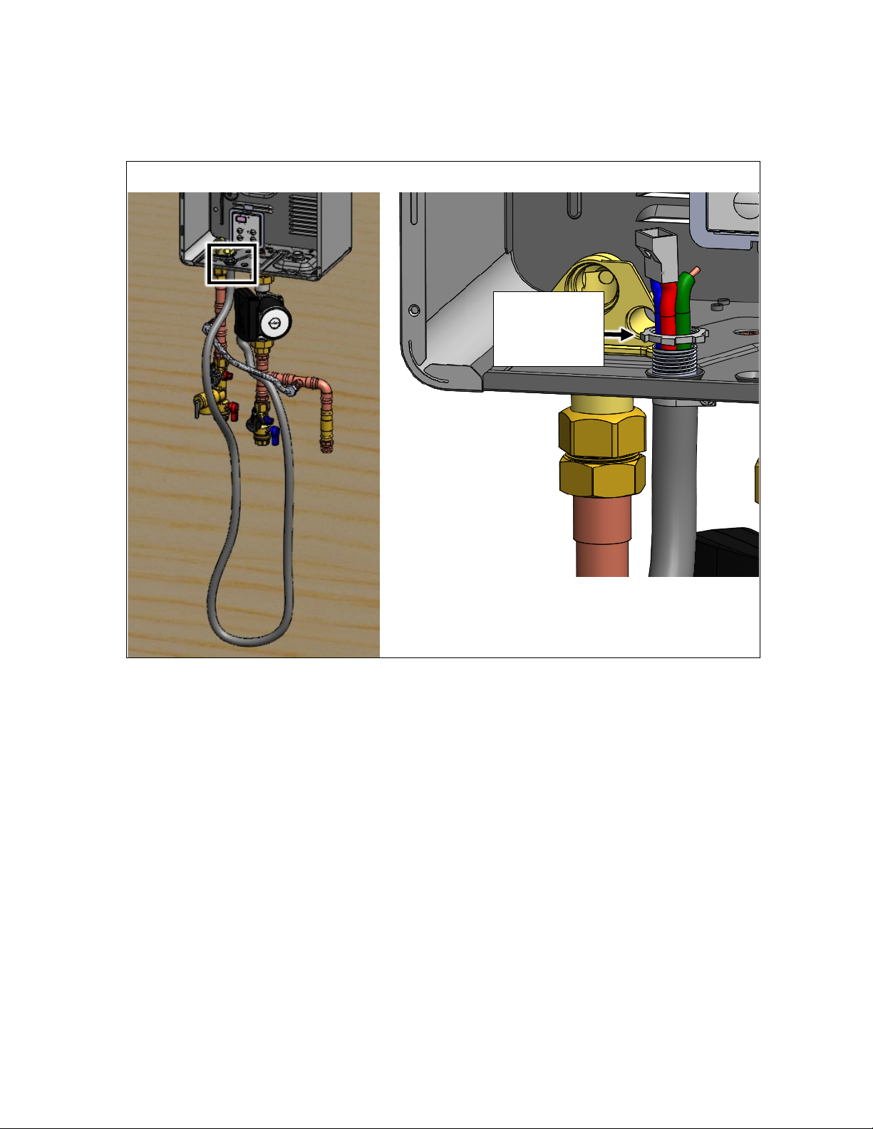
17. While the tankless water heater front cover is off, set the dip switches for recirculation.
Adjust the dip switch in the water heater by moving the 4th switch in the white set of
switches (SW2) to ON.
• For Economy Mode, set the 8th dip switch in the white set of switches (SW2) to OFF
(default).
• For Comfort Mode, set the 8th switch in the white set of switches (SW2) to ON.
NOTE: For water heaters being set between 135 and 140 degrees, you must set the 7th
switch in the yellow set of switches (SW1) to ON. If not completed when set between
these temperatures, the pump flow will not activate the water heater.
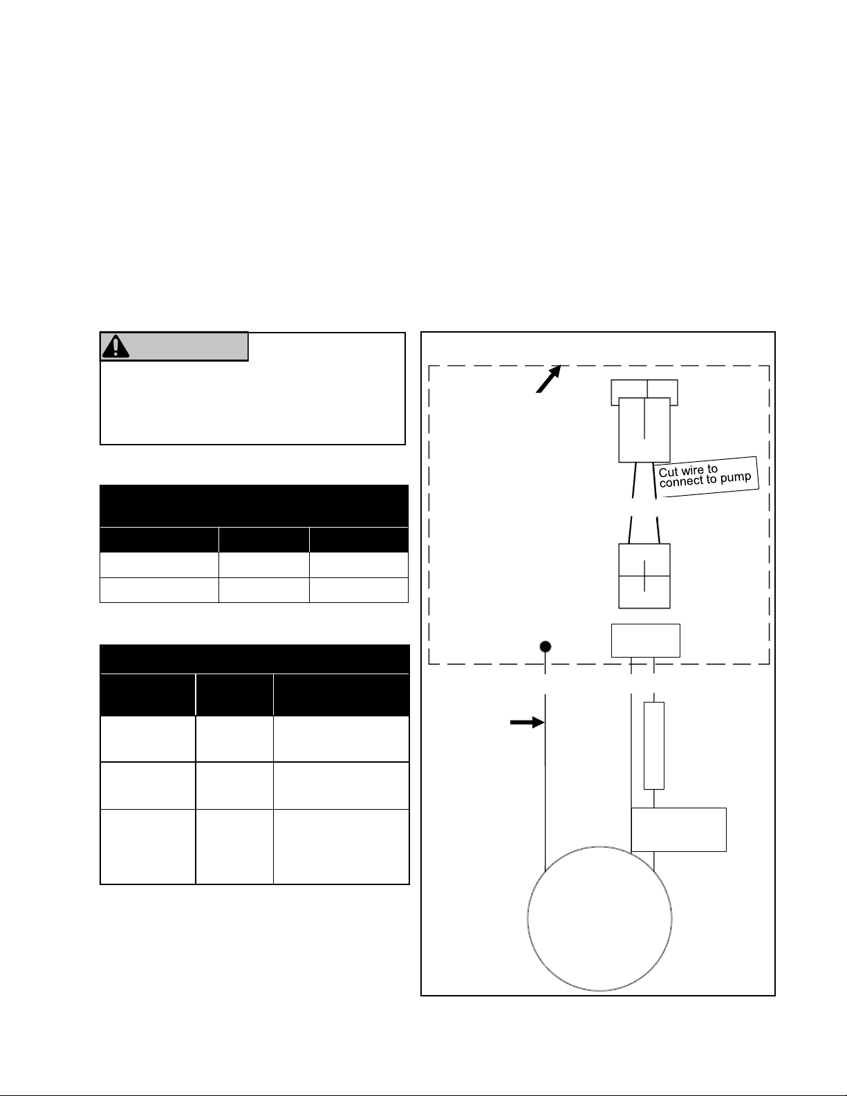
Electrical Diagram
Wiring Table
GTK03U
(Pump)
Rinnai Circ-Logic
+115VAC
(Circ-Logic)
Red (R)
with fuse Black (Bk)
Neutral
(Circ-Logic) Blue (Bl) White (W)
Ground Green
(Gn)
*Connect ground
to body of the
tankless water
heater
Settings for SW2
(Bank Of White Switches)
Switch 4 Switch 8
Economy Mode ON OFF
Comfort Mode ON ON
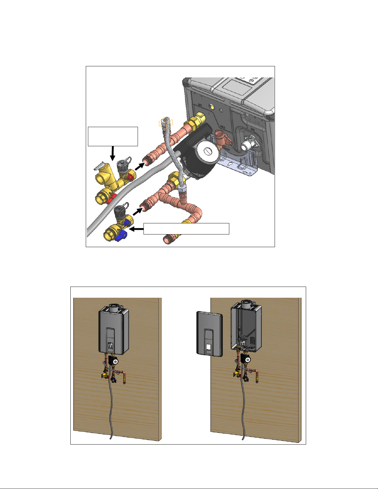
The Grundfos GTK03U Pump’s power
source is from the tankless water heater.
Disconnect this supply connection before
servicing.
WARNING RISK OF ELECTRIC
SHOCK
All Components Within
Dashed Line Inside of
Water Heater
Connect
Ground to
Tankless
Housing
2 Wire
Connector
Wire to
tankless water
heater
Fuse
GN BL R
WBK
GTK03U
Pump
GTK03U Pump Kit Assembly Instructions 11
18. Connect the Control-R™ Wi-Fi module to the terminals for controls on the PC Board.
19. Place the module wires through the bottom opening of the water heater.
20. Attach each module wire to the two screws labeled “Terminals for Controls” and partially
unscrew each of the two screws.
21. Insert the spade terminals between the screw and the contact, then tighten the screws.
Terminals
for Control
22. Reinstall the front cover onto the water heater.
23. Before connecting the water supply:
• The piping (including soldering materials) and components connected to the tankless
water heater must be approved for use in potable water systems.
• Purge the water line to remove all debris and air. Debris will damage the water heater.
• The tankless water heater must not be connected to a system that was previously used
with a non-potable water heating appliance.
• Ensure that the water filter on the water heater is clean and installed.
GTK03U Pump Kit Assembly Instructions 12
To connect the water supply, follow the instructions below.
24. Plumb the cold water supply line to the water heater on the 3/4 in. MNPT connection at the
bottom of the water heater marked “COLD.”
25. Plumb the hot water supply line to the 3/4 in. MNPT connection marked “HOT.”
IMPORTANT
Water connections to the water heater should follow all state and local
plumbing codes. Refer to the plumbing diagrams on the following pages.
Make sure the water lines to the water heater
fit within the confinements of the pipe cover.
NOTE
26. Install the pipe cover using the installation instructions included in the pipe cover box.
GTK03U Pump Kit Assembly Instructions 13
Dedicated Return Line Plumbing Diagram
Gas Supply
Cold Water Supply Line
3/4 in. Return Line
Recommended
Building Outlets
GTK03U Pump Kit Assembly Instructions 14
Crossover Recirculation Plumbing Diagram
Crossover
Valve
Hot Water Fixtures
Hot Water Supply Line
Gas Supply
Cold Water Supply Line
Install crossover valve at the
furthest fixture from the
tankless water heater.

Other Rinnai Water Pump manuals

Rinnai HJ COOPER LC Series Instructions for use

Rinnai

Rinnai HJ COOPER LC Series Instructions for use

Popular Water Pump manuals by other brands

Graco EcoQuip 2 EQm instruction manual

Graco

Graco EcoQuip 2 EQm instruction manual

Stryker IsoTour Operation manual

Stryker

Stryker IsoTour Operation manual

J&M JM0061312 manual

J&M

J&M JM0061312 manual

GORMAN-RUPP PUMPS 0 Series Installation, operation, and maintenance manual with parts list

GORMAN-RUPP PUMPS

GORMAN-RUPP PUMPS 0 Series Installation, operation, and maintenance manual with parts list

Wayne VIP15 Operating instructions and parts manual

Wayne

Wayne VIP15 Operating instructions and parts manual

DIPRA SPID'O ECC PRO 300 operating instructions

DIPRA

DIPRA SPID'O ECC PRO 300 operating instructions

KSB Evamatic-Box N Series Installation & operating manual

KSB

KSB Evamatic-Box N Series Installation & operating manual

Grundfos UPM3 instruction manual

Grundfos

Grundfos UPM3 instruction manual

T.I.P. HWW 6000 INOX NIM TLS operating instructions

T.I.P.

T.I.P. HWW 6000 INOX NIM TLS operating instructions

Sandpiper S15 Non-Metallic Service & operating manual

Sandpiper

Sandpiper S15 Non-Metallic Service & operating manual

GORMAN-RUPP PUMPS SUPER T Series T4A3S B Installation, operation and maintenance manual

GORMAN-RUPP PUMPS

GORMAN-RUPP PUMPS SUPER T Series T4A3S B Installation, operation and maintenance manual

Giant P480 Operating instructions/ repair and service manual

Giant

Giant P480 Operating instructions/ repair and service manual

AL-KO HWA 4000 comfort manual

AL-KO

AL-KO HWA 4000 comfort manual

Graco SoloTech i6 Repair and parts

Graco

Graco SoloTech i6 Repair and parts

Liberty Pumps 250-Series installation manual

Liberty Pumps

Liberty Pumps 250-Series installation manual

WITA wita UPH 20-KS TRANSLATION OF THE ORIGINAL INSTALLATION AND OPERATING INSTRUCTIONS

WITA

WITA wita UPH 20-KS TRANSLATION OF THE ORIGINAL INSTALLATION AND OPERATING INSTRUCTIONS

HNP Mikrosysteme MZR Instruction

HNP Mikrosysteme

HNP Mikrosysteme MZR Instruction

Burkert 7604 operating instructions

Burkert

Burkert 7604 operating instructions

manuals.online logo
manuals.online logoBrands
  • About & Mission
  • Contact us
  • Privacy Policy
  • Terms and Conditions

Copyright 2025 Manuals.Online. All Rights Reserved.