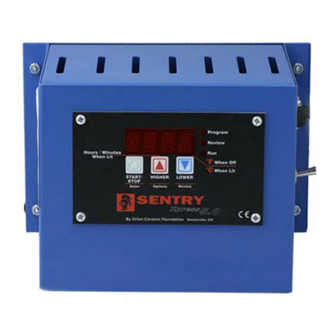
Rio Grande Digital Temperature Controller User manual

START/STOP Key
Starts and
stops a firing.
Press
after each programming
step.
Up Arrow Key
From press .Press
to select a program.
During a User Defined firing, press the
.will appear. Press . The current segment
ramp or hold number will appear. To skip, press again.
Page 6
At the display, press
.will appear. Use arrow keys to calibrate the con-
troller to fire hotter or cooler. Press to return to .
Page 9
During a User Defined firing, press
repeatedly until appears. Press .Eachtime
you press the , the hold time for the current segment
will increase by 5 minutes. Then press .Page6
During a User Defined firing,
press repeatedly until appears. Press .
Use the arrow keys to change the target temperature for the cur-
rent segment. Then press .Page6
During a firing, press repeatedly
until appears. Press . Use the arrow keys to change
the alarm temperature. Press .Tosilencethealarm,press
any key. Page 7
Down Arrow Key
From press
. The program you have
selected will appear one step
at a time. When ap-
pears, press .Page3
From
press .
Enter delay time. Press
.Page3
During firing, press
. The program you
entered will appear one step
at a time. Page 3
On during
programming.
On during
program review.
Blinks dur-
ing firing.
Indicator
Lights
Rio Grande
Digital Temperature Controller
Temperature Display
Tempera-
ture display is in °F.
Temper-
ature display is in °C.
See page 9 for instructions on
selecting °F and °C.
°F
°C Time Display : Separates
hours from minutes. Example:
Display shown above is 1 hour
and 2 minutes
Display Dot

2/
©2004, by Rio Grande IM-220/9-05
Safety
The warranty on your Rio Grande
controller does not cover damage from
overfiring, regardless of the
circumstances. It is the operator’s
responsibility to make sure the kiln turns
off at the proper time.
GWhen the kiln is not in use, disconnect the
power.
GDo not leave the kiln unattended, especially near
the expected shut-off time.
GWear firing safety glasses when looking into the
firing chamber of a hot kiln.
GDo not touch hot sides of kiln. Keep unsuper-
vised children away.
GInstall your kiln at least 12 inches from any wall
or combustible surface.
GDo not open lid or door until kiln has cooled and
all switches are off.
GFire only in a well-ventilated, covered and pro-
tected area away from combustible materials.
GKeep cordset away from hot sides of kiln or fur-
nace.
GDANGEROUSVOLTAGE!Donottouchheat-
ing elements with anything. Disconnect before
servicing.
Which Instructions Apply to
Your Controller
When you first connect the power, the controller will dis-
play these messages, one after the other:
or a software code
If your controller shows instead of a software code
before appears, then the controller includes only Skip
Segment from "Advanced Features" on pages 6 - 7. If your
controller shows a software code before appears, then
the controller has all the features in this manual.
Contents
General Guidelines . . . . . . . . . . . . . . . . . . . . 3
Time and Temperature Display . . . . . . . . . . . . . . . . . . 3
Operation Begins from the
Display . . . . . . . . . . . . . . . . . . . . . . . . . . . . . . . . . 3
Thermocouple Inspection . . . . . . . . . . . . . . . . . . . . . . . 3
A Rapid Way to Scroll Numbers . . . . . . . . . . . . . . . . . . 3
Program Review & Repeat Firing . . . . . . . . . . . . . . . . . 3
Delay . . . . . . . . . . . . . . . . . . . . . . . . . . . . . . . . . . . . . . . . 3
Power Failures . . . . . . . . . . . . . . . . . . . . . . . . . . . . . . . . 3
Selecting and Firing a PMC Program . . . . . . 4
Message: Firing Completed . . . . . . . . . . . . . . . 4
Thunder Storms and Power Surges . . . . . . . . . . . . . . . 4
Selecting a Program . . . . . . . . . . . . . . . . . . . 4
PMC Programs Stored in Memory . . . . . . . . . . . . . . . . 4
Rate . . . . . . . . . . . . . . . . . . . . . . . . . . . . . . . . . . . . . . . . . 5
Hold . . . . . . . . . . . . . . . . . . . . . . . . . . . . . . . . . . . . . . . . . 5
Temperature Over-Shoot . . . . . . . . . . . . . . . . . . . . . . . 5
User Defined Programs . . . . . . . . . . . . . . . . 5
Theory of Operation. . . . . . . . . . . . . . . . . . . . . . . . . . . . 5
Advanced Features . . . . . . . . . . . . . . . . . . . . 6
Skip Segment . . . . . . . . . . . . . . . . . . . . . . . . . . . . . . . . . 6
Add Hold Time. . . . . . . . . . . . . . . . . . . . . . . . . . . . . . . . 6
Editing the Current Segment Target Temperature
During Firing . . . . . . . . . . . . . . . . . . . . . . . . . . . . . . . . . 6
The Alarm . . . . . . . . . . . . . . . . . . . . . . . . . . . . . . . . . . . . 7
Lost Wax Burnout . . . . . . . . . . . . . . . . . . . . . 7
Error Messages. . . . . . . . . . . . . . . . . . . . . . . 8
/ Bad Programming . . . . . . . . . . . . . . . . . . . . . . 8
/ Electronics Too Hot. . . . . . . . . . . . . . . . . . . . . 8
/ Thermocouple Failure. . . . . . . . . . . . . . . . . . . 8
/ Thermocouple Reversed . . . . . . . . . . . . . . . . . 8
/ Fired Too Long . . . . . . . . . . . . . . . . . . . . . . . . 8
/ Power Failure. . . . . . . . . . . . . . . . . . . . . . . . . . . 8
/ Power Failure. . . . . . . . . . . . . . . . . . . . . . . . . . . 9
/ Thermocouple Failure . . . . . . . . . . . . . . . . . . . 9
/ Thermocouple Lag. . . . . . . . . . . . . . . . . . . . . . 9
Calibrating the Controller . . . . . . . . . . . . . . . 9
Selecting °F or °C Display . . . . . . . . . . . . . . . 9
Display Messages. . . . . . . . . . . . . . . . . . . . 10
Trouble Shooter . . . . . . . . . . . . . . . . . . . . . 10
Problem: Controller display is blank. No heat in kiln.
. . . . . . . . . . . . . . . . . . . . . . . . . . . . . . . . . . . . . . . . . . . . 10
Problem: Controller display turns on.
No heat in kiln. . . . . . . . . . . . . . . . . . . . . . . . . . . . . . . . 11
Problem: Kiln switch box ½ amp fuses keep blowing.
. . . . . . . . . . . . . . . . . . . . . . . . . . . . . . . . . . . . . . . . . . . . 11
Shorthand Instructions . . . . . . . . . . . . . . . . 12

/3
General Guidelines
Time and
Temperature
Display
Center Dot: Time
A center dot appears during
time display. It separates
hours from minutes. (Example: 1 hour, 30 minutes displays
as 01.30.) During temperature display, the dot disappears.
Single Right-Hand
Dot: °C
When temperature is
displayed in °C, a dot
appears in the lower
right. In °F display, it
disappears. You can
choose between Fahr-
enheit and Celsius dis-
play. See page 9.
Operation Begins from the
IdLE Display
must appear before you can fire the kiln.
IIf , , or other message appears instead of
when the kiln is first turned on, press the
key (the key with the circular arrow). will appear.
IIf you press during a firing, will appear. To
get back to , press again.
IIf the display shows an error message such as in-
stead of , see page 8.
I(firing completed) appears at the end of a firing.
To make appear, press .
Thermocouple Inspection
The small rod protruding into the firing chamber is the
temperature sensor, or thermocouple.
Caution: Bumping the thermocouple can push it
out of the firing chamber. This could cause an
overfire!
IA 1/8” diameter thermocouple should extend into the fir-
ing chamber ½” - 58”.
IA ¼” diameter thermocouple should extend into the fir-
ing chamber 1” or more.
IKeep shelves, posts and ware 1” - 1 ½” away from the
thermocouple.
A Rapid Way to Scroll Numbers
During programming, hold an arrow key down several
seconds, and numbers willbegin to scroll rapidly. Ordinarily,
you would press to raise a number and
to lower it. But sometimes it is faster to press the
opposite key. This is because the numbers scroll below 0000
to the highest number, and vice versa. Examples:
ITo program a 99.59 hour Hold when the display shows
00.00, press the once.
ITo program a FULL rate when the display shows 0000,
press the once.
ITo program a temperature of 200°F when the display
shows 1800°F, press the . That is faster than
pressing the .
Program Review & Repeat Firing
Program Review lets you check that the information pro-
grammed into the controller is correct. Program Review
shows the values for the program in active memory. Use Pro-
gram Review from to repeat the last program you
fired.
IPress the
key. The rate, temperature, hold, etc.
will display one after the other. Firing will continue.
I
Press the key. After rate, temper-
ature, hold, etc., will appear. Press .
will appear, and the kiln will begin firing the program just
reviewed.
Delay
Delay is a count-down timer. The kiln begins firing when
the timer runs out of time. Use Delay to fit a firing into your
schedule.
Caution: For safety, do not leave the kiln alone dur-
ing a delay or a firing. We cannot guarantee your kiln
against overfiring even though the controller is au-
tomatic.
After you have selected a program and the controller
is ready to begin firing, will appear.
Press the key once. will ap-
pear, alternating with .
Use the arrow keys to enter delay time. (The decimal
separates hours and minutes. Example: 1 hour 10
minutes = 01.10) Then press twice.
will appear, alternating with time left until the firing
begins.
Note: Press during delay to end the delay
and begin the firing. The maximum delay is 99
hours and 59 minutes.
Power Failures
After a power failure, the controller will continue firing
provided that:
IThe kiln temperature is above 212°F/100°C when the
power comes back on.
IThe temperature dropped no more than 180°F/100°C
while the power was off.
°F
°C

Program 4: PMC Original
Heating rate per hour: Full
Temperature: 1650°F
Hold: 2 hours
Program 5: PMC Gold
Heating rate per hour: Full
Temperature: 1830°F
Hold: 2 hours
Program 6: User Defined program
Program custom rates, temperatures, and hold times.
Selecting and
Firing a PMC
Program
From , press .
Press the key (not the
). Each time you press the , a dif-
ferent program will appear:
PMC Plus Fast
PMC Plus Slow
PMC3 Slow
PMC Original
PMC Gold
User Defined custom programming
When the PMC program you want appears, press
. will appear. Press to begin
firing. will appear and the Run indicator light
with begin blinking. The kiln is now firing.
To stop a firing before completion, press .
will appear, alternating with kiln temperature.
Note: Do not be concerned if your kiln makes a
clicking sound during firing. Kilns use relays to
power the elements. The relays click each time their
electrical contacts come together.
Note: The kiln’s actual firing rate may be less than
the rate you programmed, depending on the kiln
model, available voltage, and density of load you are
firing.
When the kiln fires to completion, it will beep for 30 sec-
onds. The display will show the following:
IFiring time
IPresent temperature
I(fired to completion)
To return to , press .
4/
Power Failure Messages
The power failed during a cooling segment, and
the kiln cooled past the target temperature while the power
was off.
The power failed during firing and kiln tempera-
turewas below212°F/ 100°Cwhenthe powercameback on.
The power failed during firing and temperature
dropped more than 180°F / 100°C by the time the power
came back on.
CPLT Message:
Firing Completed
When the firing has success-
fully completed, the controller
will shut off power to the elements and sound an alarm for 30
seconds.Then threemessages willcycle oneafter theother:
(complete)
Firing time in hours and minutes
The current kiln temperature
Thunder Storms and Power Surges
Unplug the kiln or disconnect the power when the kiln is
not in use, especially during thunder storms and in areas
with frequent power surges. If the kiln is part way through a
firing when a storm begins, it is probably okay to continue
the firing with close supervision. Do not leave the kiln unat-
tended.
Selecting a
Program
PMC Programs Stored in Memory
Five PMC programs are stored in memory. You can also
program custom firings. Shown below are the heating rate,
temperature, and temperature hold time for each stored
program. (See “Theory of Operation,” next page, to learn
more about rate, temperature, and hold.)
Program 1: PMC Plus Fast
Heating rate per hour: Full
Temperature: 1650°F
Hold: 10 minutes
Program 2: PMC Plus Slow
Heating rate per hour: 1500°F
Temperature: 1470°F
Hold: 30 minutes
Program 3: PMC3 Slow
Heating rate per hour: 1500°F
Temperature: 1110°F
Hold: 45 minutes

/5
Rate
Each segment must include a rate, which is degrees of
temperature change per hour.
Thekilnwillfireatfullpowerwhentherateis
1799°F/999°C. Full power displays as .
Note: To enter full power from , press the
key once.
Hold
Hold is the length of time that you want the kiln to remain
at the target temperature. Hold is also called soak or dwell
time. Hold maintains a steady temperature for the length of
time you specify. You can use Hold in both heating up and
cooling down segments.
When Hold is set to 99.59 hours, the controller will re-
main at that temperature indefinitely, until you press .
To enter a 99.59 hour Hold, press the once
from 00.00 during programming.
Note: During firing, the display shows Hold tem-
perature and time left in Hold.
Temperature Over-Shoot
When a kiln is heated too fast, it may over-shoot the target
temperature, especially in small kilns at lower temperatures.
To avoid this, add an extra segment in a User Defined pro-
gram to slow the firing.
User Defined
Programs
Theory of Operation
The temperature you are firing to is called the target tem-
perature. After the controller reaches the target tempera-
ture, it can also hold that temperature.
The controller fires at a controlled heating rate. The rate
is figured in degrees per hour. If you selected a rate of 100°
per hour, it would take 10 hours for the kiln to reach 1000°.
Rate is similar to “miles per hour.”
In summary, the controller does three basic tasks:
1) It fires at a controlled heating rate, or speed, measured
in degrees of temperature change per hour.
2) It fires to a target temperature.
3) It can hold the target temperature.
The controller fires in segments, or stages. A segment is a
given heating rate to a target temperature. Shown above is a
segment with a target temperature of 1250° and a rate of
625°, with a hold of one hour.
Heating rate is figured in degrees per hour. The recom-
mended heating rate for the material you are firing is usually
available from your supplier. It also varies depending on the
thickness of the material.
To figure how long a firing segment will take, subtract the
current temperature from the target temperature and divide
the resultant temperature by the heating rate. In the diagram
above, the firing time is 1250° - 80° (room temperature) =
1170 ÷625 = 1.87 hours.
The controller can fire up to 8 segments per firing in a
User Defined program. One segment is often all that is
needed, though.
After the controller has finished firing the last segment of
a User Defined program, it will turn off power to the kiln.
Note: If you enter a rate of 0000 in segment 1, or if
the target temperature in segment 1 is lower than
the current temperature, will appear in the
display.

6/
User Defined
Programming
Instructions
Note: You have up to 8 segments available in a User
Defined program. If you don’t need all 8, zero out
the unused segments. See step 6 below.
From , press .
Press the key (not the
). When appears, press . (Ig-
nore - .)
will appear. Enter firing rate (temperature
change per hour) for segment 1. (1° = slowest rate.
1799°F/999°C = full power.) Then press .
or and the target temperature from the
last firing will appear. Use the arrow keys to change
the temperature. Then press .
andthe hold timefrom thelast firing willap-
pear (Example: 1 hour 10 minutes = 01.10). Use
the arrow keys to change the hold time. Then press
. (No hold = 00.00.)
Continue entering values for the segments needed.
When appears for the next segment that you
don’t need, select 0000. Then press . This
will zero out the remaining segments. (Example:
You need only 1 segment. When appears, en-
ter 0000.)
will appear. Press to begin firing.
will appear and the Run indicator light with
begin blinking. The kiln is now firing.
To stop a firing before completion, press .
will appear, alternating with kiln temperature.
Note: Do not be concerned if your kiln makes a
clicking sound during firing. Kilns use relays to
power the elements. The relays click each time their
electrical contacts come together.
Note: The kiln’s actual firing rate may be less than
the rate you programmed, depending on the kiln
model, available voltage, and density of load you are
firing.
When the kiln fires to completion, it will beep for 30 sec-
onds. The display will show the following:
IFiring time
IPresent temperature
I= Fired to completion
To return to , press .
Advanced
Features
Note: All the features in this section are available in
a User Defined program. The alarm is the only fea-
ture in this section that is available in a PMC pro-
gram. This is because PMC programs cannot be
altered.
Skip Segment
Skip Segment works only during a User Defined firing. It
jumps the firing from the current segment to the next one.
During firing, press the .
will appear.
Press . The current segment ramp or hold
number will appear.
Press again. (If you change your mind and
don’t want to skip that segment, don’t press
after appears. The firing will continue in the
same segment and the temperature will appear af-
ter one minute.)
Skip Segment skips to the ramp of the next segment from
either a ramp or hold of the current segment. (Skip Segment
does nothing during the final segment. To end the final seg-
ment, press .)
Skip Segment Example
You have pro-
grammed 1425°F for glass fusing, followed by a segment for
controlledcooling. Watchingthe glass throughthe peephole,
you notice that the glass edges have rounded nicely at 1315°.
Use Skip Segment to end the firing segment and to begin the
one for slow cooling.
Note: Make a note of the temperature at which the
glass fused. Program that temperature for the next
firing of that type of glass.
AddHoldTime
Add Hold Time works only during a User Defined firing.
It adds 5 minutes to a hold. It is designed for ceramists who
watch witness cones and for glass artists who inspect the
glass near the end of firing.
During a firing, press the repeatedly
until appears.
Press . The hold time for the current seg-
ment will appear.
Press the . Each time you press the
, the hold time will increase by 5 minutes.
Press .Thenormal temperaturewillappear.
Note: Add Time will add 5 minutes to a hold even if
no hold had been programmed.

/7
Editing the Current Segment Target
Temperature During Firing
While the kiln is firing a User Defined program, you can
change the target temperature of the current segment. You
can edit only the segment that is firing. So if the first seg-
ment is the current one, you can edit only the first segment.
To edit other segments, wait until the firing has progressed
to those segments.
Even if the current segment has already started its hold
time, you can still edit the segment's target temperature. You
can raise or lower the target temperature. The controller will
go back out of hold and fire to the new target temperature at
the original rate. (You cannot edit the rate, however.)
During a firing, press the repeatedly un-
til appears.
Press . The target temperature for the current
segment will appear.
Use the arrow keys to changethe target temperature.
Press . The normal kiln temperature will ap-
pear.
The Alarm
The alarm works in both PMC and User Defined pro-
grams.
While the kiln is firing, you can set the alarm, which
sounds when the kiln reaches the alarm temperature. Use
the alarm to alert you to check the fusing or slumping of
glass.
You can enter only one alarm temperature at a time. How-
ever, after the alarm beeps, you can set the alarm for another
temperature, as many times as you want, during the firing.
Entering an alarm temperature automatically erases the pre-
vious alarm temperature.
Note: The alarm temperature that you set during a
firing must be higher than the current display
temperature.
During a firing, press the repeatedly un-
til appears.
Press . The current alarm temperature will
appear.
Use the arrow keys to changethe alarm temperature.
Press . The normal kiln temperature will ap-
pear.
To silence the alarm, press any key.
Analarm temperatureof32°F /0°C willturnoff thealarm.
Lost Wax Burnout
Caution: Only kilns with vent holes are designed
for lost wax burnout. However, you can use a kiln
without the vent hole provided that you open the
door ½” during venting.
Caution: Always use a wax tray.
Note: These instructions apply to injection wax that
melts at 200°F, not pattern waxes and plastics that
melt at higher temperatures. If smoke appears dur-
ing wax elimination, turn off the kiln. Smoking wax
means the kiln fired hotter than 300°/148°C.
Overview
Lost wax casting is the process of carving a shape in wax,
making a mold, and then casting that shape in metal. After
the wax has been carved, a mold is made of the wax shape.
The mold is a negative image of the wax. The wax is later
melted out of the mold through hollow channels called
sprues.
Lost wax burnout is the process of preparing a casting
mold for the melted metal that will be poured into it. The
steps in lost wax burnout:
Melt the wax from the mold.
Remove wax from the kiln before raising the temper-
ature higher than 300°F/148°C.
Harden the mold at high temperature.
Maintain the mold at the casting temperature recom-
mended for the type of metal that will be poured into
the mold.
Caution: Prevent wax or carbon from contacting
the kiln’s walls and elements. Carbon build-up in-
side a kiln ruins the interior. Carbon conducts elec-
tricity and causes elements to short circuit. Damage
to elements from contact with foreign materials is
not covered by warranty.
A Sample Program
Rate Temp.
Segment °F/°C °F/°C Hold
1 500/277 300/148 01.00
2 500/277 1350/732 01.00
3 450/250 800/426 02.00
Segment 1 heats the wax to 300°F/148°C and holds it for
one hour, allowing it to drip from the mold.
Segment 2 hardens the mold.
Segment 3 lowers temperature to 800°F/426°C, the typi-
cal casting temperature for silver. (Most types of gold cast at
900°F/482°C.)
Note: Casting temperature depends on the size of
the mold. The temperatures above are only a guide.

8/
See your jewelry supply dealer for temperature
recommendations.
Burnout Instructions
Place a metal tray inside the kiln on three ½” posts.
Place the mold on a wire mesh screen on top of the
tray. The mold’s sprue hole should be down. The
tray will catch melting wax as it drips from the sprue
hole.
Keep the kiln’s vent hole(s), if any, open during wax
elimination. If the kiln has no vent hole, leave the
door open ½”. This allows fumes to escape from the
kiln. Heat the kiln to 300°F/148°C and hold it at that
temperature for at least one hour.
Note: Do NOT heat the wax above 300°F/148°C.
Hold at 300°F/148°C for at least one hour. During
this hour, the wax will melt from the mold and drip
into the tray. If the kiln gets hotter than
300°F/148°C, the wax may smoke and deposit car-
bon inside your kiln, causing expensive damage.
After one hour at 300°F/148°C, open the kiln. Re-
move the mold and wax tray. Pour the wax from the
tray and leave the tray out of the kiln until your next
wax elimination. (Do notleave the tray in thekiln!)
Heat the mold to the temperature recommended by
your jewelers’ supply house where you purchased
the mold material. This is usually around
1350°F/732°C.
Lower the temperature to the casting temperature
of the metal. Hold at that temperature until you are
ready to begin casting. Remove the mold with tongs.
Wear protective gloves and safety glasses.
Saving a Carbon-Damaged Kiln
If you follow the above directions, your kiln should be safe
from wax damage. In some cases, a small amount of carbon
may form on the walls over a period of time. This is due to the
burning of wax residue that was left in the mold. For this rea-
son we recommend that you periodically fire the kiln to
1500°F/815°C as follows:
Open the vent cover(s) or leave the door ajar ½”.
Fire the kiln empty to 1500°F/815°C at a rate of
300°F/166°C with a one hour hold (01.00).
Error Messages
bAdP / Bad Programming
The kiln will not fire the because the User Defined pro-
gram just entered has 1) a rate of 0000 in segment 1, or 2) the
target temperature in segment 1 is lower than the current
temperature.
EtH / Electronics Too Hot
The temperature of the electronic circuit board is above
185°F/85°C. This could damage the controller, so the firing
has been stopped. To prevent this, keep the firing room
cooler. Use better ventilation.
FaIL / Thermocouple Failure
The thermocouple, or temperature sensor, failed during
firing. Causes:
IDefective thermocouple or disconnected/loose wires
IDefective controller
IElectrical noise
Thermocouple Paperclip Test
Check the thermocouple wire
connections. (See your kiln in-
struction manual.) If connections
are tight, perform this test:
UNPLUG the kiln or disconnect the power. Re-
move the controller. Remove the two thermocouple
wires from the back of the controller.
Cut a thin paperclip in half. Insert a U-shaped
paperclip piece, or other piece of thin wire, where
you removed the thermocouple wires.
Plug in the kiln. If the controller displays room tem-
perature, replace the thermocouple. If it shows
, replace the controller.
tCR / Thermocouple Reversed
Thermocouple lead wires are reversed. Check that the
thermocouple lead wires are connected to the correct termi-
nals. See your kiln's wiring diagram.
FtL / Fired Too Long
This message appears when both of the following condi-
tions are met:
IThe temperature rise is less than 27°F/15°C per hour
IThe firing is 2 hours longer than programmed
See “Controller turns on. No heat in kiln,” page 11.
PF 1 / Power Failure
The power failed during a cooling segment, and the kiln
cooled past the target temperature while the power was off.
The kiln will not resume firing. To return to the dis-
play, press any key.

/9
PF 2 / Power Failure
The power failed during firing and kiln temperature was
below 72°F / 40°C when the power came back on. The kiln
will not resume firing. To return to the display, press
any key.
PF 3 / Power Failure
The power failed during firing and temperature dropped
more than 180°F / 100°C by the time the powercame back on.
The kiln will not resume firing. To return to the dis-
play, press any key.
tC / Thermocouple Failure
The thermocouple failed during the display. See
the "paperclip" test under "FaIL," page 8.
tCL / Thermocouple Lag
The heating rate is slower than 9°F / 5°C per hour and the
kiln temperature is more than 100°F / 56°C away from the
programmed temperature. To return to the display,
press any key. Causes:
IOn kilns that use a portable controller, the thermocouple
fell out of the firing chamber.
IA bare spot on the thermocouple lead wires has touched a
grounded object inside the kiln switch box causing the
thermocouple to short out.
Iwill flash if you program a cooling segment tem-
perature that is below room temperature.
Check for worn or burned out elements, defective relays,
low voltage and defective thermocouple.
Calibrating the
Controller
You can calibrate the controller to fire up to 20°F/11°C
hotter or cooler than the zero factory setting.
From , press the key. After
rate, temperature, hold, etc., will appear.
With shown in the display, press the
key.
will appear. Press the arrow keys to change the
controller temperature. (Lower numbers include a
"-".)
Press the key to return to the display.
To fire the controller, press . will ap-
pear. Or to return to , press two more
times.
Selecting °F or °C
Display
The controller can display temperature in either °F or °C.
If your controller shows a small display dot in the lower right
corner of the display, the temperature shown is °C. No dot
means °F. To change temperature display:
UNPLUG kiln or disconnect power.
Remove the four screws that hold the controller to the
frontofthe kiln.Carefully removethecontroller from
the kiln. Leave wires attached to the controller.
Look at the back of the controller. You will find a set
of connector pins near the bottom labeled “C/F.”
When a jumper is placed on the C/F pins, the display
reads °F. When the jumper is removed, display reads
°C. Remove or insert the jumper as desired. (You can
purchase the jumper from a computer supply store if
necessary.)
Install the controller being careful not to jar compo-
nents on the back of the controller against the kiln
case.
The C/F jumper terminal is on the back of the controller, circled above.

Display Messages
The firing was stopped.
(Page 7) Ready for you to enter an alarm temperature.
When the kiln reaches that temperature, the alarm will sound.
During a User Defined firing, you can change the tar-
get temperature of a segment without having to first stop the
firing.
Fired to completion. If the kiln is already hotter than the
programmed target temperature when you begin firing,
will appear immediately after you begin firing.
(page 3) Delay is a count-down timer that starts the
kiln when the time runs out.
or (and temperature) (page 6) The target
temperature (the temperature that the kiln will fire to). Each seg-
ment in a User Defined program has a target temperature.
Full power firing rate. At this setting the kiln will fire at
its fastest rate. To select Full power, select a rate of
1799°F/999°C at the prompt in a User Defined program. A
fast way to do this is to press the key once from
. will appear.
(pages 5 & 6) Hold time of a segment, shown in hours
and minutes. (i.e. 2 hours 15 minutes = 02.15.)
(Page 7) During a User Defined firing, you can extend
the hold time to a segment without having to first stop the firing.
(page 3) The controller is ready for you to enter a pro-
gram or to begin a repeat firing.
Firing has begun. A moment after appears, you
will hear the relay(s) clicking.
, , , , (page 4)
These are PMC programs stored in memory.
(User Defined Program) (page 5) Select this option to
program a custom firing.
, , etc. (Rate) (page 6) This appears in User
Defined programming for each segment. 1, 2, etc. are segment
numbers. Enter the rate of temperature change for that seg-
ment. Rate is figured in degrees of temperature change per
hour. Example:
A temperature rise of 100° in two hours = 50° rate.
A temperature drop of 200° in one hour = 200° rate.
(Skip Step) (page 5) This message appears when you
press the key during a User Defined firing. If you press
the key again, the firing will skip to the next segment.
The firing was stopped by pressing .
The "Ready to Start" message appears after program-
ming a firing. Press to begin firing. Controller Calibration
(press the ) and Delay (press the )
are accessed from the message.
(Page 9) Calibrate the controller to fire hotter or
cooler.
Trouble Shooter
Problem: Controller display is blank.
No heat in kiln.
IIs the kiln connected to the power?
IHas the circuit breaker tripped or fuse blown?
IIs power reaching the wall receptacle?
Test with a voltmeter or test light if you are not sure.
IHas the kiln switch box ½ amp fuse blown?
The kiln’s ½ amp fuse is lo-
cated in the kiln switch box. Re-
move by pressing the fuse holder
and turning counter-clockwise
half a turn. Check the fuse by
placing the probes of an ohmme-
ter on the ends of the fuse. If the
ohmmeter reads less than an
ohm (digital meter) or reads 0
ohms (analog meter), the fuse is
okay. If the reading is OPEN (digital meter) or infinity/no
needle movement (analog meter), the fuse is bad. Replace-
ment fuse:
AGC 1/2 A 250V AC
IIs the controller receiving power? Test the power IN-
PUT connections on the back of the controller with a
voltmeter.
Controller Power Input Test
Unplug the kiln. Remove the 4
screws holding the controller
faceplate to the switch box. Lift
faceplate out of box and let the
board hang on the box with the
back of the board facing you.
Plug the kiln back in. Touch volt-
meter probes (in AC mode) to
both INPUT connections (the
white and orange wires).
Caution: Do not let the back of the board touch a
grounded object. Make sure the voltmeter is in the
AC mode when placing the probes on INPUT con-
nections.
Controller Power Input Test Result: No voltage
UNPLUG kiln. Check the switch box for disconnected
wires between the cord, transformer, and controller. If wir-
ing is okay, replace the transformer.
Controller Power Input Test Result: 20 - 24 volts AC
Correct current is reaching the board from the trans-
former. But since the board is not lighting up, it is probably
defective. Return the controller for repair or replacement.
Controller Power Input Test Result: less than 20 volts
Did you recently replace the transformer? It may be the
wrong voltage. The voltage is below 20, which is not enough

/11
power for the controller. To find out the cause of low voltage,
continue below:
Controller Input Test #2
The back of the board is
still facing you and the kiln is
plugged in. Remove the IN-
PUT plug, which is the
white, orange, and blue
wires, from the back of the
controller. Touch a voltmeter
probe to the white wire and
the other probe to the orange
wire.
Input Test #2 Result: Less than 20 Volts AC
There are two possible reasons: 1) Low voltage at the wall
receptacle; 2) defective transformer. If wall receptacle volt-
age is correct, replace the transformer.
Input Test #2 Result: 20 - 24 Volts AC
The transformer is sending correct voltage to the control-
ler. Yet when the INPUT plug was connected to the control-
ler, voltage was less than 20. This means the controller is
draining the voltage and may be defective. Return the con-
troller for repair or replacement.
Problem: Controller display turns on.
No heat in kiln.
IIs the relay making its normal clicking sound?
Yes, the relay is clicking.
Test the elements with an ohmmeter:
Element Resistance Test
UNPLUG kiln/disconnect the power. Open the
kiln’s switch box. Make sure the wires connecting the
relay to the elements are secure. If connections are
okay, continue to step 2:
Touch the ohmmeter leads to the two element con-
nectors of each element. A no-needle-movement
reading on an analog meter, or OPEN on a digital me-
ter, indicates a broken element.
If the elements check out okay, replace the relay.
Note: To replace relay, see your kiln’s instruction
and service manual.
No, the relay is not clicking.
We know the controller is receiving voltage, because the
display is lit. But the voltage from the transformer may be too
low to power the relays. Perform the “Controller Power In-
put Test,” page 10. If your controller passes the input test,
perform the “Controller Power Output Test”:
Controller Power Output Test
Is the controller sending voltage to the relay? Test OUT-
PUT with a voltmeter:
UNPLUG the kiln/disconnect the power. Remove
the 4 screws holding the controller faceplate to the
switch box. Lift faceplate out of box and let the con-
troller hang on the outside of the box with the back of
the board facing you. Then plug the kiln back in. Pro-
gram the controller to fire to 1000°F at FULL rate in
User Defined program mode. Press .
Put the voltmeter in DC mode. (It must be in DC
mode when testing OUTPUT voltage.) Touch
probes to the red wire and black wire connections.
Measure voltage when the relay clicks on.
Output Test Result: No voltage at red and black wires
The controller is not sending power to the relay. Return
the controller for repair or replacement.
Output Test Result: 10 - 14 v. at red and black wires
The controller is sending correct power to the relay. Un-
plug kiln/disconnect power. Remove the kiln switch box.
Look for disconnected wires between the controller, relay
and elements. Check the wiring diagram to be sure wires are
connected to the correct terminals. Be sure connections are
tight. If the wiring is okay, replace the relay.
Note: To replace relay, see your kiln’s instruction
and service manual.
Problem: Kiln switch box ½ amp
fuses keep blowing.
IWhat size fuse are you using? Correct fuse:
AGC ½ A 250V AC.
Ifthefuseisthe correctsize, perform thefollowing test:
Kiln Switch Box ½ Amp Fuse Power Test
UNPLUG the kiln/disconnect the power. Remove
the 4 screws holding the controller board faceplate to
the switch box. Lift faceplate out of box and let the
board hang on the outside of the box with the back of
the board facing you. Then plug the kiln back in. Dis-
connect both wire plugs
from the back of the con-
troller. Apply power to
kiln. If fuse blows, re-
place the transformer. (If
the fuse does not blow,
the problem is a board or
relay. Go to step 2.)
Connect the INPUT plug (orange, blue, and white
wires) to the board again. Leave off the OUTPUT
wire plug (the one with the red, green and black
wires). Program the controller to fire to 1000°F at
FULL rate in User Defined firing mode. Press
. If the fuse blows, replace or service the
board. (If the fuse does not blow, the problem is
causedby a shortin thecoil of arelay. Gotostep 3.)
UNPLUG kiln/disconnect power. Reconnect the
OUTPUT wire plug. Reinstall the board in the
switch box. Replace the relay.

12 /
Shorthand Instructions
To avoid confusion, read the manual before using thesequick shorthand instructions. After pressing the keys in the left col-
umn, the message in the center will appear.
Selecting a Stored PMC Program
Keys to Press Shown in the Display
through
(Not Down Arrow) (SelectProgram1,2,3,4,or5)
The kiln is now firing.
The User Defined Program
Keys to Press Display
through
(Not Down Arrow) Select PrO6
Enter Segment 1 Rate (Sample rate)
or
Enter Temperature (Sample temperature)
Enter Hold Time (Or hold time)
First segment not needed: enter a rate of 0000.
The kiln is now firing.
Table of contents
Other Rio Grande Temperature Controllers manuals
Popular Temperature Controllers manuals by other brands

Greenheck
Greenheck Vari-Green Control 475573 Installation, operation and maintenance manual

Elotech
Elotech R 1120 Description and Operation Manual

Thermo Scientific
Thermo Scientific ADVANCED Series manual

Ropex
Ropex RESISTRON RES-440 Replacement instructions

ECR International
ECR International ARGO DPM-2 Installation, operation & maintenance manual

Honeywell Home
Honeywell Home PROSiXTEMP Quick installation guide