Rion KS-16F User manual

INSTRUCTION MANUAL
PARTICLE SENSOR
KS-16F
3-20-41 Higashimotomachi, Kokubunji, Tokyo 185-8533, Japan


i
Organization of this manual
This manual describes the features and operation principles of the light-
scattering type liquid-borne particle sensor KS-16F. In sections related to the
configuration of a measurement system comprising the KS-16F and other
equipment, this manual also touches upon operation of the other equipment,
but to assure safe and correct operation, always consult the documentation of
the other equipment as well.
This manual contains the following sections.
Outline
Gives basic information on the unit.
Controls and Features
Briefly identifies and explains all parts of the unit.
Preparations
Describes how to make sampling tube, purge gas, and sample fluid
connections and how to set the unit up for use.
Measurement
Describes the basic steps and procedures for measurement.
Maintenance
Describes how to clean and prepare the unit for storage, how to replace
a fuse, etc.
Serial Interface
Explains the functions and commands of the serial interface.

ii
* All company names and product names mentioned in this manual are
trademarks or registered trademarks of their respective owners.
Multi-point Monitoring System
Explains the basics of setting up a multi-point monitoring system
using the Rion multi-point interface.
Specifications
Lists the technical specifications of the unit.

iii
FOR SAFETY
In this manual, important safety instructions are specially marked as shown
below. To prevent the risk of death or injury to persons and severe damage to
the unit or peripheral equipment, make sure that all instructions are fully
understood and observed.
Caution
WARNING
Important
Disregarding instructions
printed here incurs the risk of
death or severe injury to per-
sons.
Disregarding instructions
printed here incurs the risk of
injury to persons and/or dam-
age to peripheral equipment.
Disregarding instructions
printed here incurs the risk of
damage to the product.
Mentioned about the tips to use
this unit properly. (This mes-
sages do not have to do with
safety.)
Note
12345678901234567890123456789012123456789012345678901234567890121234567890123
1
234567890123456789012345678901212345678901234567890123456789012123456789012
3
12345678901234567890123456789012123456789012345678901234567890121234567890123

iv
WARNING
Sample fluid danger prevention
When toxic sample fluid comes into contact with any part of the human body
or when toxic gases generated by the sample fluid are breathed, there is a
danger of severe injury or death.
When sample fluid comes into contact with other objects in the vicinity, there
is a risk of fire, explosion, corrosion, deformation or other effects.
Observe the following points closely to prevent the danger of sample fluid
leaks and sample fluid accretion.
zDo not pass sample fluids which can cause corrosion of fluid-contacting
parts (PFA, sapphire) through the system.
zObserve the following points when setting up or dismantling a measurement
system.
- Check the sample fluid for any risks due to toxicity or other harmful
properties.
- Make sure that sample fluid cannot leak from the system and come
into contact with body parts, clothing etc.
- When attaching or detaching tubes, connectors etc., always use
appropriate protective tools and wear dual-layer gloves.
- Double-check all connections before starting the sample fluid flow.
zSince the unit does not incorporate a leak sensor or other safety device,
perform a thorough leak check to verify safety before starting operation.
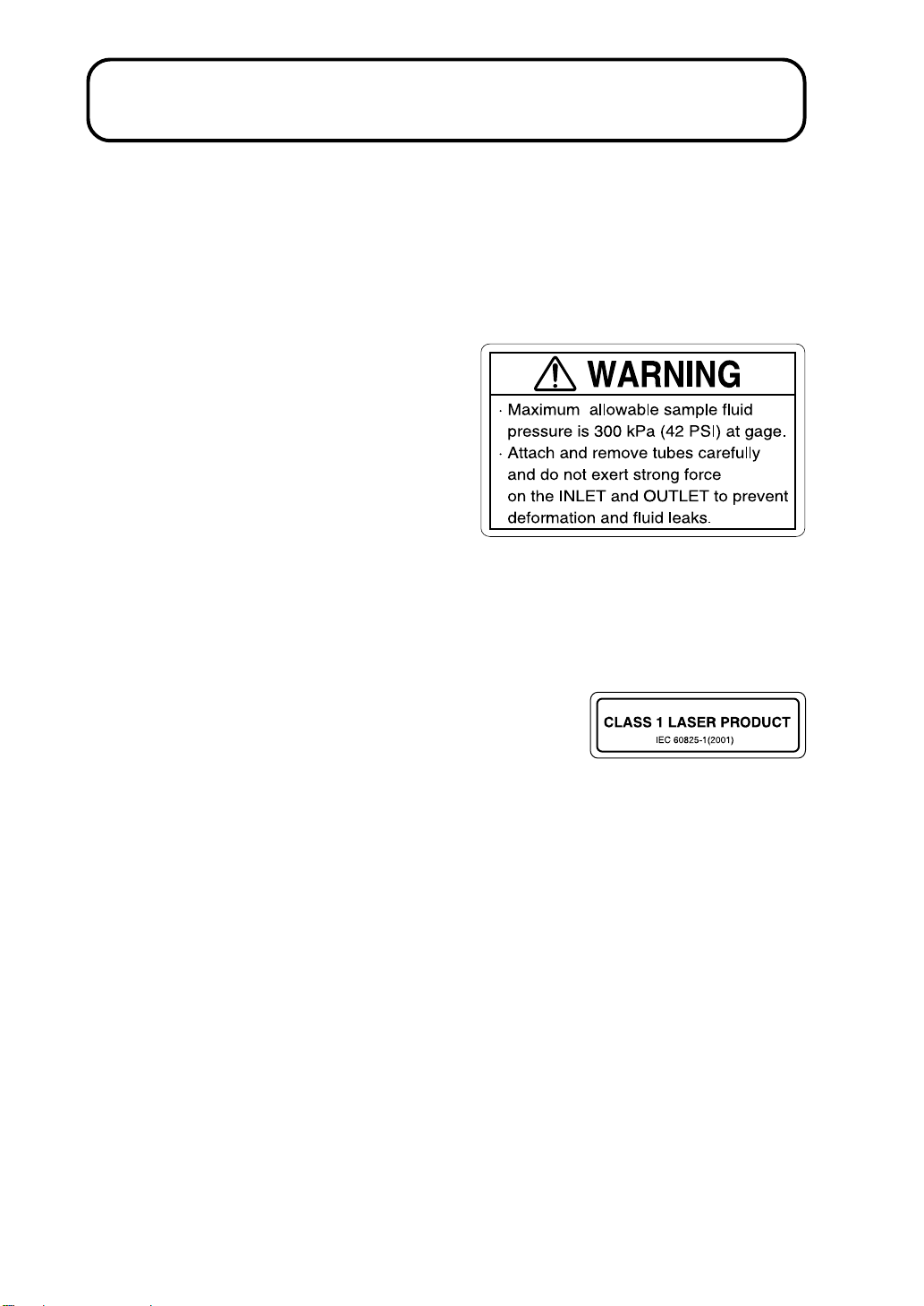
zThe pressure of sample fluid passed through the unit may not exceed
300 kPa (gauge pressure). Ensure that the supply system (sampler,
sample fluid lines etc.) has sufficient pressure resistance.
zWhen using sample fluid which may produce harmful gases, provide
adequate ventilation as prescribed by applicable laws and regulations.

v
zBefore and after measurement, clean the entire sample fluid system
thoroughly to remove any remnants. Otherwise unwanted effects such as
thermal build-up, hardening, particle accumulation etc. can occur. This is
especially important to prevent the possibility of serious accidents when
using the unit to measure different types of sample fluids.
zBefore starting to prepare the system for storage, complete the cleaning
process with pure water and verify neutrality (pH7).
zDispose of waste sample fluid only as prescribed by applicable laws and
regulations.
zNever mix waste sample fluid with other substances unless absolute safety
has been established.

vi

vii
WARNING
The unit uses a laser source
This unit is designated as a class 1 laser product
according to IEC 60825-1 (2001). The internal
particle detector mechanism uses a laser, but it is
fully shielded so that the beam cannot exit from
the enclosure.
The identification label shown at right is affixed to the top of the unit.
Laser Precautions
The particle detector mechanism in
this unit uses a laser classified as a
class 3B laser product according to
IEC 60825-1 (2001).
The laser source can cause blindness
if viewed directly, and can cause skin
injuries if the skin is exposed directly
to the beam.
Never open the cover, because this involves the risk of exposure to the laser
beam.
The warning label shown at right is affixed to the top of the unit.
Caution
Use of controls or adjustments or performance of procedures other than those
specified herein may result in hazardous radiation exposure.

viii
Warning Labels
The following types of warning labels are used with this unit.
Warning label for sample fluid and handling INLET and
OUTLET
The label specifies the maximum
sample fluid pressure as 300 kPa
(gauge pressure). The label is affixed
to the front panel of the unit. The
label also states that a shock and/or
an excessive force on the INLET and
OUTLET may cause the deformation
and/or fluid leaks.
Laser product description label (Class 1)
Indicates that this unit is designated as a class 1
laser product according to IEC 60825-1 (2001).
The label is affixed to the top of the unit.

ix
Laser product warning label (Class 3B)
Indicates that the unit internally uses
a laser classified as a class 3B laser
product according to IEC 60825-1
(2001). The laser source can cause
blindness if viewed directly, and can
cause skin injuries if the skin is
exposed directly to the beam.
The label is affixed to the top of the unit.
Cleaning label
Gives instructions for cleaning the
unit with pure water and filling it
with alcohol (isopropyl alcohol,
ethyl alcohol, methyl alcohol)
before returning it for servicing.
The label is affixed to the top of
the unit.

x

xi
Precautions
zOperate the unit only as described in this manual.
zDo not touch any parts of the unit other than necessary for operation.
zBefore using the unit, make sure that all cable and PFA tube connections
are correctly and safely established.
zIn case of malfunction, do not attempt any repairs. Note the condition of
the unit clearly and contact the supplier.
zThe end plugs are required to seal the unit when returning it for maintenance
or servicing. Store the plugs in a safe location for later use.
zBefore returning the unit for maintenance or servicing, thoroughly purge
the piping with pure water. Then fill the piping with isopropyl alcohol or
equivalent and install the end plugs.
zDo not use or store the unit in locations which
- may exceed the temperature range specified on page 48 or may be
subject to moisture condensation (If the temperature of the sample fluid
is lower than the ambient temperature, condensation may occur. Take
suitable countermeasures such as using purge gas.)
- may be subject to splashes of water or to direct sunlight, or
- may be subject to air with high salt or sulphur content or to gases, or
- which do not provide correct power supply conditions (90 to 250 V AC,
50/60 Hz), or
- which do not provide a suitable means for grounding the unit, or
- may be subject vibrations or shock.
zDo not store the unit in locations where the temperature may exceed +50°C
or drop below -10°C, where relative humidity may exceed 85%, or where
condensation or freezing inside the piping may occur.
zAvoid sudden temperature changes which may cause moisture condensation
on the optical assembly.
zDo not disassemble the unit or attempt internal alterations.

xii
Contents
FOR SAFETY ................................................................................... iii
Outline ................................................................................................ 1
Types of sample fluids .................................................................. 1
Laser source service life ............................................................... 2
Transport ....................................................................................... 2
Particle size detection ................................................................... 3
Block diagram............................................................................... 3
Measurement system configuration example ............................... 4
Controls and Features ......................................................................... 5
Main unit front panel .................................................................... 5
Main unit rear panel ...................................................................... 6
Power supply unit front panel ....................................................... 8
Power supply unit rear panel ........................................................ 9
Preparations ...................................................................................... 10
Power supply unit and power source connection........................ 10
Connecting the sampling tubes ................................................... 11
Removing the sampling tubes..................................................... 12
Purge gas ..................................................................................... 14
Before supplying the sample fluid .............................................. 15
Transfer rate/node address setting .............................................. 16
Turning the system on ................................................................ 17
Initial condition .......................................................................... 17
Measurement .................................................................................... 18
Sample fluid flow rate adjustment .............................................. 18
Measurement procedure ............................................................. 18

xiii
Maintenance ..................................................................................... 20
Steps after use ............................................................................. 20
Cleaning the piping..................................................................... 20
When the fuse has blown ............................................................ 22
Serial Interface ................................................................................. 23
Transfer principle ........................................................................ 23
Serial connector .......................................................................... 24
Interface cables ........................................................................... 24
Message format........................................................................... 26
Command messages ................................................................... 29
Information request messages .................................................... 35
Information messages ................................................................. 36
Response message ...................................................................... 44
Multi-point Monitoring System ....................................................... 45
Specifications ................................................................................... 46

xiv

1
Outline
The KS-16F is designed to be used as an in-line sensor in a system for measuring
the size and number of particles in liquid, using the light-scattering method.
Measurement results are output via a built-in interface. The KS-16F consists
of the sensor unit and the power supply unit. Particles are measured in five
size ranges (≥0.1 µm, ≥0.15 µm, ≥0.2 µm, ≥0.3 µm, ≥0.5 µm), and the sample
flow rate is 10 mL per minute.
The KS-16F does not have measurement controls or a display for measurement
results. It is designed to be used under control of external equipment such as a
computer, and to send measurement results to the external equipment A standard
serial interface and a special Rion multi-point interface for multi-point
measurements are built in.
As the KS-16F does not incorporate a flow control circuit for the sample fluid,
the flow rate of the sample fluid must be controlled by external means.
Types of sample fluids
This unit is designed to detect the size and number of particles floating in
liquid. Never use the unit with the liquid types listed below, to prevent the
possibility of accidents and damage to the unit.
- Explosive liquid or mixtures containing explosive liquid
- Liquid which can cause corrosion of fluid-contacting parts or mixtures
containing such liquid
- Liquid with a temperature of less than +15°C or more than +35°C
- Liquid with a pressure of more than 300 kPa (gauge pressure)
- Liquid which may have effects such as thermal build-up, hardening,
and particle accumulation. Always clean the system thoroughly before
using a different liquid.

2
Outline
Laser source service life
The life expectancy of a laser diode such as used in the KS-16F is shorter than
that of other semiconductors. When the laser diode nears the end of its service
life, the light output falls below the rated level. There are considerable
differences in service life between individual diodes. Some may fail already
after several thousand operation hours. The KS-16F detects when the laser
diode no longer provides the required output. In such a case, the LD indicator
flashes in red, which indicates that the laser diode must be replaced.
Transport
Before returning the unit for
maintenance or servicing, purge the
sample fluid system thoroughly
with pure water to remove any
sample fluid remnants. Then fill
the piping with alcohol (or ethyl
alcohol) and seal it with the end
plugs. Wipe the outside of the unit
clean so that there are no remnants of chemical substances on the unit.
The label shown at right is affixed to the top of the unit.

3
Outline
Particle size detection
The unit is calibrated at the factory, using particles of known diameter and
refractive index (single polystyrene latex spheres with a refractive index of
1.6) in pure water. As the amount of scattered light by such particles is used as
reference to determine the particle size, the measured size corresponds to the
light-scattering size of polystyrene latex particles.
Block diagram

4
Outline
Measurement system configuration example
With the KS-16F, measurement control and processing of measurement results
are entirely performed by a computer. A basic measurement configuration using
the serial interface is shown below. Configure your actual system according to
the measurement requirements and types of sample fluid.
For details on how to perform measurement control and how to read measurement
results etc., please refer to the section "Serial Interface" on page 23.
It is also possible to configure a multi-point monitoring system using the Rion
multi-point interface. For details, please refer to the section "Multi-point
Monitoring System" on page 45.
Important
Do not use the serial interface and the multi-
point interface at the same time. Correct opera-
tion of the unit is not assured if control is at-
tempted via both interfaces.
The service life of the light source (laser diode)
is limited. While no measurement is being car-
ried out, the light source should be turned off as
much as possible.
Table of contents
Other Rion Accessories manuals