Riptide Nautilus 5.8 User manual

Riptide Nautilus 5.8
IN-GROUND EXERCISE POOLS
OWNER’S MANUAL

CONTENTS
2
RIPTIDE NAUTILUS 5.8 TURBO 3
IMPORTANT SAFETY INFORMATION 4
INSTALLATION AND SET-UP
Selecting a site for your pool 5
Electrical requirements and connections 5
Checklist before filling your pool 6
JET CONFIGURATIONS 6
IN-GROUND INSTALLATION 7
DIAGRAMS 10
CONTROL PANEL OPERATIONS
Control system features 12
Main control panel 13
Notification icons 13
Spa functions 13
Spa mode 14
Settings 14
Water care 15
Modifying water care schedules 15
Maintenance 16
Date and time 16
Keypad settings 17
Miscellaneous 17
About your spa system 18
Wifi 18
Electrical configuration 18
Audio mode 19
On/off 19
Speakers setting 19
Audio source selector 19
Disconnect Bluetooth 19
Variable speed drive control panel 20
OTHER FUNCTIONS 20
Freeze protection 20
Clean cycle 20
Circulation pump 20
Ozone generator 20
TROUBLESHOOTING GUIDE
Diagnostics - IN.K 1000 error codes 21
Diagnostics - operation 22
MAINTENANCE
Water chemistry 23
Overview of water chemistry 23
Starting your pool with new water 24
Maintaining pool water 24
Water chemistry troubleshooting 24
Riptide total alkalinity (TA) adjustment chart 25
Changing your pool water 26
Drain operation 26
Cleaning your filters 26
Pool shell care 26
Cleaning and protecting the headrests 26
Cover care 26
Miscellaneous care 27
Low-use or no-use periods 27
Pool winterization 27
Pool de-winterization 27

RipTidE NauTiluS 5.8 TuRBO IN-GROUND
3
RIPTIDE NAUTILUS 5.8 TURBO
RIPTIDE NAUTILUS 5.8 TURBO PRO

When installing and using this electrical equipment, basic
safety precautions should always be followed, including the
following:
1. READ AND FOLLOW ALL INSTRUCTIONS.
2. WARNING - To reduce the risk of injury, do not
permit children to use this product unless they
are closely supervised at all times.
3. In standard form, the Riptide pool requires only one
supply of 240 volts 32 amp or 45 amp. Please consult with
a qualified electrician to verify current legislation
ALWAYS USE A QUALIFIED ELECTRICIAN TO
CONNECT THIS POOL TO YOUR ELECTRICITY
SUPPLY
4. DANGER - risk of accidental drowning. Extreme
caution must be exercised to prevent unauthorised access
by children. To avoid accidents, ensure that children cannot
use the Riptide pool unless they are supervised at all times.
5. DANGER - risk of injury. The suction fittings in
the Riptide pool are sized to match the specific water flow
created by the pump. Should the need arise to replace the
suction fittings or the pump, be sure that the flow rates are
compatible. Never operate the Riptide pool if the suction
fittings are broken or missing. Never replace a suction fitting
with one rated lower than the flow rate marked on the original
suction fitting.
6. DANGER - risk of electric shock. Do not permit
any electrical appliance, such as a light, telephone, radio,
or television, within 5 feet (1.5m) of the unit. These units
have an integral ground fault circuit interrupter, but this only
covers the pools’ own electrics.
7. WARNING - to reduce the risk of injury:
a) Before entering the pool check the temperature.
b) Since excessive water temperatures have a high potential
for causing foetal damage during the early months of
pregnancy, pregnant or possibly pregnant women should
seek advice before using a pool and should maintain safe
water temperatures.
c) The counter-current of the Riptide pool is extremely
powerful and could cause injury if used incorrectly. Do not
stand next to the counter-current nozzles when the motor is
running. Ideally, you should be placed at least 1 meter from
the nozzles. Never attempt to adjust the swim jet nozzles
whilst the motor is running
d) The use of alcohol, drugs, or medication, before or during
pool use, may lead to unconsciousness with the possibility
of drowning.
e) Persons suffering from obesity, or with a medical history of
heart disease, low or high blood pressure, circulatory system
problems, or diabetes, should consult a physician before
using a Riptide pool.
f) Persons using medication should consult a physician
before using the pool since some medication may induce
drowsiness while other medication may affect heart rate,
blood pressure and circulation.
ADDITIONAL SAFETY INSTRUCTIONS:
1. WARNING - risk of fatal hypothermia.
a) The use of alcohol, drugs, or medication can greatly
increase the risk of fatal Hypothermia in a pool.
b) The causes, symptoms, and effects of Hypothermia may be
described as follows: Hypothermia occurs when the internal
temperature of the body reaches a level several degrees
below the normal body temperature of 37°C (98.6°F). The
symptoms of Hypothermia include an decrease in the internal
temperature of the body, dizziness, lethargy, drowsiness, and
fainting. The effects of Hypothermia include:
• Unawareness of impending hazard;
• Failure to perceive cold;
• Failure to recognize the need to exit the pool;
• Physical inability to exit the pool;
• Foetal damage in pregnant women; and
• Unconsciousness and danger of drowning.
2. WARNING - risk to infants, the elderly, and
women planning pregnancy or during pregnancy.
Please consult your physician if the above applies to you or
anyone using your pool.
3. WARNING - risk of children drowning. Although
your Riptide pool cover is not rated as a safety cover, it is
wise to always keep the pool cover securely fastened when
not in use. This will help discourage children from attempting
to enter the pool when not supervised by an adult.
4. WARNING - risk of drowning. Use caution when
bathing alone. Overexposure to hot water may
cause nausea, dizziness, and fainting.
5. WARNING - risk of injury. Always use extreme
caution while entering or exiting the pool. Surfaces can be
very slippery when wet. Do not step or sit on head rests.
Keep all breakable objects out of the pool area.
6. WARNING - risk of injury. Never use the pool
immediately after strenuous exercise.
7. WARNING - risk of injury. Individuals with infectious
diseases should not use the pool
8. WARNING - risk of injury. Maintain water chemistry
in accordance with chemical manufacturer’s instructions.
9. WARNING - risk of shock. The pool must not be
operated in severe weather conditions, i.e. electrical storms.
10. CAUTION - unauthorised access. Secure
the pool area against unauthorised access. Make sure all
barriers meet local codes. Keep the pool cover on pool when
not being used.
11. CAUTION - risk of damage to pool or
equipment. By performing maintenance as described
later in this Owner’s Manual, the chance of damage to your
pool and its equipment will be greatly reduced. Never block
the air vents that lead to the equipment compartment. Doing
so may cause the pool equipment to overheat.
12. CAUTION - non-approved accessories. Using
accessories not approved by the manufacturer could void
your guarantee or cause other problems. Please consult with
your authorised Riptide dealer.
13. CAUTION - location of your Riptide pool.
Locate your Riptide pool on a surface that can withstand
the weight bearing requirements of the pool (see Selecting
a Site for your Riptide pool in this Manual). Also, locate your
pool in an environment that can withstand repeated exposure
to water and the possibility of a major spill.
iMpORTaNT SaFETY iNFORMaTiON
4

4
SELECTING A SITE FOR YOUR RIPTIDE
POOL
Your Riptide pool is designed for either indoor or
outdoor use. In either case, please adhere to the
following guidelines:
1. Select a site that is stable and capable of supporting
the weight of your pool, its water, and the people
using it (refer to the model brochure or contact an
authorised Riptide dealer for the filled weight of
your pool). If installed on a suspended floor/deck, it
should be capable of supporting your pool. If you have
concerns on this matter, please contact a qualified,
licensed contractor.
2. The surface needs to be flat and level as it must
provide continuous support for the entire bottom of
the pool structure. Do not shim or block up the pool
creating voids below the base framework. If you do not
intend to use a pit please ensure you have adequate
drainage or a soak away.
Indoor considerations: There are several
considerations when installing your Riptide pool
indoors: the environment both around and below the
pool should be water resistant. It must be capable of
handling water splashed out from the pool as well as
the possibility of a leak from the vessel (a catch basin
equivalent to the volume of your pool is recommended);
it is recommended that the room you install the pool
in has proper ventilation. This can usually be achieved
by an exhaust fan or a dehumidifier if pool is used for
less than one hour per day.
Note: Typical indoor surfaces include, but are not
limited to: concrete; wood; non-slip tile or linoleum.
Outdoor Considerations: When selecting an
outdoor site, several things should be considered.
Firstly, avoid selecting a site where excessive water
may contact the pool such as from sprinklers or a
roof edge without rain gutters. If possible, avoid areas
of direct, prolonged sunlight. The ultraviolet rays of
sunlight will tend to fade and damage your Riptide
pool cover. Lastly, avoid locating your pool in an area
where debris could be blown into the pool.
ELECTRICAL REQUIREMENTS
and CONNECTIONS
All Riptide pools must be wired in accordance with
all national electric codes. Always use a qualified
electrician to perform the electrical installation.
WIRING DIAGRAMS
Please reference the wiring diagram specific to your
Riptide pool‘s control system:
• Standard Riptide pool 32 amp / 45 amp model
control system
— one input 240V 32 amp / 45 amp single phase
220/240 VOLT INSTALLATION
Use only a qualified, licensed electrician to make 240
Volt electrical installations.
Your 220/240 Volt standard Riptide pool 32 amp
/ 45 amp model requires one fused and dedicated
electrical circuit of 32 amp / 45 amp and a minimum
supply wire size of 6mm. It is important that these
circuits are dedicated (not being used by any other
electrical appliance) or your pool may not function
properly.
The 220/240V Riptide pool 45 amp model requires
one fused and dedicated electrical circuit of 45 amp
and a minimum supply wire size of 6mm. It is important
that these circuits are dedicated (not being used by
any other electrical appliance) or your pool may not
function properly.
Position your Riptide pool at least 150cm [5ft] from all
electrical outlets or devices.
ELECTRICIAN’S INSTRUCTIONS
We strongly recommend that a suitable seal cable
guide is installed to retain the water tight seal of
the control boxes. The incoming power line must
be suitably fused and protected to a C.E. minimum
standard and any national specific regulations
required.
iNSTallaTiON & SET-up
5

CHECKLIST BEFORE FILLING YOUR POOL
Important: The equipment should never be operated
without water in the pool. Serious damage to the
equipment will occur.
1. Installing your cover: Your Riptide pool cover
comes with tie-down straps and locking hardware to
attach the cover to the pool cabinet or decking.
2. Check drain valves: Check that the pool drain
valve is fully closed.
3. Tighten equipment fittings: In the equipment
compartment, hand-tighten all PVC pipe unions,
pump bleed valve and pump drain plugs to prevent
the possibility of leakage (sometimes these fittings
loosen during shipment). Check also that all fittings
on the filter are closed (HAND TIGHT ONLY! ).
4. Check Valve: Verify that all valves aside from the
drainage valves described previously are in the fully
open position. A valve that is half closed will result in
a noisy pump due to lack of water flow.
5. Fill the pool: Fill the pool to approximately the
halfway point on the skimmers.
iNSTallaTiON & SET-up
JET CONFiGuRaTiONS
6. Water overflow Built into the back of the skimmer
on all models except Oceana, is a water overflow. The
overflow stops rain water from over filling the pool.
Excess water will flow out from the corner adjacent to
the overflow.
Note 1: The higher the water level, the less pool users
it will take to cause the water to overflow the pool
edge. Also, water will splash out more easily whilst
swimming in the pool if it is over-filled.
Note 2:
If you live in a hard water area and have access to
softened water please add 20% hard to 80% soft to
achieve 250-500 parts per million.
6. Check for leaks: After the Riptide pool is full, but
before turning the power on, check all the fittings and
equipment in the equipment compartment for signs of
leakage. If a leak is detected, except from fittings that
can be hand-tightened, call your authorised Riptide
dealer.
6
4 JET TURBO MODEL
Option 1
The 4 Turbo jets are powered by 3 x 3.5hp pumps via
wide 3” plumbing, providing more water to each jet.
The controls allow the operation of the top 2 jets, the
bottom 2 jets or all 4 jets at once.
Option 2
The 4 Turbo jets are powered by 3 x 3.5hp pumps via
3” plumbing. The top 2 turbo jets are run via a 10 level
variable speed drive to give more control of the water
current which can be adjusted to suit the swimmer.
The bottom 2 jets can be used on their own for a gentle
swim or in conjunction with the top 2 jets to provide a
very strong, adjustable swim current.
7
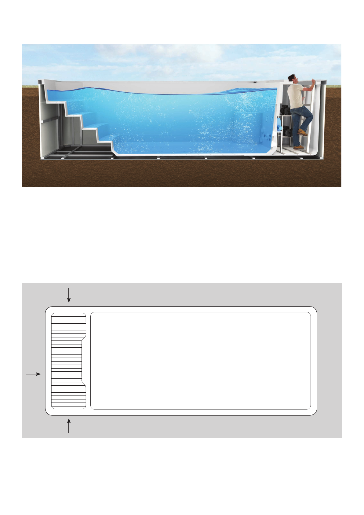
iN-GROuNd iNSTallaTiON
Once installed, pool maintenance including adding
chemicals and filter cleaning and replacement can be
carried out by the pool side. All the pool components
can be accessed via the service hatch.
Unless something stops functioning you can carry
out maintenance from the pool side, but in the event
of a breakdown an engineer can simply lift off the
waterproof end cover and drop down through the
service hatch to repair or replace as needed.
The only consideration here is that your electrician
will need to supply a suitable cable with a waterproof
gland to pass through the fiberglass wall into the
service area.
The best option is for the install team to drill the hole
as high as possible at the time of installation and feed
the power cable through via the waterproof gland and
then directly into the control box. In some countries
only certified electricians can make the final electrical
connection so please check with your dealer.
Electrical power supply
access point options
Pit: 7m x 3.3m

8
iN-GROuNd iNSTallaTiON
To sink or semi sink the Nautilus pool you will
first need to dig out a pit approximately 7m
long by 3.3m wide.
Please note that the crane stropes will need
to be removed once the pool is in the pit so
bear in mind that a worker needs to be able
to stand in the hole with the pool to pull the
strops out. If this means the pit needs to be
a little larger, please adjust the pit size as
required.
The depth of the pit will depend on the required
finished height of the pool. The height from the
pool base to the underside of the pool lip is
1425mm + or - 30mm.
The bottom of your pit will also need a flat,
level 6” reinforced concrete base, so an
extra amount of soil should be removed to
allow for this.
Requirements for correct site selection
should include checking the ground water
level as this should be lower than the pool
base. Ensure that the ground around the
pool is drainable; if not then large soakaways
should be constructed to ensure the pool
will not flood.
To avoid the pool floating if any underground
water is present, the glavanised steel pool
frame should be bolted to the 6” reinforced
concrete base at the eight points indicated.
On delivery day the pool will be lowered
into your prepared pit with a crane or hiab.
It is not possible to man-handle this product
so thought must be given to access for the
crane or hiab.
Ensure the pool is located with the steps end
in the preferred direction. Once determined,
the pool will be lowered down into your pit
and centred as you require. It is normal to
use some small wood sections under the
pool to allow for the strops to be removed. A
delivery technician will get in the pit and with
the help of the crane, lift each end one at a
time to remove the wood sections. Access
space of around 500mm around all four
sides of the pool is required for this purpose.
Fixing points
to galvanised
steel pool frame
9
iN-GROuNd iNSTallaTiON
Once the pool is in the correct position
fill with water to let it settle down to its
true height.
Now is the time to drill the hole for the
power cable in the technical end of the
pool and fit with a waterproof gland.
Next, fix 50-60mm waterproof insulation
boards to the outside of the pool’s
fiberglass hull with a product like Gripfill or
equivalent. Then backfill the gap between
the pool and the ground with small gravel
to aid the drainage of excess water away
from the pool sides.
Top off the gravel with top soil, paving
slabs, decking or tiles as required.
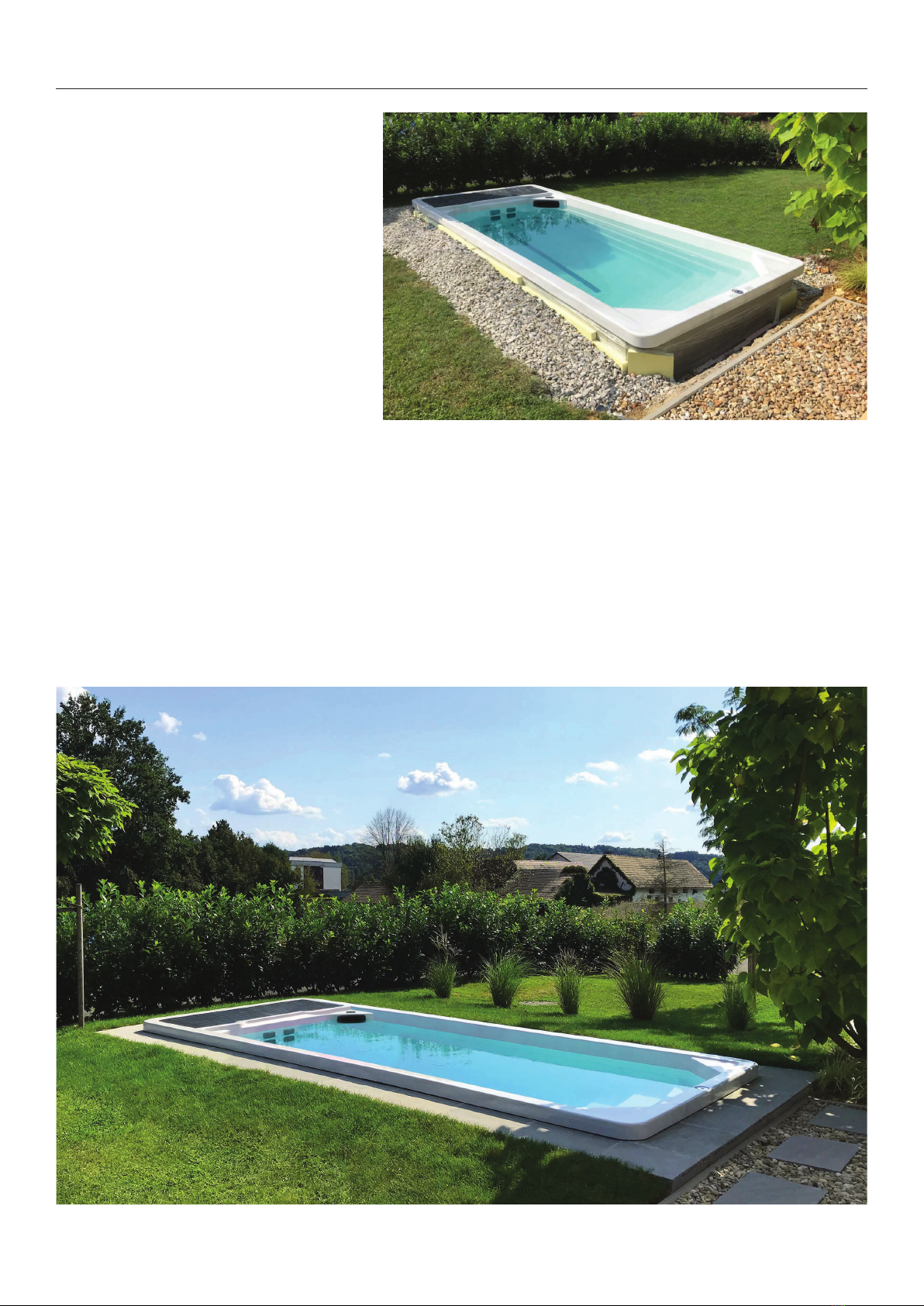
Covers
Covers are essential for keeping your pool both clean
and the water hot. You can sink your pool up to the
lip like the pool installation in the photo below but you
can limit your cover options.
On a pool installation like this only hard covers will
operate correctly, with the plastic side straps fitted to
the surface around your pool. Care will then need to
be taken not to stand on the plastic catches as they
may break.
If you require a roll up cover or hard covers with a
cover lift system fitted then it is best to have the pool
semi sunk into the ground to allow for the strap fixings
to be fastened onto the sides of the pool. Allow about
300mm height above the ground for this option.

diaGRaMS
10
RIPTIDE NAUTILUS 5.8 TURBO
1. 3HP Single Speed Pump
2. Control Box
3. Ozone Clear Core Chamber
4. Ozone Generator
5. Circulation Pump
6. Control Panel

1. 2” Jet Internal-Directional
2. 3” Jet Internal-Directional
3. 3” Jet Two Speed
4. 4” Jet Single Speed
5. 1” Air Check Valve Assembly
6. Two Cylinder Skimmer
7. 2” Suction
8. Ozone Injector
9. Swim Jet
10. 5” Light Housing
11. 2” Infinity LED
12. Large Face Direct Jet Insert
13. Stainless Steel Handrail
14. Stainless Steel Swim Base
Section A Section B
diaGRaMS
11
RIPTIDE NAUTILUS 5.8 TURBO
CONTROl paNEl OpERaTiONS
CONTROL SYSTEM FEATURES
The fully programmable control system on Riptide
pools allows total management of the water
temperature and jet power at the touch of a button.
Also included is an automatic timer switch and
operational safety features to ensure a safe and relaxing
pool experience.
Heater control
You can set the water temperature to suit the activity:
hot for just relaxing, cooler for exercise. You can also
set the water temperature in advance ensuring your
pool is ready for use anytime you wish.
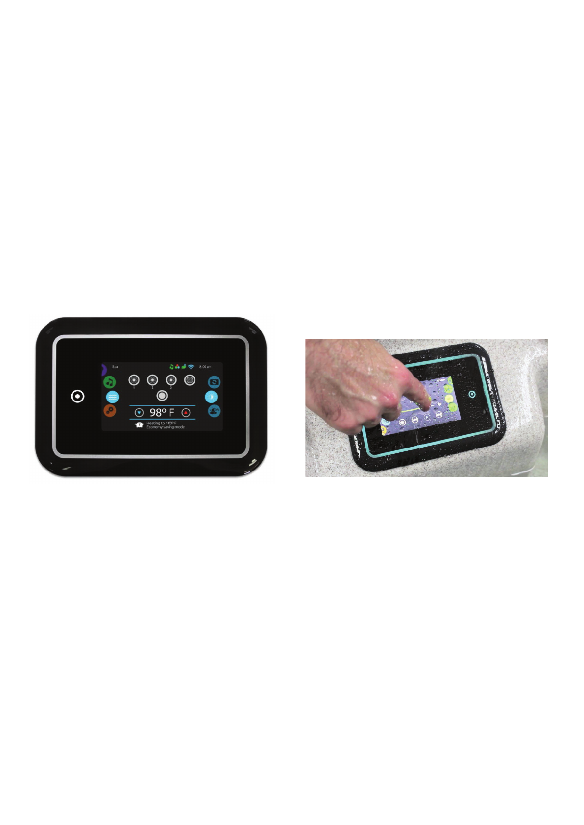
The Gecko in.k1000 capacitive touch screen display
keypad fitted to the Nautilus range will operate under
wet and rainy conditions.
Jet control
The speed of the jets is fully adjustable via the simple
to operate buttons on the control panel.
Audio system (optional)
The integrated audio system features 4 transducer
speakers and a sub woofer speaker.
Safety features
The control system has multiple safety features including
water flow protection, high and low voltage protection,
high and low temperature protection and anti dry heating
protection to guarantee the pool operates safely.
The control box is fully waterproof with International
Protection Rating (IP) 55.
Keypad - Nautilus 5.8 Turbo Models
12
13
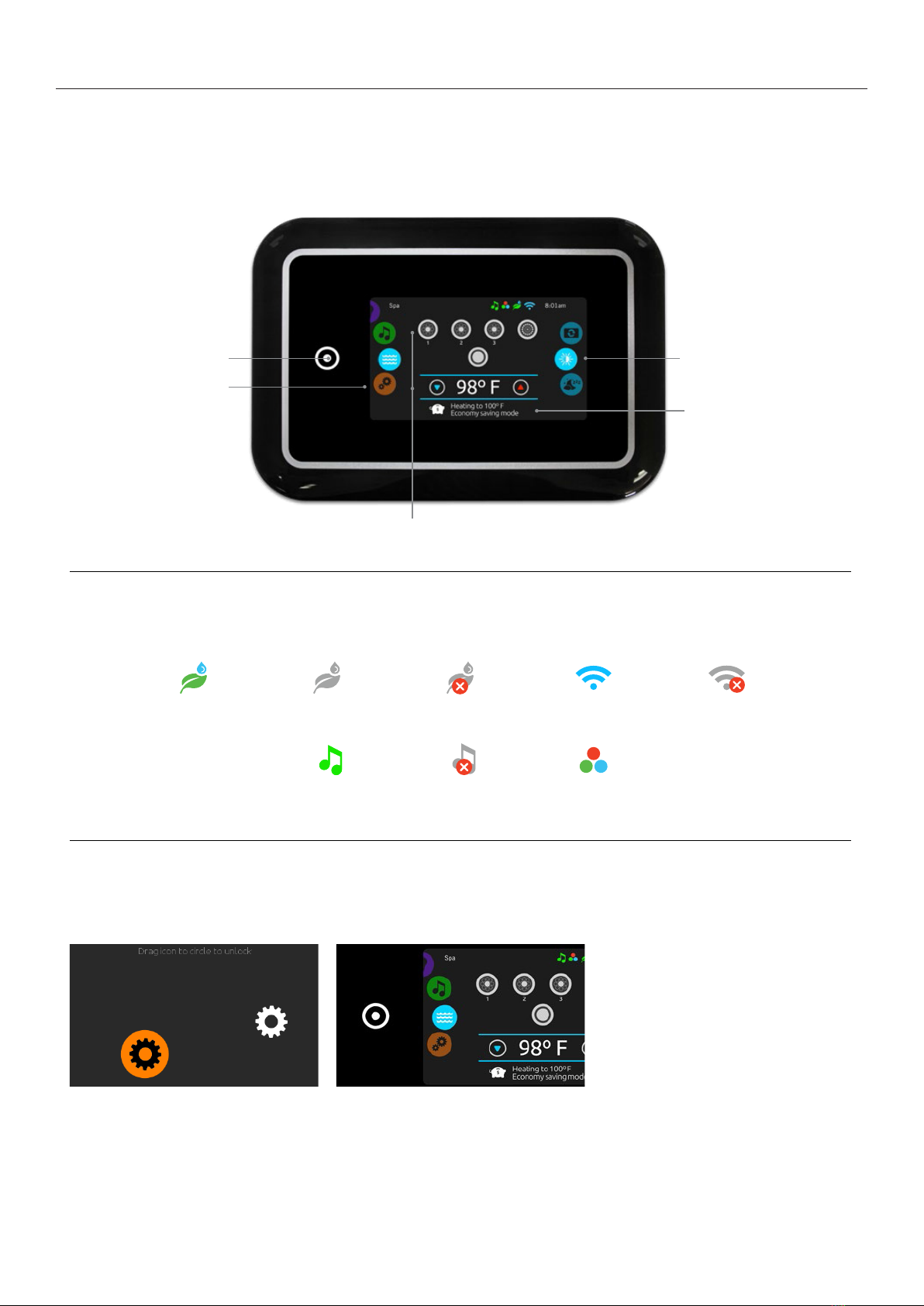
MAIN CoNtrol PANel in.k 1000 Touch Screen Keypad
CONTROl paNEl OpERaTiONS
1
Quick ReferenceCard
Please consultyour spa user manual for complete info on the features of yourspa system.
in.k1000
touch screen keypad
No buttons, keys and overlays! Mode and functionselection wheels, all-on or all-offone touchactivation keyof last
used settings, interactive display icons and on-screen messages are all elements of the in.k1000 user interface
designed to let spa users interact intuitively with theirspa and its value-added accessories.
notification icons
Notification icons at the top right-hand side of the screen show the status of connected value-added accessories.
spas functions
Quick and easy step-by-step instructions to control the main functions and
to configure systemsettings of your spa from its in.k1000 main spa keypad.
in.clear
system is on
in.clear
system is idle
in.clear
system is off
in.stream 2 audio
system is on
in.stream 2 audio
system is off
in.mix
is installed
system is connected
to wifi
system is not
connected to wifi
All-on or all-off key
(one touch activation)
direct to function
selection wheel
(settings and
additional options)
on-screen
system message
and reminder
interactive display icons
(main spa functions)
mode selection
wheel (settings
andaccessories)
turn keypad on
3 minutes after the last pump is turned off, the
screen will shut off ifthere is no touch activity.
Touch the screen toturn on the keypad.
Then follow the instructions on the screen to
access the main screen.
all-on, all-offtarget key
in.k1000 featuresan all-on or all-off one touch
activation key. When pressed, it tops or starts all
working components and accessories at once.
From the home page, you can access the
following modes:
•sanitization (with in.clear connected)
•audio (with in.stream 2 connected)
•color (with in.mix installed)
•spa
•settings
To select a mode, slide the left wheel up ordown
until the desired icon menu is highlighted in the
middle.
Blow-
er
14
CONTROl paNEl OpERaTiONS
1
direct to function
selection wheel:
water care -
maintenance -
date & time -
keypad -
electrical config -
wifi -
about -
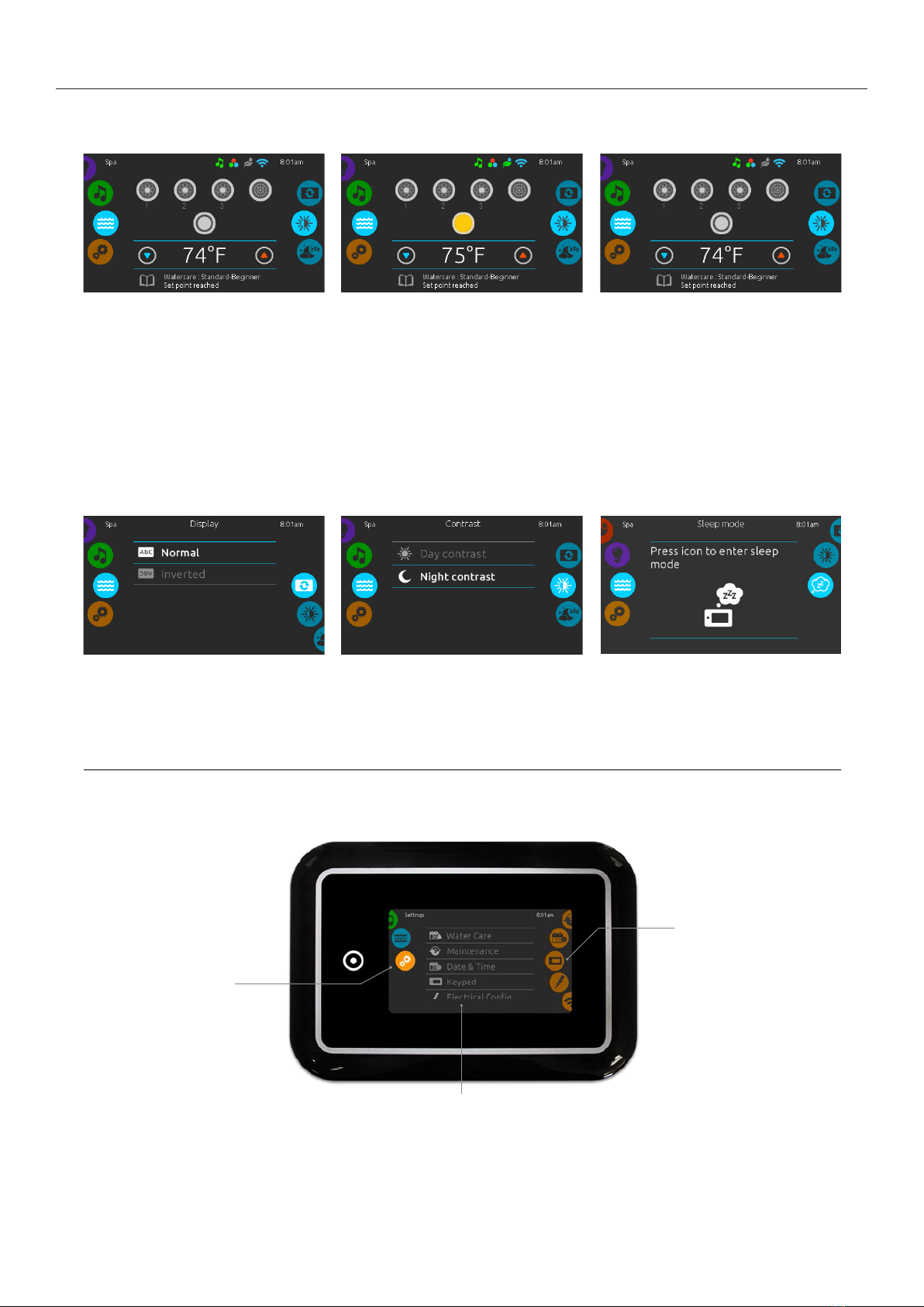
spa mode
spa mode
To select the spa mode,slide the left wheel up
or down until the spa icon is highlighted in the
middle.
The home page will display its equipment
start or stop keys, up and down buttons, water
temperature, messages and quick access to
display options:
• display orientation
• display contrast
To select an option, slide the right wheel up or
down until the desire icon menu is highlighted in
the middle.
display orientation
To modify the display orientation settings, slide
the right wheel until the display orientation icon is
highlighted in the middle.
Simply touch the line of the orientation you want
to select.
start orstop accessories
To startorstop an accessory (pump, blower,
light), touch theassociated icon. Icons will
become animated when their accessory is turn
on,and animation will stop when turn off.
Icons onthe screen will reflect the speed or state
of the devices running on your spa. When an
accessory has more than one speeds press the
button until it reaches the desired speed.
display contrast
To modify the display contrast settings, slide
theright wheel until the display contrasticon is
highlightedin the middle.
Simply touch the line of the contrast you want
to select.
water temperature
The temperatureat the bottom of the screen
shows the current water temperature. Use the Up
and Down icon to set the desired temperature.
The set point will appear in blue. After 3 seconds
without any changes to the set temperature value,
the current watertemperature will reappear.
When the set value is lower than the current
temperature Cooling to xx.x will appearbelow.
When the set value is higher than the current
temperature, Heating to xx.x will be indicated
under the value. Normally there is a short delay
before the heating starts,during which Heating
Suspended is indicated under the value.
list of featured items
mode selection
wheel:
settings icon
settings
Youcan usethe Settings mode to manage settings of your spa system.
To select the settings mode, slide theleft wheel up or down until the settings icon menu is highlighted in
themiddle.
In the Settings page you can access the following:
• water care • electricalconfiguration
• maintenance • wifi
• date & time • miscellaneous
• keypad • about
To select anitem, slide the right wheel until the desired icon is highlighted inthe middle or press on the
menu name.
sleep
Press key togodirectly into the sleep mode. In
sleep mode, water splashing on the keypad can't
inadvertently start/stop a pump.

CONTROl paNEl OpERaTiONS
1
water care
TheWater care page will help you set up your ideal filtration and heating settings.The Water care page
will help youset up your ideal filtration and heating settings. Choose, set or modify one of the
5 suggested modes depending on your needs at any given time.
Away from home
In this mode the
spa will always be in
economy; the set point
will be reduced
by 20° F.
Beginner
Thespawill never be
in economy mode
andwill be filtering
according to the pack's
low level configuration.
Energy Savings
The spa will be in
economy modeduring
the peak hours of
the day and resume
normal mode on
the weekend.
Super Energy
The spa will always
be in economy mode
during peak hours,
every day of the week.
Weekender
The spa will bein
economy modefrom
Monday to Friday, and
will run normally on
the weekend.
modifying water care schedules
water care
To modify a Water care category, touch the pen
icon at the right end of the desired water care to
open the selected Water Care menu.
In Economy mode, the set point will be reduced
by 20°F, which means that the heating system
will not be engaged unless the temperature falls to
20°F below the spa's set temperature.
The filtration schedule show on the screen will be
applied to the main filtration pump, mostlikely
pump 1. If your spa uses a circulation pump
configured to run 24 hours, the screen will show
you the purge setting instead of filtration.
The purges are pre-programmed for a fix number
of minutes, therefore the duration will be set to
N/A on the screen, and only the start time can be
modified.
economy
Touch the Economy tab to change the economy
schedule. You can add economy schedules by
touchingthe « + » symbol .
To delete aschedule, touch the garbage can icon
at the right end of the desired line.
Youcan modify the programmed schedules by
selecting one and adjusting the schedule.
Youhaveseveral possibilities for the schedule
(Mon-Fri, weekend, every day, or single days).
Theschedules will be repeated every week.
Thetime andduration are setin 30 minute
increments.
purges
Touch the Purgetab to change the purge
settings. You can add purges by touching the
« + » symbol.
To delete aschedule, touch the garbage can icon
at the right end of the desired line.
filter cycles
Touch the Filter cycletab to change the filter
cycle schedules. You can add filtration schedules
by touching the « + »symbol .
To delete a schedule, touch the garbagecan icon
at the rightend of the desired line.
Once you have set the schedule, use thecalendar
icon to go back.
You can modify the programmed purges by
selecting one and adjusting the schedule.
You have several possibilities for the schedule
(Mon-Fri, weekend, every day, or single days).
The schedules will be repeated every week.
The time andduration are setin 30 minute
increments.Once you haveset the purge,
use the calendar icon to go back.
15
16
CONTROl paNEl OpERaTiONS
1
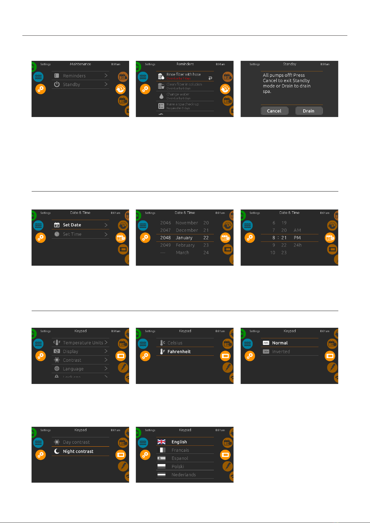
maintenance
date andtime
keypad settings
maintenance
To modify maintenance settings, slide the right
wheel until the maintenance icon is highlighted
in the middle.
From the Maintenance page you can access
the following:
• Reminders
• Standby
Simply touch the line of the item you want
to change.
date and time
To modify date and timesettings, slide the right
wheel until the date and time icon is highlighted
in the middle.
Simply touch the line of the item you want to
change.
keypad settings
To modify keypad settings, slide the right wheel
until the keypad icon is highlighted in the middle.
Simply touch the line of the item you want to
change.
display contrast
Use this page to set or change the display day or
night contrast.
reminders
Thein.k1000 keypad will provide reminders
about maintenance required on your spa, like
rinsing or cleaning the filter. Every task has its own
duration, based on normal use.
Thereminders menu allows you to check the time
left before maintenance is required, as well as to
reset the time once a taskhas been completed.
To reseta task, select itby pressing the curved
arrow, then confirmwhen prompted. Once you
have confirmed,the task will be reset.
setdate
Here you canadjust the year, month and date.
Simply swipe upand down the column you want
to change, and select the desired value. When
done, touch thecalendar icon at the right of the
screen.
temperature units
Usethis page to set or change the temperature in
F˚ or C˚ units.
display language
Usethis page to set or change the display
language.
standby
The Standby mode allows you to service your
spa. Pumps will stop for 30 minutes and will
automatically restart after this time.
Once Standbymode is activated a screen will
appear to show that pumps have stopped.
The normal spa page will return at the end of
maintenance.
When the Drain key is pressed, pump 1
low or circulation pump (depending on spa
configuration) is activated to drain the spa.
set time
Here you canchange the hour, minute and time
format.Simply swipe up and down the column
youwant to change, and select the desired value.
When done, touch the calendar icon at the right
of the screen
display orientation
Use this page to set or change the normal or
inverted display orientation.

17
CONTROl paNEl OpERaTiONS
1
keypad settings
keypad lock/unlock (optional)
When this option is enabled, the user can partially
or completely lock the keypad.
When Full Lock is selected, all functions are
locked.
In Partial Lock, you may only activate accessories.
Settings may not be changed in this mode.
keypad color (optional)
If this option is available (depending on the spa
configuration), the keypad rim color can be
changed.
8 pre-defined colors are available. If the in.mix
is installed, the keypad rim color can also be
associated to an in.mix zone.
When the user wants to lock the keypad he is
asked toselecta 4-digit code. The same code will
be needed tounlock the keypad.
Next time he wants to lock the keypad, he will be
prompted again to select a 4-digit code(same
functionality as a Safe ina hotel room).
The keypad can be unlocked with a universal
unlock code (3732) or by a reset of thekeypad.
miscellaneous
This menu gives access to modify the Warm
Weather option and info messages in the media
center.
warm weather
TheWarmweather option allows you to bypass
thepackfiltration over-temperature feature.
When Warm weather is On, the filtration over-
temperature is disabled. This feature allows the
spato continue filtering even though the water
temperature is high.
info messages
Press display/hide key to modify message display:
If hide option is selected, smart wintermode
message will only appear when a SWMpurge is in
action. Otherwise the message will always appear
when the spa is in a SWM condition.
If hide option is selected, heating suspended and
filtering suspended messages will not appear.
miscellaneous

18
CONTROl paNEl OpERaTiONS
1
wifi
(This function is available only if an in.touch module is connected to your system.)
wifi settings
To modify wifi network settings, slide the right
wheel until the wifi icon is highlighted in the
middle.
in.touch module not connected
If the in.touchmodule of your spa system is not
connected, this message will be displayed.
wifi networks
After a few seconds the available networks will
appear on-screen, as well as their signal strength.
Select network will be identified by a green check
mark.
Swipe Up or Down the list to select your network.
wifi network password
If the wifi network is password protected, enter
it when keyboard prompts. Use Enterkey to
validate thepassword.
If no password is required the in.touch will
connect automatically.
electrical configuration
Please do not make changes in this section
unless you areaqualified electrician.
about
To get info about your spa system, slide the right
wheel until theabout icon is highlighted in the
middle.
Information aboutthe in.k1000 software number
andthe revision numbers of the different
components of your system will be displayed.
about your spa system
wifi (in.touch 2)
When a in.touch 2 is detected, this network will
appear.

CONTROl paNEl OpERaTiONS
1
direct to function
selection wheel:
on/off -
speakers -
source -
bluetooth -
mute / last track / play/pause / next track
mode selection
wheel:
audio mode
audio mode
(only available if the system detects a connected in.stream 2 audiostation)
To select the audio mode, slide theleft wheel up or down until the audio icon menu is highlighted in the middle.
In the Audiopageyou can access the following:
• in.stream 2 on/off • audiosource selector
• speaker calibration • disconnect bluetooth
To select an item, slide the right wheel until the desired icon is highlighted in themiddle.
on/off
speakers setting audio source selector disconnect bluetooth
turn in.stream 2 ON (icon red)
Slide the right wheel until the power on/off icon
is highlighted in the middle. Press the icon at the
center of the screen to turn in.stream 2 on.
to modify your speaker settings
Slide the right wheel until the speaker calibration
icon is highlighted in the middle.
You can adjust:
• balance
• fade
• subwoofer
Usethe sliders to change the speaker settings at
the desired level.
The fade and subwoofer sliders will only appear
on the screen if the corresponding speakers are
installed on the in.stream 2.
turn in.stream 2 OFF (icon green)
Press the icon at the center of the screen to turn
in.stream 2 off.
to select an audio source
Slide the right wheel until the source icon is
highlightedin the middle.
In the menu list, the following sources are
available:
• Bluetooth
• FM
• USB
• Aux. 1
Simply select the desired one to use.
Note that only the sources installed on the
in.stream 2will be displayedin the source menu.
Please note that the Play/Pause and Change
Track functionsapply to devices using Bluetooth
technology and USB, and will not work when AUX
is selected as the source.
main display
Press Play / Pause to start or pause playback of
audio files.
Drag the volume slider to adjust the volume or tap
the mute buttonto mute or unmute sound.
Press the last track or next track buttons to go to
the previous song or skip to the next.
If a device with Bluetooth technology is connected
to the in.stream 2, you can disconnect it by
pressing the Disconnect key at the bottom ofthe
screen.
Doing so will also prevent the in.stream 2 from
automatically reconnecting to this specific device
until it has beenreconnected using thedevice
itself.
19

20
CONTROl paNEl OpERaTiONS
VARIABLE SPEED DRIVE
CONTROL PANEL
Fitted to the Pro model, the Variable Speed Drive
Auxiliary Control Panel operates the Variable Speed
Drive (VSD) jet speed.
The main control panel must first be turned on for the
variable speed drive to operate. Once turned on, the
current can be increased or reduced by using the up
and down buttons on the control.
FREEZE PROTECTION
If the sensors within the heater detect a very low
temperature, the pumps and blower automatically
activate to provide freeze protection. The pumps and
blower will run continuously or periodically depending
on the conditions.
CLEAN CYCLE
At the beginning of the filtration cycle, a pump will
automatically operate for 1 minute to clean the spa
water.
CIRCULATION PUMP
The circulation pump operates during filtration and
when the heater is in operation.
OZONE GENERATOR
The ozone generator will operate during filtration cycles.
OThER FuNCTiONS
21
Table of contents
Other Riptide Swimming Pool manuals


Popular Swimming Pool manuals by other brands


Endless Pools
Endless Pools FASTLANE PRO owner's manual

Piscine Laghetto
Piscine Laghetto Dolce Vita GOLD Assembly instructions

BWT
BWT 3 x 3 Installation and operating intructions

Bestway
Bestway 54370 instructions

Bestway
Bestway POWER STEEL 56622E owner's manual

Polygroup
Polygroup SUMMER WAVES POOL MAINTENANCE KIT owner's manual