Risco RP128EZ01 User manual

-1-
Single Zone Expander (RP128EZ01)
The RISCO RP128EZ01 is a Single Zone Expander that enables to connect any detector to RISCO system
BUS. Using the BUS connection you can ease your installation by connecting any detector in parallel
connections from any point along the wiring route. In addition you can define any detector with one of
the following zone terminations supported by the panel: NO, NC, EOL, DEOL, TEOL.
The following instructions explain how to connect to the RP128EZ01 the ProSYS.
Notes:
1. Up to 32 Single Zone Expanders can be installed on the ProSYS main BUS.
2. Up to 128 Single Zone Expanders can be assigned to the ProSYS using the BUS Zone Expander.
The following instructions explain how to connect a detector to the ProSYS BUS using the RP128EZ01.
Installation
1. Set the RP128EZ01 ID number (1-32) using DIP switches 1-5.
SW1 (1 - 5): ID switches. Defines the Single BUS Zone Expander ID number
SW1 - 6: Not used
ID DIP - 1 DIP - 2 DIP - 3 DIP – 4 DIP - 5 ID DIP - 1 DIP - 2 DIP - 3 DIP - 4 DIP - 5
1 Of
f
Of
f
Of
f
Of
f
Of
f
17 Of
f
Of
f
Of
f
Of
f
On
2 On Of
f
Of
f
Of
f
Of
f
18 On Of
f
Of
f
Of
f
On
3 Of
f
On Of
f
Of
f
Of
f
19 Of
f
On Of
f
Of
f
On
4 On On Of
f
Of
f
Of
f
20 On On Of
f
Of
f
On
5 Of
f
Of
f
On Of
f
Of
f
21 Of
f
Of
f
On Of
f
On
6 On Of
f
On Of
f
Of
f
22 On Of
f
On Of
f
On
7 Of
f
On On Of
f
Of
f
23 Of
f
On On Of
f
On
8 On On On Of
f
Of
f
24 On On On Of
f
On
9 Of
f
Of
f
Of
f
On Of
f
25 Of
f
Of
f
Of
f
On On
10 On Of
f
Of
f
On Of
f
26 On Of
f
Of
f
On On
11 Of
f
On Of
f
On Of
f
27 Of
f
On O
f
f
On On
12 On On Of
f
On Of
f
28 On On Of
f
On On
13 Of
f
Of
f
On On Of
f
29 Of
f
Of
f
On On On
14 On Of
f
On On Of
f
30 On Of
f
On On On
15 Of
f
On On On Of
f
31 Of
f
On On On On
16 On On On On Of
f
32 On On On On On
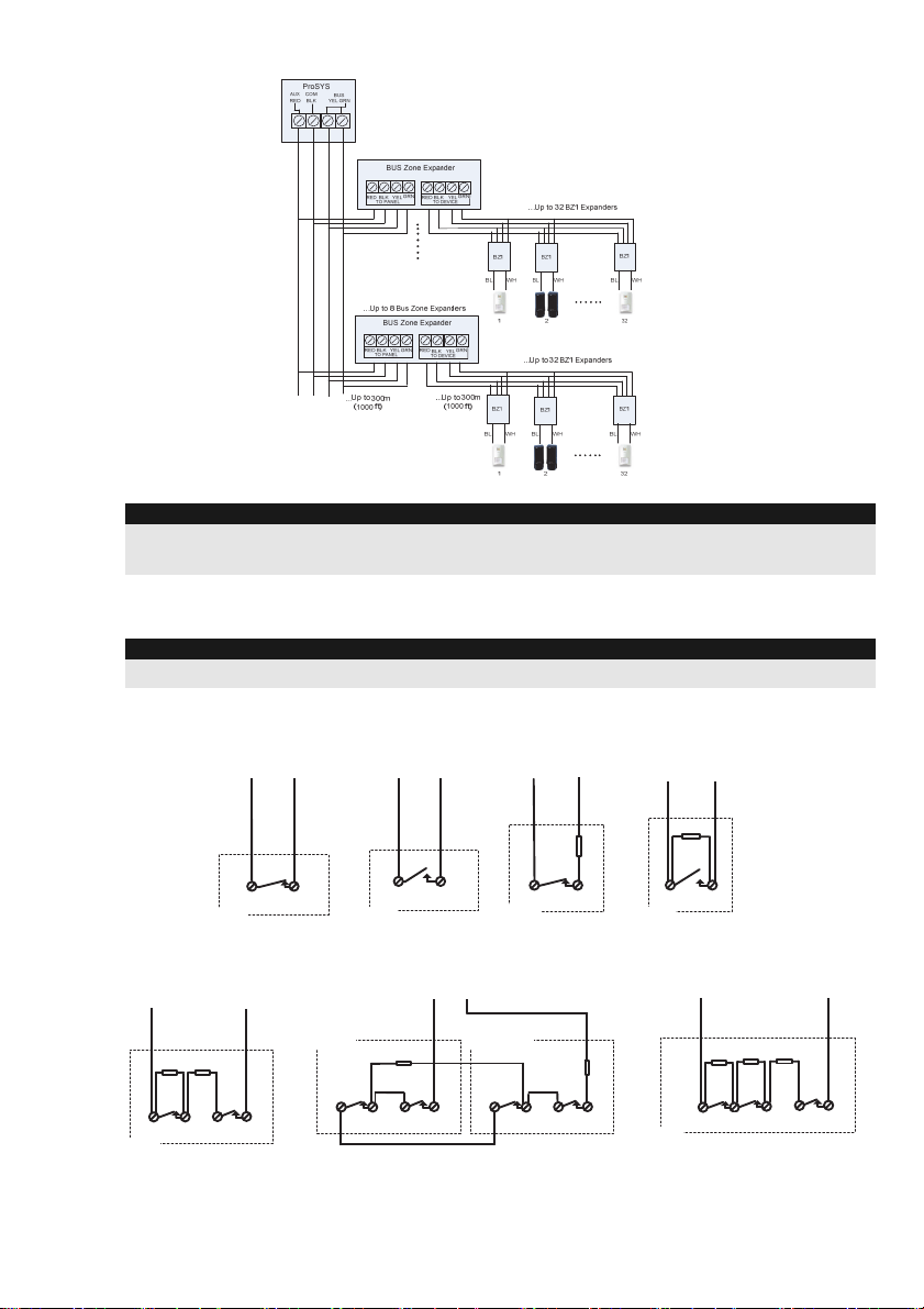
2. Wire the RP128EZ01 BUS wires Red, Black (COM), Yellow(BUS) and Green (BUS) to the
ProSYS BUS.
Notes:
For maximum operation stability, it is best NOT to exceed a total of 300 meters (1000 feet) of wiring from the
ProSYS BZ1 to the ProSYS panel or to the BUS Zone Expander.
Wiring RP128EZ01 to the Main BUS
-2-
Wiring RP128EZ01 to BUS Zones Expanders
Notes:
When connecting RP128EZ01 to a BUS Zone Expander wire the RP128EZ01 wires to the relevant BUS zone
expander's terminals marked as TO DEVICE.
3. Wire the RP128EZ01 zone wires, Black and White, to the detector's terminals according to the
required termination.
Notes:
The Black and White wires are equivalent to zone input terminals in the ProSYS.
NORMALLY OPEN ZONE
CONFIGURATION
ALARM
DETECTOR
END OF LINE ZONE
(N.C CONTACT)
4.7K
ALARM
DETECTOR
NORMALLY CLOSED
ZONE CONFIGURATION
ALARM
DETECTOR
BlackWhite BlackWhite White Black
END OF LINE ZONE
(N.O CONTACT)
ALARM
DETECTOR
4.7K
White Black
DOUBLE END OF LINE
ZONE CONFIGURATION
4.7K
ALARM TAMPER
zone
6.8K
DETECTOR
White Black
DOUBLE END OF LINE ZONE
WIRING FOR DOUBLE LEAF DOORS
6.8K
ALARM TAMPER
CONTACT 1
4.7K
ALARM TAMPER
CONTACT 2
White Black
TRIPLE END OF LINE
ZONE CONFIGURATION
(Grade 3 )
4.7K
ALARM TAMPER
6.8K
DETECTOR
White Black
12K
Fault/
AM

-3-
Programming
The following section describes the programming flow for the RP128EZ01 when connected to the ProSYS.
The RP128EZ01 should be configured in the system as an input zone of an iWISE Quad BUS Detector
(iQUG3).
Programming a RP128EZ01 that is wired to the Main BUS
Step 1: Adding RP128EZ01 to the Main Unit
QUICK KEYS = [7][1][9][5]:
1. From the main installer menu press [7][1][9][5] to access the BUS Zone category.
2. Using the /keys select the ID number as set by the RP128EZ01's DIP switches
(01-32)
Note:
The bottom line in the display shows "(0:yy) Type: None". In the 0:yy designation, the 0 represents that the
RP128EZ01 is on the main unit and is not assigned to a BUS Zone Expander. The yy represents the
RP128EZ01 ID number (up to 32) as set by its DIP switches.
3. Using the /keys move to the Type field. Use the key to select the
iQUG3 type.
4. Repeat steps 2 and 3 for other RP128EZ01 Expanders.
Note:
If required you can add virtual zones to the system and assign the RP128EZ01 to these zones. Virtual zones
are cost effective. They enable to use up to 32 RP128EZ01 Expanders on the main unit without adding
physical zone expanders. To add a Virtual BUS zone expander select type VBZ08 or VBZ16 when adding a
zone expander (Quick key [7][1][2]).
Step 2: Assign RP128EZ01 to a Zone ID and set its parameters
The RP128EZ01 should be configured in the system as the input of the iWISE Quad BUS detector (iQUG3).
Note:
The parameters of the RP128EZ01 are the same as any other regular wired zone in the system, with the
exception that it should be linked to one of the zones in the system.
1. From the main installer menu press [2] to enter the Zones menu.
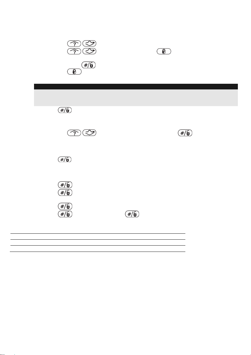
2. Using the /keys, select [ONE BY ONE] and press .
3. Using the numeric keys, enter the desired zone number and press .
Note:
You can select any zone number that is not defined on a Wireless Zone Expander or a BUS Zone Expander.
4. Press to access the Partitions category.
5. Define Partitions, Groups, Zone Type and Zone Sound.
6. In the Termination category select one of the following options: BUS Zone Input N/C, BUS
Zone Input EOL, BUS Zone Input DEOL, BUS Zone Input N/O, BUS Zone Input TEOL.
Press .
7. Press . Select the iQUG3 (0:yy) that the ProSYS BZ1 belongs to. The Type field will
be updated automatically when selecting the zone.
8. Press . Define the loop response time.
9. Press , assign a label and press .
10. Repeat steps 3-10 for all required ProSYS BZ1 expanders.
-4-
Programming a RP128EZ01 Wired to a BUS Zone Expander
Step 1: Adding the BUS Zone Expander to ProSYS
QUICK KEYS = [7][1][2]
1. From the main installer menu press [7][1][2] to enter the Add BUS zone expander menu.
2. Using the /keys select a BUS Zone Expander ID.
3. Using the /keys move to Type. Use the key to select a type (BZE08,
BZE16, BZE24 or BZE32 zone expander) based on the DIP switches you set on the
expander. Press .
4. Using the key, select type iQUG3 for any RP128EZ01 connected to this BUS zone
expander.
Note:
The display shows "(x:yy) Type: None" . In the x:yy designation, the x represents the BUS Zone Expander ID
number and the yy represents the RP128EZ01 ID number that is connected to the zone expander, as set by
the RP128EZ01 's DIP switches.
5. Press to move to the next RP128EZ01.
Step 2: Assign BUS Detectors to a Zone ID and set basic parameters
1. From the main installer menu press [2] to enter the Zones menu.
2. Using the /keys, select [ONE BY ONE] and press .
3. Using the numeric keys, select a zone number whose designation (x:yy) is equivalent to
the one defined for the ProSYS BZ1. (The x represents the BUS Zone Expander ID number
and the yy represents the ProSYS BZ1 ID number as set by its ID DIP switches).
Press to access the Partitions category.
4. Define Partitions, Groups, Zone Type and Zone Sound.
5. In the Termination category select one of the following options: BUS Zone Input N/C, BUS
Zone Input EOL, BUS Zone Input DEOL, BUS Zone Input N/O, BUS Zone Input TEOL.
Press
6. Press . Select the iQUG3 (x:yy) that the RP128EZ01 belongs to. The Type field will
be updated automatically when selecting the zone.
7. Press . Define the loop response time.
8. Press , assign a label and press .
9. Repeat steps 3-10 for all required RP128EZ01 expanders
Technical Specifications
Power Supply 13.8V
Current Consumption 20mA
Operating Temperature -10◦- 55◦C (14◦F – 131◦F)
EMC Statement
Hereby, RISCO Group declares that this equipment is in compliance with the essential requirements and other relevant
provisions of Directive 2014/30/EU.
For the CE Declaration of Conformity please refer to our website: www.riscogroup.com.
Contacting RISCO Group
RISCO Group is committed to customer service and product support. You can contact us through our website
www.riscogroup.com or as follows:
United Kingdom
Tel: +44-161-655-5500
support-uk@riscogroup.com
France
Tel: +33-164-73-28-50
support-fr@riscogroup.com
Italy
Tel: +39-02-66590054
support-it@riscogroup.com
Belgium (Benelux)
Tel: +32-2522-7622
support-be@riscogroup.com
China (Shanghai
Tel: +86-21-52-39-0066
support-cn@riscogroup.com
Spain
Tel: +34-91-490-2133
support-es@riscogroup.com
USA
Tel: +1-631-719-4400
support-usa@riscogroup.com
Israel
Tel: +972-3-963-7777
support@riscogroup.com
All rights reserved.
No part of this document may be reproduced in any form without prior written permission from the publisher.
© RISCO Group 12/2018 5IN1110 B
Table of contents
Other Risco Extender manuals


