Rise RS586 ALL-IN-ONE PC BOX User manual

RS586 ALL-IN-ONE PC BOX
USER’s MANUAL

RS586 ALL-IN-ONE PC BOX
SiS 530,5595 Socket 7 Motherboard
Onboard VGA, Sound, LAN, USB, TV-Out
Watch Dog, Disk On Chip
l
NOTICE !!! :
1. RS586 supports the voltage of 110V and 220V, so please check the
backside of PC BOX.
2. TV-Out : User can get TV-Out by insert AV or S-Video line to RS586’s AV
or S-Video, but can not insert them at the same time. Regarding the TV
mode, user can change the mode by “BIOS SETUP –INTEGRATED
PERIPHERALS –TV mode selection (+/-/PU/PD to modify: CRT+NTSC U,
CRT+NTSC O, CRT+PAL U, CRT+PAL O, CRT Only.” (press “DEL” into
BIOS SETUP when system boot up).
3. Sound output by “SPK OUT” in the backside.
4. User must read each ”Readme.txt” in sub-directories before installing
required drivers(VGA, Sound, LAN, IDE). IDE can support DMA66 by
install SiS IDE dirver.
Manual, version 1.2
Motherboard, version B2
CD Driver, version B1
Modified in 2002.03.25

Introduction
RS586 is an ALL-IN-ONE PC (3 IN 1) SYSTEM
1. LAN STATION : Compose into Internet (Intranet) by linking with server
based on low cast.
2. BOOK PC : 30.5cm x 23.5cm x 5cm (Case Dimension)
3. SET-TOP BOX : Provide TV-Out function to be family internet station.
About This User's Guide
This User's Guide is for assisting system manufacturers and end
user in setting up and installing the mainboard. Information in this
guide has been carefully checked for reliability; however, there may
still be inaccuracies and information in this document is subject
to change without notice.
DISCLAIMER
The information in this manual has been carefully checked and is
believed to be accurate. We assume no responsibility for any
inaccuracies that may still be contained in this manual. We
reserve the right to make changes to this material at any time
without notice.
REMARK
Intel Pentium is a registered trademark of Intel Corp.
All other trademarks mentioned in this manual are registered
property of the respective owners.
RS586 Website ( http://www.rise.com.tw )

Table of Contents
Chapter 1 INTRODUCTION
1.1 Preface………………………………………………………..…………………. 1-1
1.2 Key Features…………………………………………………………………… 1-1
1.3 Unpacking………………………………………………………………………. 1-3
1.4 Notice of CD Driver Installation…………………………………………….. 1-3
Chapter 2 HARDWARE INSTALLATION
2.1 Jumper Setting Summary…………………………………………………… 2-1
2.2 System & Motherboard Layout…………………………………………….. 2-3
2.3 Serial Hard Disk Installation………………………………………………… 2-5
2.4 Motherboard Jumper Setting……………………………………………….. 2-6
2.5 Connectors…………………….………………………………………………. 2-13
Chapter 3 BIOS SETUP
3.1 Standard CMOS Setup……………………………………………………….. 3-1
3.2 BIOS Features Setup…………………………………………………………. 3-3
3.3 Chipset Features Setup………………………………………………………. 3-6
3.4 Power Management Setup…………………………………………………… 3-9
3.5 PNP/PCI Configuration………………………………………………………. 3-15
3.6 Integrated Peripherals……………………………………………………….. 3-18
3.7 Load BIOS Defaults……………………………………….………………….. 3-22
3.8 Load Setup Defaults……………………………………….…………………. 3-22
3.9 IDE HDD AUTO Detection……………………………………………………. 3-23
3.10 SAVE & EXIT Setup………………………………………………………….. 3-23
3.11 EXIT Without Saving………………………………………………………… 3-23
3.12 Flash BIOS…………………………………………………………………….. 3-23
All other trademarks mentioned in this manual are registered property of the
respective owners.

_________________________________
【
1
】
1. INTRODUCTION
1.1 Preface
Thanks for choosing the RS586 ALL-IN-ONE PC BOX. This
manual explains how to use this product and install upgrades.
It has an overview of the design and features of the board and
provides useful information on the configuration of the board, or
the system in which, it is installed.
1.2 Key Features
Processor : Supports Socket 7 processors, AMD K6-2/3, Cyrix MII, Intel Pentium.
Chipset : SiS 530, 5595 Chipset.
Expansion Slot : One 32-bit PCI Bus Master Mode Slot
( Support two PCI slots on Riser card ).
Cache Memory : 512K cache.
System Memory : Supports 2 x 168-pin DIMM Sockets (2 Banks)
-The Memory from 32MB up to 512MB (SDRAM)
On Board IDE : 2 x IDE Connectors for up to 4 IDE Drives.
-PIO Mode 4 transfers
-Support Ultra DMA 33/66
On Board I/O : 2 Serial Port Connectors (16550 Fast UART compatible).
-1 Parallel Port Connectors (EPP/ECP capability).
-1 Floppy Disk Connector.
-1 PS/2 Mouse Connector.
-1 PS/2 Keyboard Connector.
-1 IrDA Connector.
On Board VGA : Built-in SiS 530 AGP 3D-Graphics shared
memory to 2/4/8MB.
On Board TV-Out : Built-in Chrontel 7003 chip (S-VIDEO & RCA jack output).
On Board Sound : Built-in ForteMedia FM801-AS PCI 3D Sound chip.
On Board LAN : Built-in RTL8139C 100BASE-TX PCI Lan chip.
______________________________________________________________
1-1

【
1
】
________________________________
Watch Dog : Can be set by 500ms, 1, 2, 4 seconds period.
RESET or NMI was generated when CPU did
not periodically trigger the timer.
Disk On Chip : 100% Hard Disk and DOS compatible, no need
extra software utility. One 32-pin socket.
On Board USB : Universal Serial Bus Controller.
-Host / HUB Controller.
-Two USB Port connectors.
BIOS : Flash ROM BIOS with Green, Plug and Play Features.
Dimension : Special Form Factor Size.
23cm x 22cm or 9.1" x 8.7" (4 Layers)
CASE Dimension : 30.5cm x 23.5cm x 5cm
______________________________________________________________
1-2
_________________________________
【
1
】
1-3 Unpacking :
The system package should contain the following:
lThe RS586 ALL-IN-ONE PC BOX.
lUSER'S MANUAL for RS586 system.
lCable for IDE, I/O device.
lPower Line x 1
lDriver for IDE,VGA, Audio, LAN(CD) .
lComponents for PCBOX.
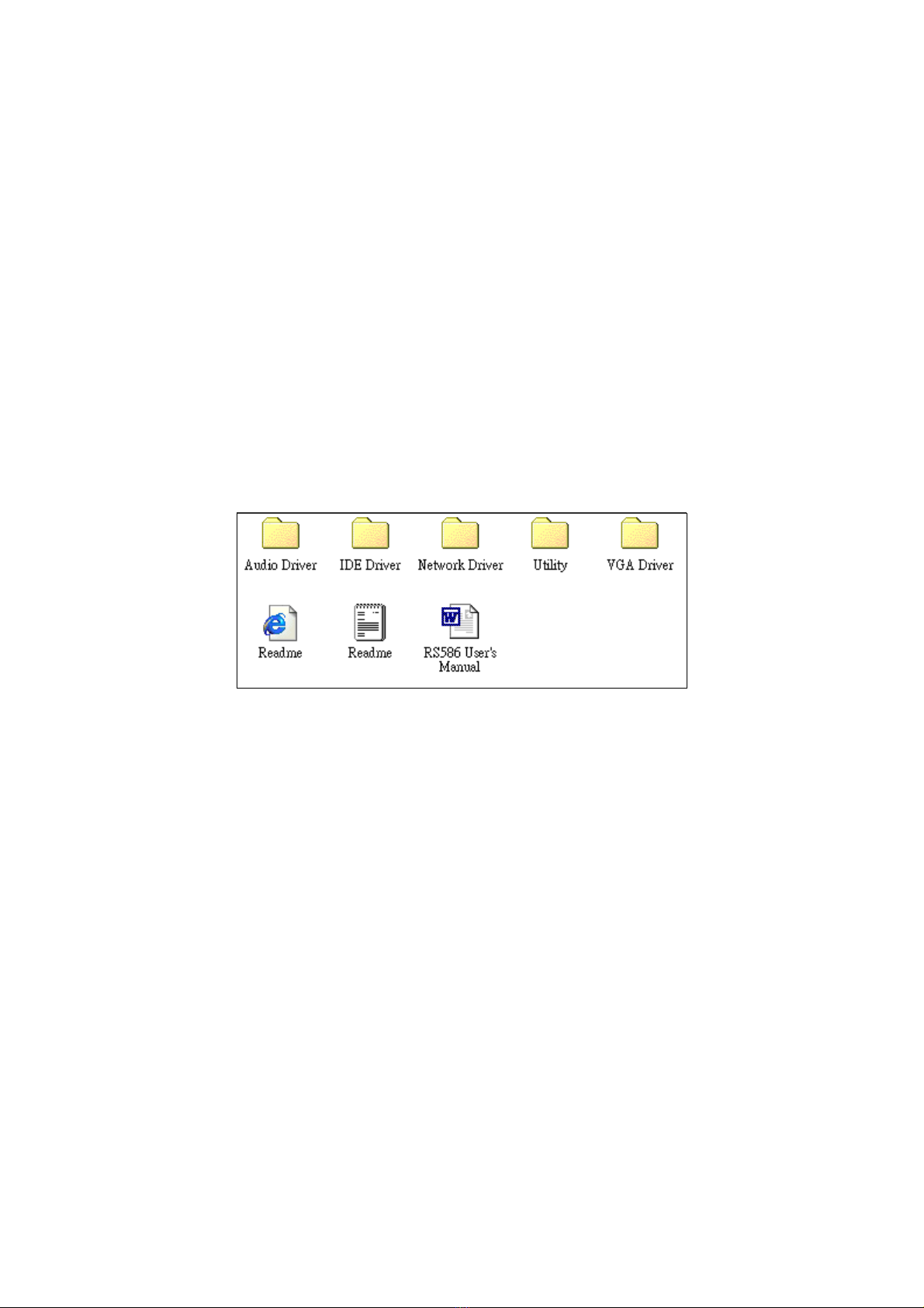
1-4 Notice of CD Driver Installation
This CD contains the following drivers. The user must read each ”Readme.txt” in sub-
directories before installing required drivers.
[Audio Driver] : ForteMedia FM801 Driver.
[IDE Driver] : SiS 530/5595 IDE Driver for DMA 33/66.
[Network Driver] : Realtek 8139B Driver.
[VGA Driver] : SiS 530 VGA Driver.
[Utility] : SiS chipset utility.
Company Website ( download latest driver...... )
SiS
530/5595 : www.sis.com.tw ( VGA & IDE Driver )
REALTEK
Rtl8139B : www.realtek.com.tw ( Network Driver )
ForteMedia
FM801 : www.fortemedia.com ( Audio Driver )
DirectX
: www.microsoft.com
BIOS Download : www.rise.com.tw
______________________________________________________________
1-3
_________________________________
【
2
】
2. HARDWARE INSTALLATION
This chapter explains how to configure the system hardware.
Refer to this chapter whenever you upgrade or reconfigure your system.
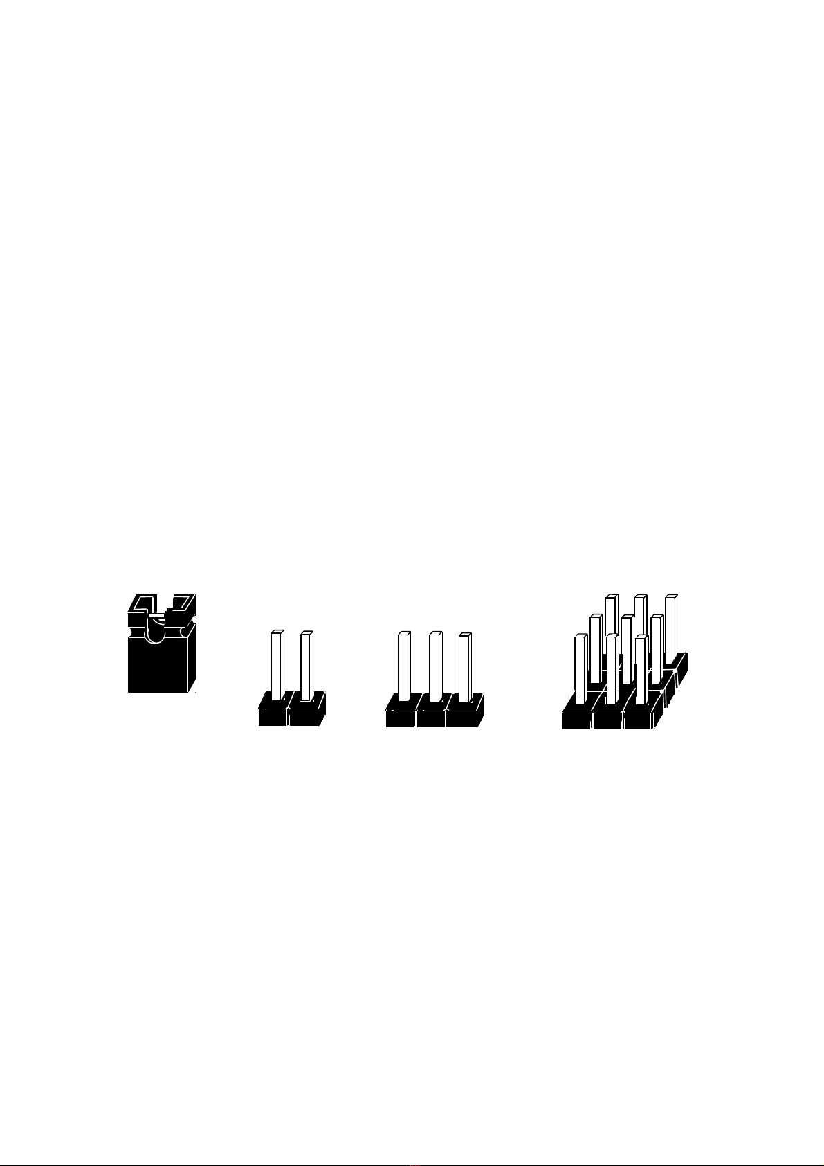
2.1 Jumper Setting Summary :
Regarding hardware settings on the board. They specify configuration options
for various features. The settings are made using something called a "Jumper". A jumper is
a set of two or more metal pins in a plastic base attached to the mainboard. A plastic jumper
"cap" with a metal plate inside fits over two pins to create an electrical contact between them.
The contact establishes a hardware setting.
Some jumpers have two pins, other have three or more. The jumper are sometimes combined
into sets called jumper "blocks", where all the jumpers
in the block must be set together to establish a hardware setting.
The next figures show how this locks.
Jumpers and caps
Jumper cap 2-Pin Jumper 3-Pin Jumper Jumper block
______________________________________________________________
2-1

【
2
】
_________________________________
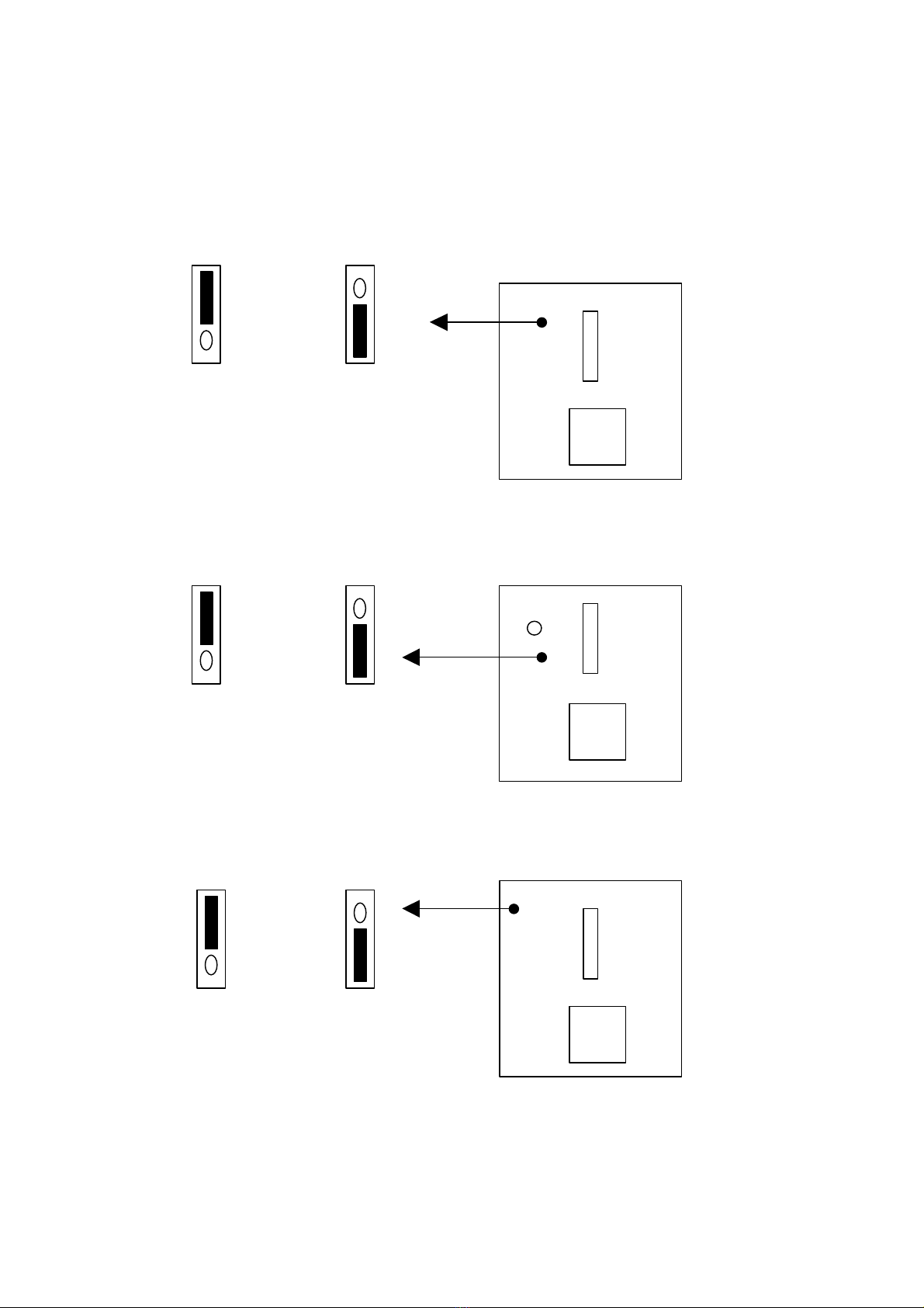
Most jumper setting are printed on the board in a stylized bird's-eye view,
with which pins to connect for each setting marked by a bar connecting two
pins. For example, if a jumper has three pins, connecting or "closing",
the first and second pins creates one setting and closing the second and
third pins creates another. The same type of diagrams are used in this
manual. The jumpers are always shown from the same point of view as
shown in the whole board diagram in this chapter.
Jumpers diagrams
Jumper caps like this
Jumpers are shown like this
Jumper settings like this
1
3
(Pin 1 & 2 Close)
( Open )
※The Red colors Jumper for system Voltage setting, please careful to change it.
______________________________________________________________
2-2

_________________________________
【
2
】
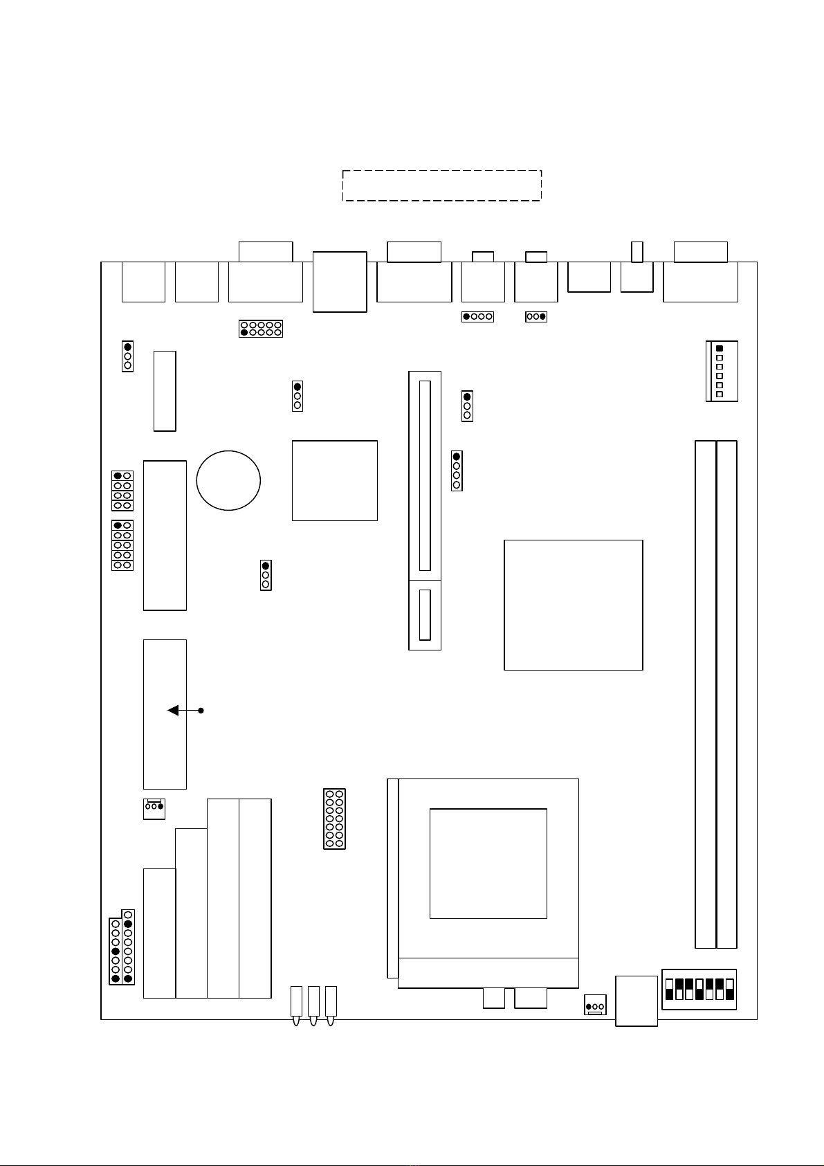
2.2 System & Motherboard Layout :
RS586 System Layout
LED
PW : Green color. HD : Red color. LAN : Yellow color.
________________________________________________________________
2-3
[ FRONT ]
USB Port
PW
LAN
HD
Power
Socket
VGA
110V
220V
AV
S-Video
SPK OUT
MIC
COM2
LAN COM1 Mouse KB
[ BACK ]
Power
Switch
TV-OUT
FAN
【
2
】
_________________________________
________________________________________________________________
2-4
COM2
LAN VGA
SiS
5595
SiS
530
KB MOUSE
MIC
SPK OUT
CD1
S-Video
AV
SPK _IN
USB
PW1
JP1
JP2
JP6
JP3
JP5
Watch
DOG
JP4
JP7
B
I
O
S
FAN2
JP8
Battery
P
A
N
E
L
FAN1
GAL2008
F
D
D
1
L
P
T
1
I
D
E
2
I
D
E
1
SW1
DIMM1 / DIMM2
P
W
COM1
Disk
On
Chip
RS586 Motherboard Layout
H
D
L
A
N
USB
LED
_________________________________
【
2
】
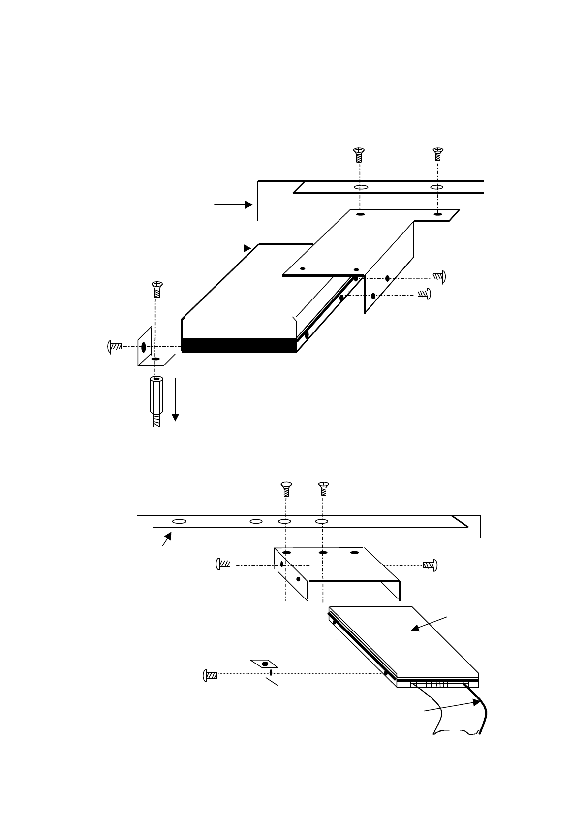
2.3 RS-586 Serial Hard Disk Installation
(1) 3.5
“
HDD INSTALL
Case
Cable side
(2) 2.5
”
HDD INSTALL
________________________________________________________________
2-5
To M/B
HDD
Cable
CASE
HDD

【
2
】
_________________________________
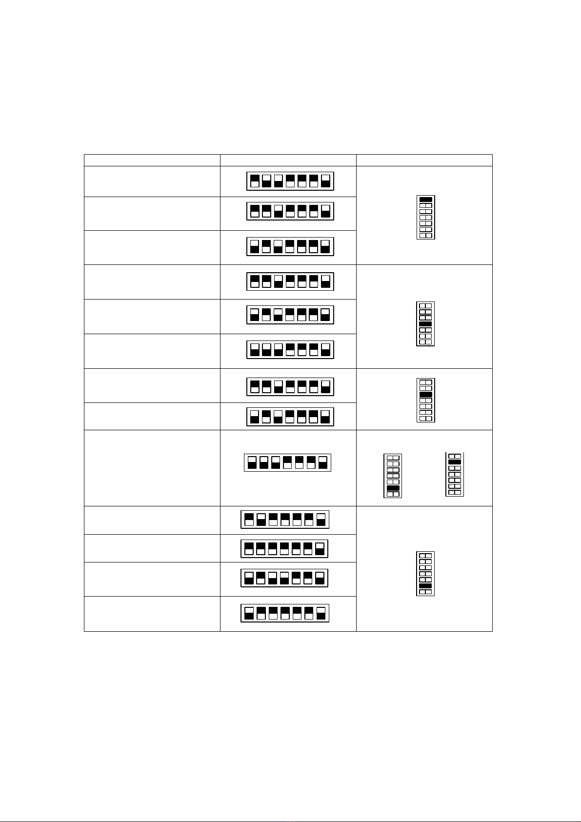
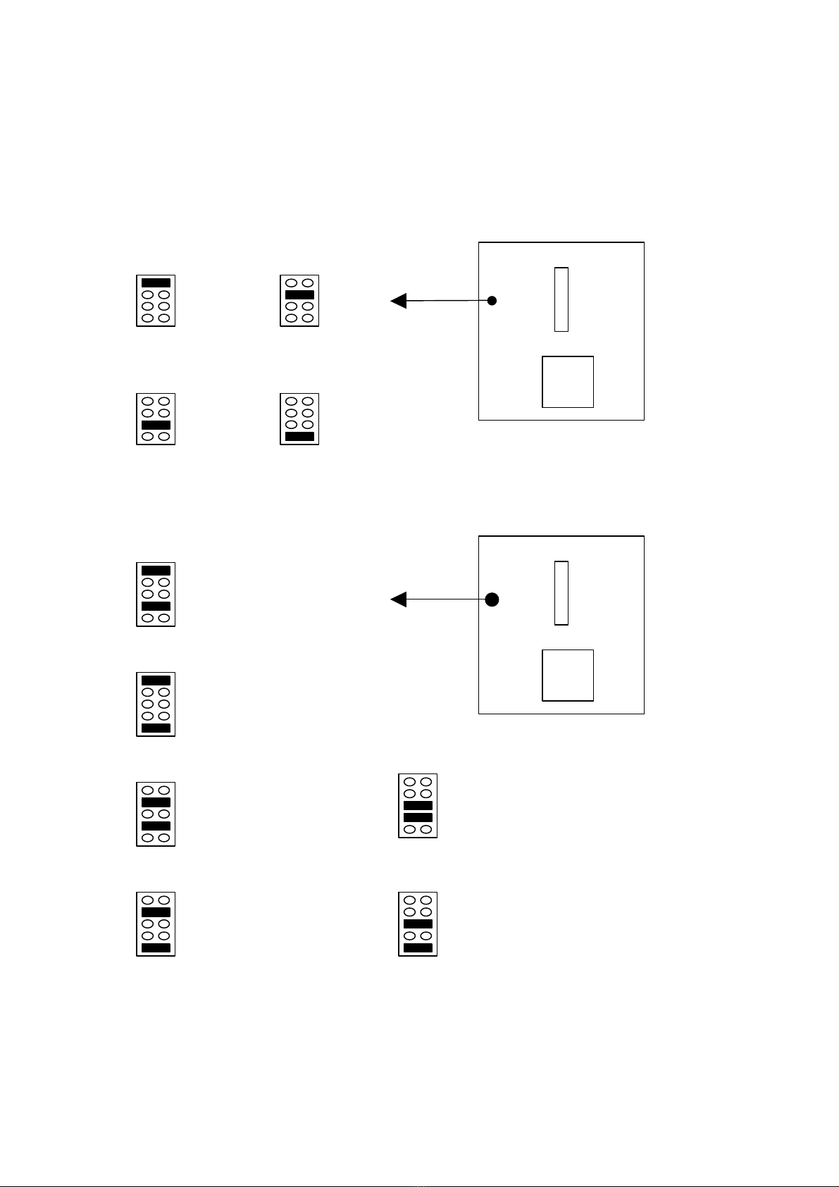
2.4 Jumper Setting :
CPU Clock Selector : SW1
CPU Power Voltage Selector : JP8
________________________________________________________________
2-6
SW1CPU Type
123
X 2.0 ON OFF OFF
X 2.5 ON ON OFF
X 3.0 OFF ON OFF
X 3.5 OFF OFF OFF
X 4.0 ON OFF ON
X 4.5 ON ON ON
X 5.0 OFF ON ON
X 5.5 OFF OFF ON
SW1CPU Bus
Clock 4567
66 MHz ON ONON OFF
75 MHz ON ON OFF OFF
83 MHz ON OFF ON OFF
90 MHz ON ON OFF ON
95 MHz ON OFF OFF OFF
100 MHz OFF ON ON OFF
2.2v
2.4v
2.1v
2.8v
2.9v
3.2v
3.5v
1 2 3 4 5 6 7
ON
OFF
_________________________________
【
2
】
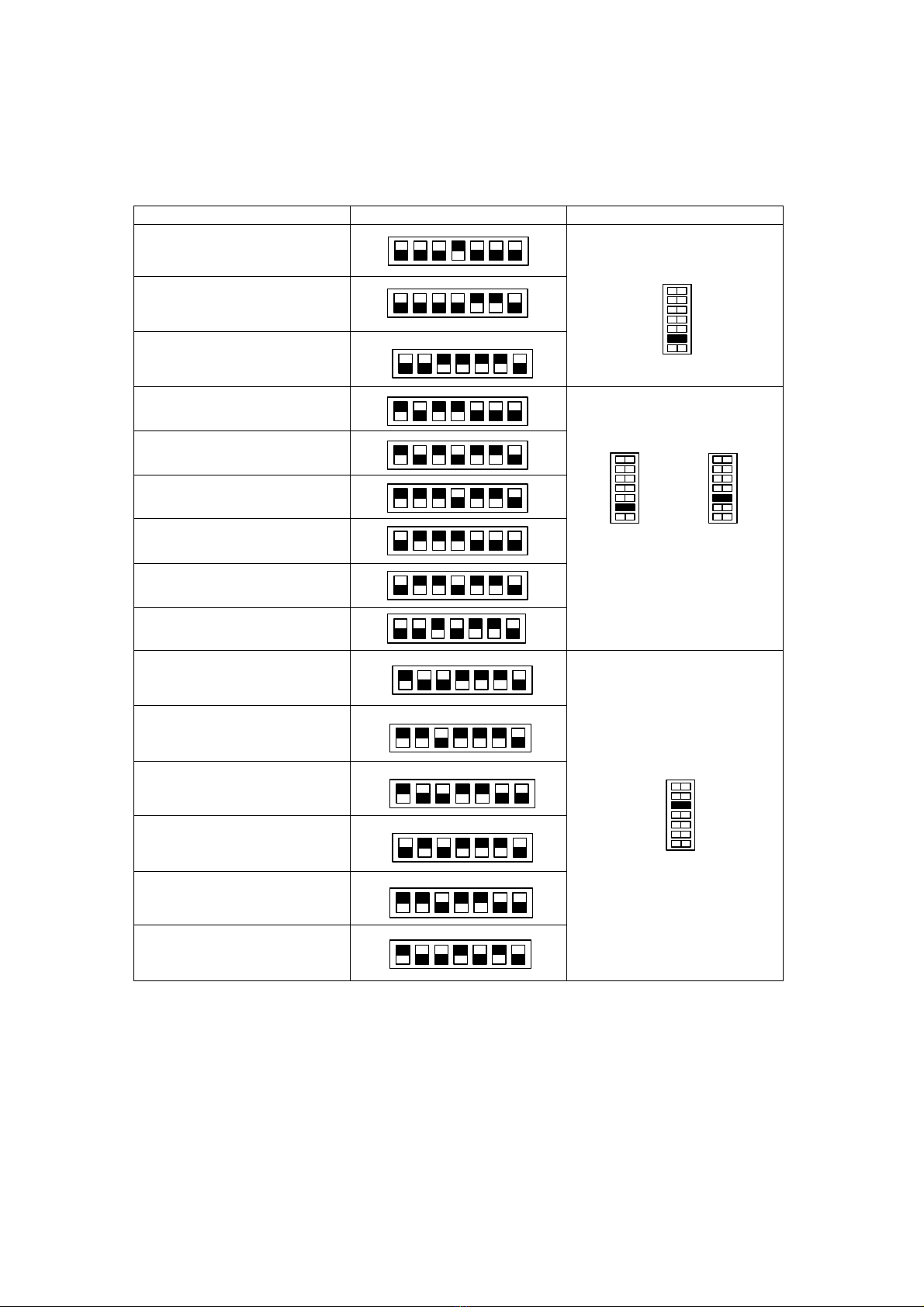
Quick Installation Guide :
CPU SW1 Voltage
Intel Pentium® 133MHz
66MHz x 2
Intel Pentium® 166MHz
66MHz x 2.5
Intel Pentium® 200MHz
66MHz x 3
Intel MMX 166MHz
66MHz x 2.5
Intel MMX 200MHz
66MHz x 3
Intel MMX 233MHz
66MHz x 3.5
AMD K6 166MHz
66MHz x 2.5
AMD K6 200MHz
66MHz x 3
AMD K6 233MHz
66MHz x 3.5
OR
AMD K6/K6-2 266MHz
66MHz x 4
AMD K6 300MHz
66MHz x 4.5
AMD K6/K6-2 300MHz
100MHz x 3
AMD K6-2 333MHz
66MHz x 5
________________________________________________________________
2-7
2.9v
3.5v
2.8v
3.2v
2.2v
2.2v
【
2
】
_________________________________
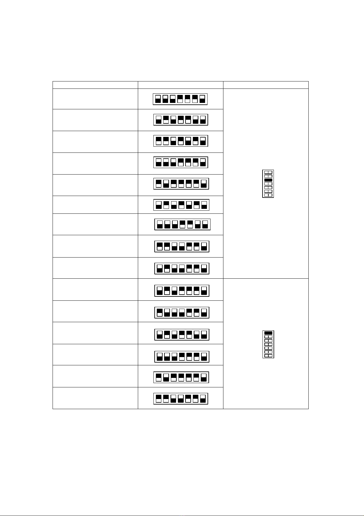
CPU SW1 Voltage
AMD K6-2 333MHz
95MHz x 3.5
AMD K6-2 350MHz
100MHz x 3.5
AMD K6-2 366MHz
66MHz x 5.5
AMD K6-2 380MHz
95MHz x 4
AMD K6-2/3 400MHz
100MHz x 4
AMD K6-2/3 450MHz
100MHz x 4.5
AMD K6-2/3 475MHz
95MHz x 5
AMD K6-2/3 500MHz
100MHz x 5
AMD K6-2/3 550MHz
100MHz x 5.5
OR
Cyrix/IBM PR 166MHz
66MHz x 2
Cyrix/IBM PR 200MHz
66MHz x 2.5
Cyrix/IBM PR 200MHz
75MHz x 2
Cyrix/IBM PR 233MHz
66MHz x 3
Cyrix/IBM PR 233MHz
75MHz x 2.5
Cyrix/IBM PR 233MHz
83MHz x 2
________________________________________________________________
2-8
2.2v
Power Voltage
Request on CPU’s
Surface.
2.2v
2.9v
2.4v
_________________________________
【
2
】
CPU SW1 Voltage
Cyrix/IBM PR 266MHz
66MHz x 3.5
Cyrix/IBM PR 266MHz
75MHz x 3
Cyrix/IBM PR 266MHz
83MHz x 2.5
Cyrix MII PR 300MHz
66MHz x 3.5
Cyrix MII PR 333MHz
66MHz x 4
Cyrix MII PR 333MHz
83MHz x 3
Cyrix MII PR 333MHz
75MHz x 3.5
Cyrix MII PR 366MHz
100MHz x 2.5
Cyrix MII PR 400MHz
100MHz x 3
IDT Winchip 2 200MHz
66MHz x 3
IDT Winchip 2 200MHz
100MHz x 2
IDT Winchip 2 225MHz
75MHz x 3
IDT Winchip 2 233MHz
66MHz x 3.5
IDT Winchip 2 266MHz
66MHz x 4
IDT Winchip 2 300MHz
100MHz x 2.5
________________________________________________________________
2-9
2.9v
3.5v
【
2
】
_________________________________
*The Default (include CPU) setting is 100MHz x 5 at 2.2v
for AMD K6-2 500MHz.
Onboard Sound Selector : JP1
________________________________________________________________
2-10
CPU SW1 Voltage
AMD K6-2 500MHz
2.2v
1-2 close
Enable
Sound
(default)
2-3 close
Disable
Sound
_________________________________
【
2
】
Onboard LAN Selector : JP3
CMOS Selector : JP5 (Clear CMOS : 2-3 short 5 seconds then 1-2 short)
Watch-DOG Time out Selector : JP4
________________________________________________________________
2-11
1-2 close
Enable
LAN
(default)
2-3 close
Disable
LAN
1-2 close
Normal
(default)
2-3 close
Clear
CMOS
1-2 close
IOCHK#
(default)
2-3 close
PWRGD
【
2
】
_________________________________
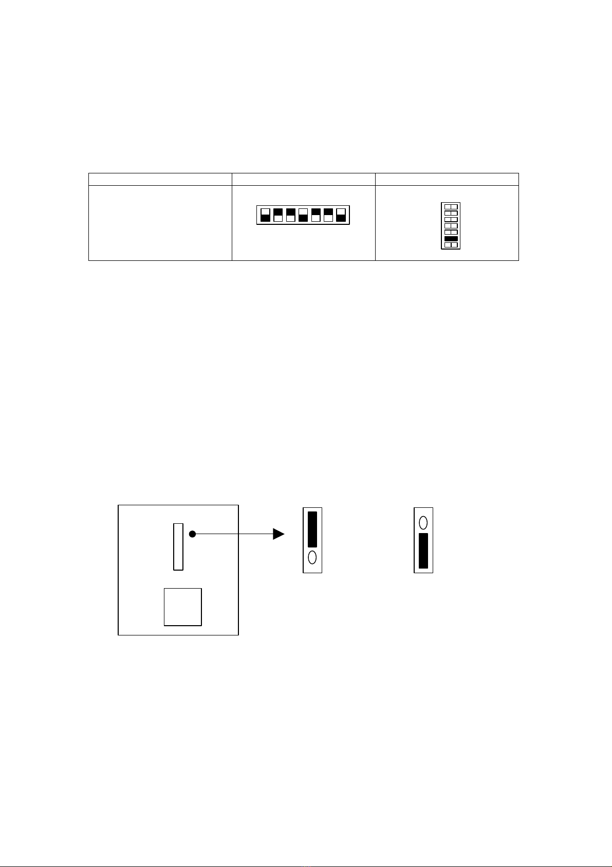
Watch-DOG Timing Selector : JP6
Disk On Chip Address Selector : JP7
________________________________________________________________
2-12
500 ms 1 Sec
2 Sec 4 Sec
0C800H –0C9FFH
0CC00H –0CDFFH
0D000H –0D1FFH
0D400H –0D5FFH
0D800H –0D9FFH
0DC00H –0DDFFH
_________________________________
【
2
】
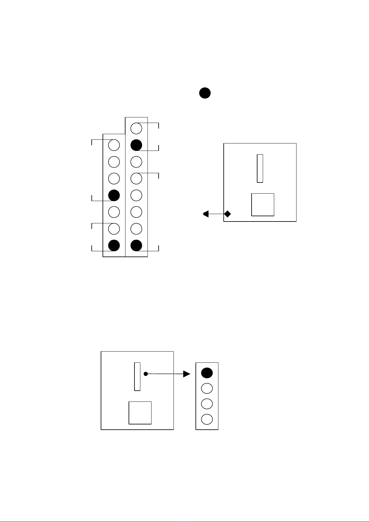
2.5 Connectors (PANEL):
Connector : J2, J3
Connector JP2 : 2nd PCI Riser Card Conn.
________________________________________________________________
2-13
= Pin 1 or “ + “
PCICLK2
PREQ#1
PGNT#1
R_AD21
Turbo LED
IR
Connector
Speaker
Reset
Table of contents
Other Rise Motherboard manuals


