Risen RSM60-6 P Series Instruction Manual

RISEN ENERGY CO., LTD. (DOCUMENT)
R
RISEN ENERGY CO., LTD. (DOCUMENT)
RISEN PV MODULE INSTALLATION
AND MAINTENANCE MANUAL
DOCUMENT NO.
RS/03-MR-01-2021
COMPILER
Chen shuilin
EDITION
A/0[2021]
REVIEWER
Zhang Shengcheng
DISTRIBUTION NO.
APPROVER
Liu Yafeng
STATUS
STAMP
THIS DOCUMENT HAS A TOTAL OF *34* PAGES INCLUDING THE FRONT COVER
ISSUE DATE 2021-02-01 IMPLEMENTATION DATE 2021-02-01
2021 .【Risen】

2
RS/03-GT-016-2019 Date: 2021-02-01
DESCRIPTION OF AMENDMENT
DATE
EDITION
CHAPTER
AMENDED CONTENTS
RECORDER
2018.04
A/0
Full Text
Installation manual instructions
Chen Shuilin
2018.11
A/0
Chapter 8
Add module specifications, update the content
Bai Wenkai
2019.01
A/0
Full Text
Updates the content
Liu Fengmin
2019.02
A/1
Chapter 8
Add bolting method for bifacial dual-Glass modules
Chen Shuilin
2019.04
A/1
Chapter 8
Add 158.75 Cell module type; Update mounting hole
position
Chen Shuilin
2019.06
A/2
Chapter
2,8,11
Add Added heterojunction module type, update the content
Chen Shuilin
2020.03
A/1[2020]
Chapter
3,4,8
Add RSMxxx-8 PV module model,Update the installation
diagram, add the flat single shaft installation method, and
delete some installation methods
Pei Shichao
2020.08
A/2[2020]
Chapter 7,8,
9
Add seaside installation requirements for module,
installation method of flat single shaft, delete part of the
models in the short side installation form, and add force
requirements for the installation of connectors ,add
RSM144-6 frame 25mm module load
Pei Shichao
2020.11
A/3[2020]
Chapter
1,7,8
Delete some PV module models、update the requirements
for seaside installation of salt spray-resistant modules、
change the expression of module models、add RSM144-9、
RSM120-8 PV module
Pei Shichao
2021.02
A/0[2021]
Chapter
2,4,6,
7,8,9,12
Add the guidance of recycling and disposal of waste PV
modules after quality assurance, cold shrinkable pipe
fittings of salt spray-resistant modules and installation of
double glass beams; Update bracket load, no beam load,
add steel frame PV modules, 210 series PV modules,
Single and double glass installation manuals are integrated
Chenshuilin
REQUIREMENTS: THIS DOCUMENT SHALL BE REVIEWED AND EVALUATED BY LEADING DEPARTMENT AT
LEAST ONCE A YEAR, AND UPDATES SHALL BE MADETO ENSURE THE PRACTICABILITY OF THE DOCUMENT
WHEN IT IS NECCESARY.
DOCUMENT COUNTERSIGN
DEPARTME
NT
NAME
CEO’s office
Quality and
global
customer
service
Technical
compliance
Global
customer
service
PV module R
& D center
Quality
managemen
t
COUNT
ERSIGN
ER
Xie jian
Hu
yuhui
Song
Yifeng
Chen
Xiaoxu
Liu
yafeng
Qian
juncen

3
RS/03-GT-016-2019 Date: 2021-02-01
1. PURPOSE
This manual provides relevant information on the installation and safe use of PV modules produced
by Risen Energy Co., Ltd and Risen Energy (CHANGZHOU) Co., Ltd. (hereinafter referred to as Risen
Energy or Risen), and recommends safe and reliable module installation and maintenance instructions for
our customers.
Before installation, the installer must read and understand this manual. If you have any questions,
please contact sales or customer service staff of Risen for further understanding. When installing, the
installer shall comply with all safety precautions and installation laws and regulations in this manual. The
installation personnel should be familiar with the mechanical load and electrical requirements of the
installation system, and Risen has the right to refuse to compensate for the damage of the modules caused
by the operation reasons or design defects of the power generation system.
2. SCOPE
This document is applicable to the installation of bifacial modules of Risen Energy Co., Ltd. (including
all factories).
3. OBLIGATIONS
PV Module R&D Center: responsible for the preparation, update and maintenance of this document.
4. REFERENCES
NO
5. DEFINITIONS
NO
6. PROCEDURE
NO
7. RELEVANT RECORDS AND SHEETS
See document resume.
8. SUPPLEMENTARY PROVISIONS
The PV Module R&D Center reserve the final right to interpret this document. If there is no controlled
seal on the document or any part of it is missing, this document will be invalid. Something that violate the
management of documents is prohibited for any department or individual, such as printing, copying, and
duplicating the document. If there is any discrepancy caused by translation, the Chinese version shall
prevail.

4
RS/03-GT-016-2019 Date: 2021-02-01
CATALOGUE
1. Manual Introduction...................................................................................................................................................5
2. Applicable Products...................................................................................................................................................5
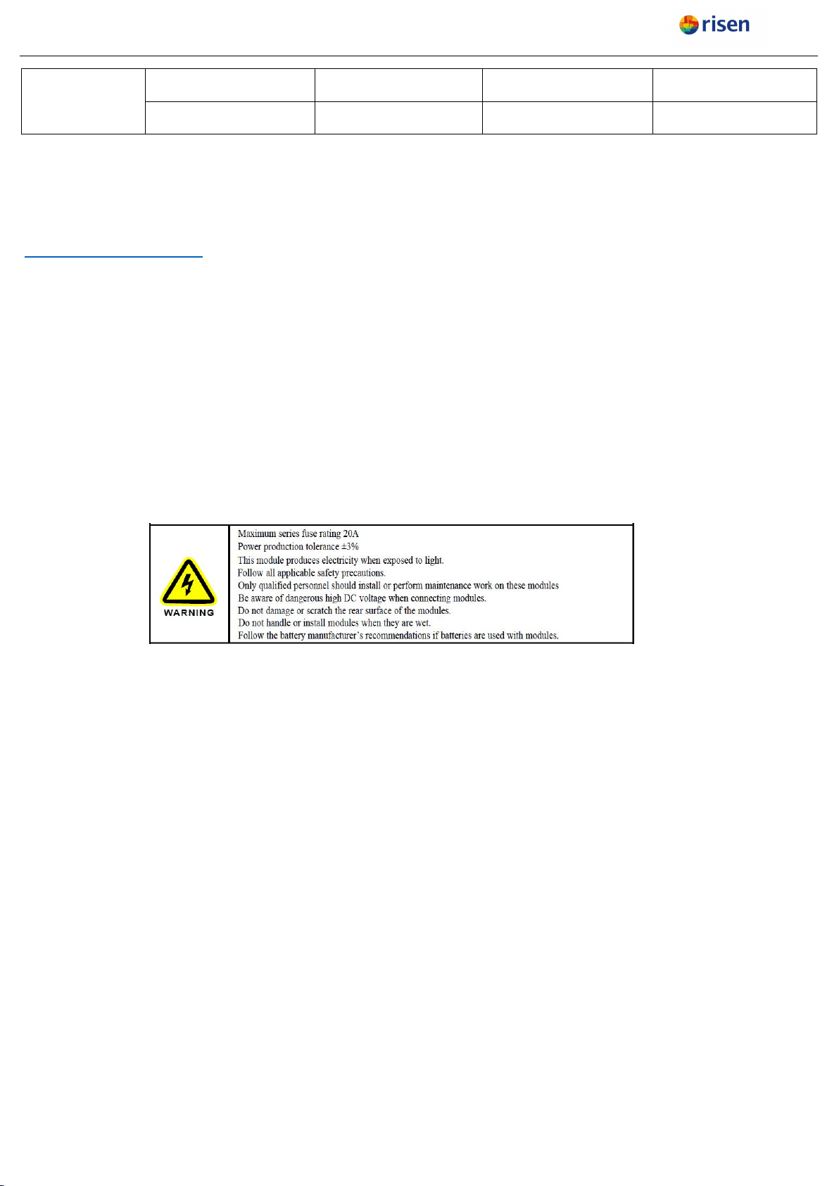
3. Warning....................................................................................................................................................................... 6
4. Safety Cautions..........................................................................................................................................................6
5. Unloading, Transportation and Storage............................................................................................................... 10
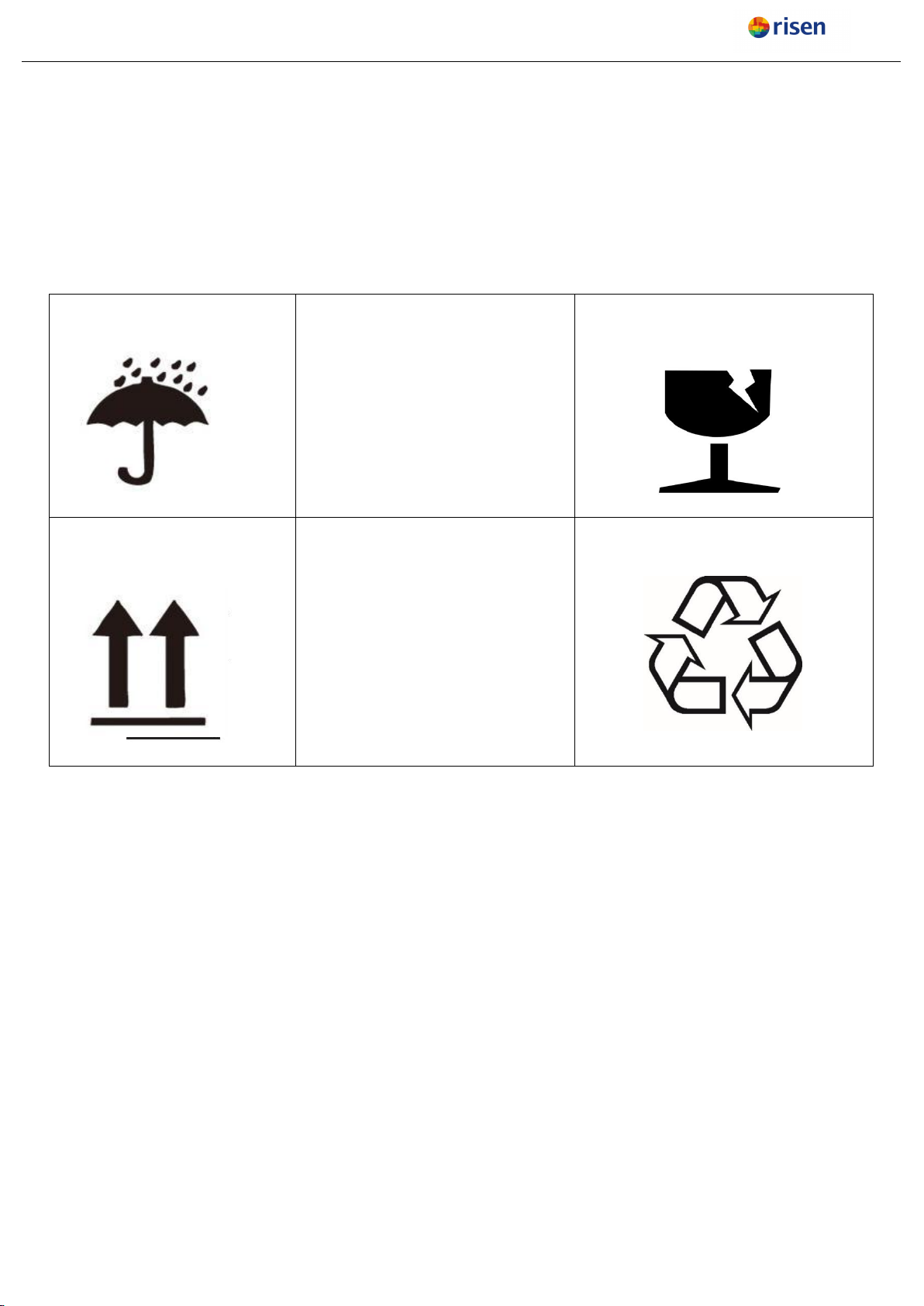
5.1. Markers on outer packaging....................................................................................................................... 10
5.2. Unloading cautions.......................................................................................................................................10
5.3. Secondary transportation and Warning.................................................................................................... 12
5.4. Storage...........................................................................................................................................................13
5.5. Markings on module.....................................................................................................................................13
6. Matters needing attention for unpacking..............................................................................................................14
7. Installation.................................................................................................................................................................14
7.1. Environment conditions and site selection............................................................................................... 14
7.2. Tilt angle of Installation................................................................................................................................ 16
7.3. Installation requirements for bifacial module............................................................................................17
8. Installation Guidelines.............................................................................................................................................18
8.1 Bolting method............................................................................................................................................... 18
8.1.1 Bolts installation:......................................................................................................................................18
8.1.2 Fixture installation:.................................................................................................................................. 19
8.1.3 Offshore PV module connector protection device.................................................................................20
8.2 Installation method of fixed support............................................................................................................21
8.3 Tracking system..............................................................................................................................................24
9. Cable layout..............................................................................................................................................................25
10. Electrical Connection............................................................................................................................................ 27
10.1 Bypass secondary.......................................................................................................................................29
11. Grounding............................................................................................................................................................... 30
12. Electrical Parameters............................................................................................................................................31
13. Inspection and Maintenance................................................................................................................................32
12.1.PV Module Recycling..................................................................................................................................32
12.2.Module visual inspection and replacement............................................................................................. 33
12.3.Cleaning........................................................................................................................................................34
14. Troubleshooting..................................................................................................................................................... 35
15. DISCLAIMER......................................................................................................................................................... 35

5
RS/03-GT-016-2019 Date: 2021-02-01
1. Manual Introduction
Thanks for choosing Solar PV modules from Risen Energy Co., Ltd (hereinafter called Risen).
In order to ensure that the PV modules are installed correctly, please read the following installation manual
carefully before modules are installed and used.
Please let the well trained professional to engage the PV module’s installation, running and maintenance
due to these works are based on the professional knowledge. The personnel for the installation should be
familiar with the mechanical and electrical requirements.
Please get contact with Risen After-service Department (Afterservice@risenenergy.com) or Risen local
agency if you want to get more details or there is any question.
2. Applicable Products
Risen’s photovoltaic solar module is a DC power supply, which has the character of high reliability and
nearly no-maintenance. It can be used in power systems of remote areas, home power systems, renewable
energy vehicles, hydropower stations, water pumps, communication system or constitute solar photovoltaic
power station directly. These systems not only can be used by battery, but also can be used by
grid-connection directly without battery.
This document is applicable to the following PV Solar Modules types:
Monofacial
modules
RSM60-6-xxxP/M
RSM72-6-xxxP/M
RSM120-6-xxxP/M
RSM144-6-xxxP/M
RSM132-6-xxxP/M
RSM156-6-xxxP/M
RSM120-7-xxxP/M
RSM144-7-xxxP/M
RSM120-6-xxxMB
RSM132-6-xxxMB
RSM144-6-xxxMB
RSM40-8-xxxP/M
RSM40-8-xxxMB
RSM90-8-xxxP/M
RSM110-8-xxxP/M
RSM120-8-xxxP/M
RSM132-8-xxxP/M
RSM150-8-xxxP/M
RSM120-9-xxxP/M
RSM132-9-xxxP/M
RSM144-9-xxxP/M
Monofacial
modules-double
glass
RSM60-6-xxx P/MDG
RSM72-6-xxx P/MDG
RSM120-6-xxxP/MDG
RSM132-6-xxxP/MDG
RSM144-6-xxxP/MDG
Bifacial module
RSM60-6-xxx BMDG
RSM72-6-xxx BMDG
RSM120-6-xxx BMDG
RSM132-6-xxx BMDG
RSM144-6-xxx BMDG
RSM144-6-xxx
BMDGZ
RSM120-7-xxxBMDG
RSM144-7-xxxBMDG
RSM144-7-xxx
BMDGZ
RSM90-8-xxxBMDG
RSM110-8-xxxBMDG
RSM120-8-xxxBMDG
RSM132-8-xxxBMDG
RSM150-8-xxxBMDG
RSM120-9-xxxBMDG
RSM132-9-xxxBMDG
RSM144-9-xxxBMDG

6
RS/03-GT-016-2019 Date: 2021-02-01
HIT- Bifacial
module
RSM60-6-xxx BHDG
RSM72-6-xxx BHDG
RSM120-6-xxx BHDG
RSM132-6-xxx BHDG
RSM144-6-xxx BHDG
RSM156-6-xxx BHDG
The Solar PV modules described in this manual are terrestrial used only, cannot be used in space. The high
altitude influence to module operation should be considered when the modules are installed in high altitude
area.。
3. Warning
Please read and understand all the safety cautions before the PV module installation, wiring, operation and
maintenance. When exposed to the sun light or other light sources directly, the PV modules will generate
the Direct Current, there will be the risk to cause people death when touching the electrical part like the
connectors/terminals no matter whether the modules are connected or not
4. Safety Cautions
In the installation and maintenance, all the Safety Cautions mentioned in this manuals should be followed,
in the meantime, all the requirements defined by local law, authority agency or government should be
followed.
Failed to follow this manual or the above rules/law will cause the fail of our Limited Warranty to the
modules.
Please get contact with local authority agency to confirm if the installation is legally allowed and meets
the installation inspection requirements before installing the PV system.
When designing the PV system, please be sure to consider about the voltage change under different
temperatures (please check the temperature coefficients of all PV modules, when the temperature
drops, the variable output voltage of the module will rise).
The shading on the module surface will affect the power generation much, the module should be
installed in the place where the module cannot be shadowed totally (such as the shadow from building,
chimney and tree etc.), and even the partially shading (such as the dirt, snow and aerial wire etc.)
should be avoided.
The detail parameter can be get from the official module datasheet from our website
(www.risenenergy.com)

7
RS/03-GT-016-2019 Date: 2021-02-01
The modules should be kept inside the original packaging before installation. In the transportation and
storage period, please do NOT damage the packaging. The packaging cannot be opened unless at the
installation site. It is recommended to open the packaging according to the opening procedure and
handle this procedure carefully. It is forbidden to let the packaged module dropped directly.
Please ensure the correct and proper method of transportation and installation, otherwise it could
cause the module damage.
The maximum limit of the stack layer is defined in the outer packaging carton box, please do NOT stack
the modules more than this limit. Before opening the packaging, Please keep it in a ventilated,
rainproof and dry place.
It is prohibited to stand, climb, walk and jump on the unpacked packaging.
To avoid damaging the module and to avoid affecting the module safety, please never put any heavy or
sharp objects on the front and rear surface of the module at any time.
When open the packing box, please use the professional and proper tools which can avoid the inclining
and dropping of the module. It is forbidden to put the module in a place without any supports or fixtures.
Never handle and move the module via the cable or the J-Box at any time. At least 2 personnel with
non-slip gloves are required to handle one module at the same time. Do NOT carry the module via
overhead and do NOT handle the stacked modules for moving.
Please store the modules in a ventilated, rainproof and dry place when the temporary storage is
needed.
Please ensure all the modules and electrical contact parts are clean and dry in the installation.
Do NOT install any module when it is raining, snowing and strong windy.
Artificially concentrated sunlight shall NOT be directed on the module.
Use durable, rust-resistant and UV-resistant materials to fabricate the module bracket structures which
have been tested, certified and approved.
When the modules were installed on the brackets, the brackets structure should have the ability to bear
the wind load and snow load at site. And please ensure these load will not exceed the maximum load
design of the module.

8
RS/03-GT-016-2019 Date: 2021-02-01
The modules with the glass broken or the back-sheet damage cannot be repaired and CANNOT be
used, there will be the electrical shock risk in case to touch the surface or frame of these kind of
modules. Do NOT try to disassemble the module, and do NOT remove or damage the module
nameplate and any other parts of the module.
It is FORBIDDEN to stand on the modules in the installation progress, and do NOT damage or scratch
the glass surface of the module.
Do NOT apply any paint or glue to the module glass surface.
The Solar PV modules will generate the electrical power when exposed to the sunlight, and this power
is sufficient to cause fatal electrical shock and burning risk. Only the authorized personnel who is
professional trained can close to the solar PV module.
To avoid the electrical shock and burning risk, the opaque material can be used to cover the modules in
the installation.
To avoid the electrical shock risk by damaged module, please do NOT wear metal objects such as ring,
watch, ear ring and nose ring in the term of the installation and maintenance.
Do NOT disconnect any electrical connections or unplug any connectors under circuit load.
In order to prevent the degradation of the module insulation ability, please avoid scratching and cutting
any cables or connectors.
Use well insulated tools in accordance with relevant electrical installation standards. Keep children
away from the installation site during transportation and assembly.
Installation shall comply with local safety regulations (e.g., safety regulations, plant operation
regulations), including wires and cables, connectors, charging controllers, inverters, batteries,
rechargeable batteries, etc.
Under the requirements of the NEC (National Electrical Code), the maximum system voltage shall not
be higher than 1000V or 1500V. And the actual system voltage is specified on the nameplate of the
module you are using.
Under normal conditions, a mono-facial dual glass PV module is likely to experience conditions that
produce more current and/ or voltage than reported at standard test conditions. The requirements of

9
RS/03-GT-016-2019 Date: 2021-02-01
the National Electrical Code (NEC) in Article 690 shall be followed to address these increased outputs.
In installations not under the requirements of the NEC, the values of Isc and Voc marked on this
module should be multiplied by a factor of 1.25 when determining module voltage ratings, conductor
ampacities, overcurrent device ratings, and size of controls connected to the PV output; for bifacial dual
glass module, additional factor of 1.1 should be multiplied at the same time.
Risen Solar PV module is designed according to the IEC61215 and IEC61730, The application level is
Class A, which can be used in systems operating at greater than 50 V DC or 240 W, where general
contact access is anticipated, and Risen module also passed the IEC61730-1 and IEC61730-2, it
meets the requirements of safety class Ⅱ.
Comply with electrical specification - part 1- electrical equipment safety standard CSA C22.1-12-2012.
Modules with exposed conductive parts should be grounded according to the instructions in the
installation manual and the electrical specifications required by local regulations,For use in regions or
countries where UL1703 is required, it must comply with the requirements of the U.S. National
Electrical Code or it will be considered a violation of UL1703.Please consult with local authorities for
the requirements on installation methods and fire safety of buildings.
Assess the fire rating of the system according to the condition of the roof and mounting brackets,
subject to local electrical safety regulations. A suitable layer of fireproof material for this class shall be
covered and the ventilation should be maintained.
The difference of the roof structure and installation method will affect the fire safety performance, and
unappropriated installation will take the risk to cause the fire. In order to ensure the fire rating of the
roof, the minimum distance between the module frame and the roof surface is 115mm, and appropriate
modules such as fuses, circuit breakers and ground connectors should be used according to local
electrical safety regulations.
Observe the safety precautions of the module installation manual. If the modules are installed on the
roof, ensure that the roof structure is reasonable. In addition, the installation of any roof modules must
be sealed to prevent leakage and to ensure the fire rating levels. The accumulation of dust on the
modules surface will impair the performance of the modules. During the installation, the module tilt

10
RS/03-GT-016-2019 Date: 2021-02-01
angle should be maintained at more than 10° to allow the rain to wash away the dust, while the module
with too small tilt angle requires more frequent cleaning.
Please do NOT operate any devices at the place where is closed to the flammable gas.
5. Unloading, Transportation and Storage
5.1. Markers on outer packaging
5.2. Unloading cautions
Discarded at will of the module
is forbidden and require special
recycling
Modules shall be kept dry, NOT
exposing to the rain or moisture.
Modules in carton are fragile, which
shall be handled with care
Do not exceed the maximum
number of layers of the logo
printed on the outer box when
stacking modules.
The packaging shall be transported
upright.
The packaging material can be
recycled.

11
RS/03-GT-016-2019 Date: 2021-02-01
Use a suitable lifting fixture to handle, no more than 2
pallets of modules. Before lifting, check whether the
tray and the carton are damaged and whether the
hoisting ropes are strong and firm. Two people shall
support at the two sides of the righting carton gently to
place it on the relatively flat position of the project site
Use a forklift to remove the unit from the truck.
During loading or unloading, the forklift must not hit the
packing box.
Place the modules on a level surface.
The stacking of modules at the project site is
prohibited

12
RS/03-GT-016-2019 Date: 2021-02-01
Place the unit in a dry and ventilated place.
Cover the modules with a tarpaulin to prevent the
package from getting wet.
5.3. Secondary transportation and Warning
Do NOT remove the original packages if the modules
require long-distance transport or long-term storage.
Packaged products can be shipped by land, sea, or
air. During transportation, please fix the packing box on
the transport platform to ensure that the packing will not
roll over. No more than 2 layers by truck normally.
Please do not open the original packing when
transferring the project to the destination. Please fix
the packing box on the transportation platform to
ensure that the packing box is firmly fixed.
No Transportation of handling by pedicab as the
following.

13
RS/03-GT-016-2019 Date: 2021-02-01
No handling the module with rope as the following.
No carrying the module on the back of person
5.4. Storage
Do NOT expose the modules to rain or moisture. Store the finished product in a ventilated, waterproof
and dry place.
Do NOT remove the original packaging if the module requires long-distance transport or long-term
storage.
Modules Stacking no more than 1 layers (moisture<85%RH, temperature in the range from -40°C to +
50 °C) , see Fig. 5-1.
Fig. 5-1 temporary storage at site warehouse
5.5. Markings on module
Three markings are attached on the module with following information:
Nameplate: module type, nominal power, rated current, rated voltage, Voc, Isc, certification logo and
maximum system voltage, etc.
Current marking: the classification according to the module’s current.
To provide clear information of modules for customers to perform efficient installation, modules will be
sorted according to three current classifications, which are as follow:

14
RS/03-GT-016-2019 Date: 2021-02-01
I1:Current Classification 1 I2:Current Classification 2
I3:Current Classification 3
B: Unique bar code for each module. The bar code used by Risen includes 14 digits or letters, and
details are as follow. Set the YYMMDDABBCCCCC as the example:
From the 1st to the 6th digits: YYMMDD means the manufacturing date;
The 7th letter: A means Code for internal identification;
The 8th and 9th digits: BB means the manufacturing workshop;
From the 10th to the 14th digits: CCCCC means the serial number of production.
6. Matters needing attention for unpacking
As for outdoors unpacking, it is prohibited to operate in rainy conditions. Because the carton will
become soft and damaged after it gets wet in the rain. The PV modules (hereinafter referred to as
"modules") inside the carton will incline, which may cause damage or injury to personnel.
If there is wind at site, it is necessary to pay special attention to safety, especially in strong wind
conditions, and it is NOT recommended to transport the modules at this situation. The unpacked modules
shall be fixed properly.
The ground should be flat where unpack the packaging, this will ensure that the carton can be placed
stably and to avoid incline.
Wear protective gloves during unpacking to avoid hand injury and finger prints on the glass surface.
Module information and unpacking instructions can be found on the outer package. Please read the
instructions before unpacking.
Each module shall be handled by two personnel. It is forbidden to pull the wires or junction boxes of
the modules to carry the module.
In addition to the above points for attention, consider professional on-site unpacking, exception
handling rules, please refer to RISEN Packaging Manual.
7. Installation
7.1. Environment conditions and site selection

15
RS/03-GT-016-2019 Date: 2021-02-01
Risen module should be installed in the following environmental conditions.
Table 7-1 operation condition
NO
Environmental conditions
Range
1
Recommended Working temperature
-20°C to+50°C.
2
Extreme Working temperature
-40°C to +85°C
3
Storage temperature
-20°C to +50°C
4
Humidity
<85 RH%
Remarks: The working environment temperature is the monthly average maximum temperature and
minimum temperature of the installation site. The mechanical load bearing capacity of the solar PV
module is determined based on the installation method. The professional solar PV system installer
must be responsible for calculating the solar PV system machinery when designing the solar PV
system load bearing capacity.
If the module will be installed in a place of which the humidity is more than 85RH%, please get contact
with Risen After-service team (afterservice@risenenergy.com) for the properly installation method, or
check whether the module can be installed or not.
For most places, Risen solar PV modules should be installed where the sunlight can be maximally
acquired throughout the year. In the Northern hemisphere, the light-receiving surface of the module is
usually selected to face the South; in the Southern hemisphere, the light-receiving surface of the
module is usually selected to face the North.
When selecting the installation location, avoid areas with trees, buildings, or obstacles because these
objects will form shadows on solar PV modules, especially when the sun is at the lowest position on the
horizon in winter. The shadow will cause the loss of the output power of the solar photovoltaic system.
Although the bypass diode installed in the solar photovoltaic module can reduce this loss to some
extent, do not ignore the shadow factor.
Do not install solar PV modules near fire or flammable materials. Do not install solar PV modules where
there is water soaking, sprinkler or water spray.
Risen Anti-salt mist PV modules have passed the IEC61701 salt mist method 6 test. On land more than
1KM away from the coastline, Risen Anti-salt mist PV modules can be installed; Risen salt spray

16
RS/03-GT-016-2019 Date: 2021-02-01
resistant PV modules have passed the IEC61701 salt mist method 8 test, which is currently recognized
as the most stringent test method. On land and offshore seas that are less than 1Km from the coastline,
Risen recommends installation of salt spray resistant modules that pass the IEC61701 salt spray 8 test
7.2. Tilt angle of Installation
The installation of solar PV module string should be in the same orientation and the same installation
angle. Different installation directions and installation angles will lead to the mismatches in current and
voltage which is caused by different light absorption of different solar modules, this mismatch will cause
the PV system power output loss.
The largest power will be generated When direct sunlight on solar PV module. For modules which are
installed on the fixed brackets, the best installation angle should be selected to ensure the maximum
power output can be generated at winter time, if the angle can guarantee enough power output during
the winter, it will make the whole solar PV system in the rest of the year can have enough power output
also.
Installation inclination refers to the Angle between the solar photovoltaic module and the ground plane,
as shown in Figure 7-1.
Fig. 7-1 Tilt angle
Table 7-2 Recommended tilt angle for fixed systems
latitude
Fixed angle of inclination
0°~15°
15°
15°~25°
The same latitude
25°~30°
Same latitude +5°
30°~35°
Same latitude +10°
35°~40°
Same latitude +15°
HORIZONTAL
TILT ANGLE
SUNLIGHT
PV MODULE

17
RS/03-GT-016-2019 Date: 2021-02-01
40°+
Same latitude +20°
7.3. Installation requirements for bifacial module
Under the certain installation conditions, the backside of bifacial dual glass module will also generate
electricity power after receiving the reflected light, which will bring additional power generation gain to
the power station system.
The shading on the module surface will affect the power generation much, the module should be
installed in the place where the module cannot be shadowed totally (such as the shadow from building,
chimney and tree etc.), and even the partially shading (such as the dirt, snow and aerial wire etc.)
should be avoided.
The generation gain is related to the ground reflectivity, the module installation height to the ground, the
array spacing and the shadow shading to the module backside.
Generally speaking, the reflectance is various with the different ground (See table 7-3), and this will
lead to different power generation gain.
Table 7-3 reflectivity of different surfaces
The ground type
Water
Grassland
Ground
Concrete
Sand
Snow
Reflectivity range(%)
5-12
12 - 25
20- 33
20 - 40
20 - 40
80- 85
Due to the different ground clearance height will affect the power generation gain, it is recommended to
install the module at a height from 0.5m to 2m. See Fig. 7-2.

18
RS/03-GT-016-2019 Date: 2021-02-01
Fig. 7-2 Distance from the earth
When designing the system, in addition to the type of ground and the height above the ground, the
appropriate array spacing and how to avoid the back shadow should be considered. Please refer to 《Risen
bifacial module PV system design white paper》, or consult professional system designers.
8. Installation Guidelines
Ensure that the support system is strong enough and the components must be fixed to the support
system as required;
The limit load of the support system must be calculated according to the project site conditions,
installation methods, etc. and the local specifications. The support system supplier must be
responsible for the design, verification, installation and maintenance of the photovoltaic system;
In order to reduce the adaptation loss, please ensure that the modules with the same color cells to
be installed together.
To ensure ventilation and heat dissipation ,The minimum clearance between module frame and wall
or roof should be ensure 115 mm at least.
The module frame has the effect of thermal expansion and cold contraction ,the minimum clearance
between two adjacent modules must not be less than 20mm.
The module frame drain holes cannot be blocked in any situation during installation or use.
Packaging angle bead and assembly safe edge play a protective role in packaging and
transportation, which can be removed automatically when assembly is installed
All the load values below are the test load of laboratory static mechanical load experiment, and the
actual design load of the project site needs to consider 1.5 times of safety factor.
The PV support system is generally divided into fixed installation system and tracker system. Risen PV
module can be installed on two systems. The PV module and support system can be connected by bolts
and clamp. Risen recommends some installation methods and accessories, as follows, please give priority.
Other installation methods need to be confirmed with Risen.
8.1 Bolting method
8.1.1 Bolts installation:

19
RS/03-GT-016-2019 Date: 2021-02-01
The Risen PV modules can be installed with bolts. There are mounting holes on the back frame of the
PV module for connecting with the support system, including the mounting holes of φ 9x20 and φ 7x10.
When using the φ 9x20 mounting hole, please use the M8 bolt set in table 8-1; when using the φ 7x10
mounting hole, please use the M6 bolt set in table 8-1.
Table 8-1 bolt set
Install the
fasteners
M8 bolt set
M6 bolt set
Note
bolt
M8
M6
use corrosion resistant
fasteners
SUS304 is
recommended
Flat washer
2*8
2*6
Spring washer
8
6
Nut
M8
M6
Torque range
16N·m-20 N·m
14N·m-18 N·m
8.1.2 Fixture installation:
The Risen PV module can also be installed with clamp. The PV module shall be fixed on the mounting
bracket with M8 bolts and clamp. It is strictly forbidden for the clamp to contact the front glass. The
aluminum frame of the PV module shall not be deformed during installation, and the front of the module
shall not be covered. Each PV module needs to be fixed with at least four clamp, and the applied torque
is 16N · m ~ 20N ·m.
The size, quantity and installation method of the clamp can be determined according to the actual load
of the project site, but it needs to meet the basic requirements in table 8-4 and be confirmed by the
professional technical team of Risen.
Table 8-2 clamp
Type
clamp
Side clamp
Middle clamp

20
RS/03-GT-016-2019 Date: 2021-02-01
8.1.3 Offshore PV module connector protection device
To install the modules on the offshore land and offshore sea less than 1km from the sea, the modules
with salt spray resistance of class 8 shall be installed, the annual rainfall hours/annual total hours are
more than 25%, and the connectors on the offshore sea are recommended to install waterproof cold
shrinkable tubes to prevent the connector from water inlet and corrosion; Silicone rubber is
recommended for the material of cold shrinkable tube.
Table 8-3 Photovoltaic module connector accessories
Procedure
Method
Explanatory Chart
1
After unplugging the photovoltaic
connector, take either end and cover
the cold shrinkable tube to the
connector in the direction shown on
Apply to
aluminum frame
assembly clamp
Apply
to zinc-magnesi
a-aluminum steel
frame assembly
clamp
Attention
Ensure that the clamp is in contact with the A side of the moduel frame by 7mm≤ D ≤10mm;
Specifications
clamp size:length≥50mm,thickness≥3mm;(For aluminum frame modules)
clamp size :length≥100mm, thickness ≥1mm;(For steel frame modules,
zinc-magnesium-aluminum steel is recommended)
parts
M8 bolt 、Nut、Flat washer、Spring washer、clamp(To maximize support life, use of
anti-corrosion firmware is recommended)
This manual suits for next models
72
Table of contents
Popular Power Supply manuals by other brands

Altronix
Altronix AL300ULX installation guide

Altronix
Altronix T2428100CP quick start guide

IBM
IBM 5786 Removal and replacement procedures

Intos Electronic
Intos Electronic InLine 26608M user manual

Global Specialties
Global Specialties 1315D instruction manual

M-system
M-system Current Loop Supply M3LDY installation manual