Ritzy Charters OHANA User manual

Page 1of 15
OPERATION MANUAL
POWER BOAT
OHANA
Welcome aboard!
We are happy you have chosen "OHANA" for your vacation. We are sure you will enjoy cruising
the lovely islands of the Pacific Northwest. OHANA is equipped with many conveniences to help
make your adventure in the islands memorable.
56' Voyager Sedan
59' 2'' Overall
15' 2" Beam
Draft 4' 9"
We trust this manual will help you become familiar with the boat. If you have questions about the
boat or about places to visit, please do not hesitate to ask the AYC staff.

Page 2of 15
TABLE OF CONTENTS
Boat Operation……………………………………………………………Pages 4-6
Engine Inspection
Start-Up
Shutdown
Getting Underway
Cruising
Docking
Fueling
Boat Electrical……………………………………………………………Pages 7-9
A.C. (Shore) Systems - 50 amp 125/250 volts
Inverter - Charles 2600 Watt
Generator - 15.5 KW Kohler
D.C. (House) Systems -(4) DC11-12 12 Volt
Batteries - Gen start 1 DC11-12 - Batteries House/Inverter (8) 12 AVR-150 ET
Sanitation Systems………………………………………………………Pages 9-10
Marine Toilet - 2 Vacu-Flush
Holding Tank (2) Plastic 50 gallons each
Y-Valve - to change tank pump outs
Water Systems……………………………………………………………Pages 10-11
Fresh Water Tanks - (2) 200 gallons total capacity
Fresh Water Pump - Yes
Hot Water – Yes (1) 20 gallon capacity
Shower - Three (1 shower with tub in master stateroom) 1 on Swim platform
Galley……………………………………………………………………..Page 11
Stove/Oven -Electric three burner stove top - Tappan micro/convection oven
Refrigeration/ Galley: Under counter Sub-Zero Refrigerator and Freezer, trash
compactor, and dual stainless sinks with hot and cold water.
Flybridge: Wet bar, ice maker, refrigerator, and electric Jen-Air BBQ. Helm Station
with power helm chair. Lounge seating with table, PFD Storage, flare gun, fiberglass
top, full wrap around canvas enclosure.

Page 3of 15
HEATING SYSTEMS………………………………………………….Page 11
Built-in Cabin Heaters (AC) Cruise Air/heat 4 zones
CHARGERS: Charles 60 and 20 Amp Inverter
INVERTER: Charles 2600 Watt
SHORE POWER: 50 amp 125/250 volts
NAVIGATION EQUIPMENT: Radar Raymarine E-120 (Dual at Lower Helm)
GPS: Raymarine (Dual at Lower Helm)
FATHOMETER: Raymarine (One at each Helm)
CHART PLOTTER: Raymarine E120 (Dual at Lower Helm)
RADIOS: Raymarine/repeater on Flybridge
AUTOPILOT: Raymarine
COMPASS: (2) Ritchie
OTHER: Raymarine graphic multi data
ELECTRONICS………………………………………………………….Page 12
Raymarine: VHF Radio, Depth Sounder, Radar
Raymarine: GPS/Plotter
ENTERTAINMENT…………………………………………………...Pages 12-13
AM/FM Radio - one in Salon and one in Master Stateroom
CD Player - one in Salon and one in Master Stateroom - CD's on board
TV/Stereo - Pop up TV between helm and galley, with surround Bose Speakers
and Satellite TV
ANCHORING………………………………………………………………Page 13
A mounted 60 lb. Delta Anchor forward, with a Maxwell 3500 electric windlass. The
electric windlass has controls at both helms. There is one 22 pound claw anchor
and100' of rode aft stored in the lower cockpit area.
BARBECUE…………………………………………………………………Page 14
New Stainless Rectangular Chef-Mate with cover - to be rail mounted, stored in the
lower cockpit area.
DINGY & OUTBOARD……………………………………………………Page 14
11' Walker Bay 325 Supertender with 30 hp electric start Tohatsu Outboard.
CRABBING & FISHING……………………………………………..Pages 14-15
Crab Trap with 50' line and float. There is a crab cooker stored in lower aft cockpit

Page 4of 15
compartment with the trap, line and float. A 2 gallon propane bottle is stored in
outside storage cabinet, accessed from the swim platform, aft deck.
(Please cook all crab on the swim platform.)
Other: Bilge Pumps/Safety -3 Type: Rule 2000 12V
Thru-Hull Diagram – Located in owners manual
BOAT OPERATION
Engine Inspection
Remember your “WOBBS” every morning: Water (Coolant), Oil, Bilges (Inspect and Pump-out), Belts and
Sea Strainer.
Check the level of the COOLANT. Check the level of OIL in each engine by checking your dipsticks
located side and midway bottom of each engine-. Dip sticks must be dipped two times for accurate reading.
With the boat sitting, the first reading shows low oil. ALWAYS PULL THE DIPSTICK, WIPE IT,
INSERT, PULL OUT HALF WAY, INSERT FULLY AGAIN AND READ OIL LEVEL. Look at the etch
marks on each dipstick that indicate the proper oil level. THE ETCH MARKS ARE HARD TO SEE, SO
USE A FLASHLIGHT. DO NOT OVERFILL OIL! Only fill if oil levels are below the ½ way mark.
Please use a paper towel or oil rag, not the dish towels! Check the general condition of the BELTS, HOSES,
and FUEL LINES. Eight quart containers of oil are stored forward of the engines, along with 50/50
antifreeze for the main engines and generator. If you hear an alarm sounding and observe a red light
flashing on the RCI Fuel Water separator (located port & starboard outboard of the Racor fuel filters) contact
Anacortes Yacht Charters for instructions. The alarm is an early warning of need to clean fuel filters.
Ensure the valve on each RAW WATER THRU-HULL is in the ‘open’ position (lever in-line with valve).
Observe the glass of each RAW WATER STRAINER for debris. If necessary, close the seacock, open the
strainer cover, clean the strainer, and reassemble. Remember to reopen the seacock. Check your generator
fluids as well.
Start-Up
Before starting the engines, do your inspection. The engines should be started from the lower helm station.
Ensure GEARSHIFTS are in ‘neutral’, or the engines cannot be started because of the “neutral lockout”.
Insert both keys into the IGNITION SWITCHES. Normally, plan to start the port-engine first.
Turn the key one position clockwise. Push alarm test button located under key to ensure proper operation.
Push “Key” button on controls until port light comes on. Turn the key fully clockwise to engage the engine
starter. If the starter does not engage when the key is turned, move the gearshift lever slightly until you find
neutral and try again while turning key.
Repeat for starboard engine. If either engine fails to start—stop, wait 3 seconds and engage starter again.
If the engine cranks slowly or fails to turn over, check the condition of the battery on the ELECTRICAL
PANEL. If the battery is low, start the generator and let the batteries charge.
Turn on all Engine Room Fans on 12 volt panel and leave blowers on whenever main engines are running.

Page 5of 15
Warm the engines for about 5 minutes before engaging transmission. To raise rpms on engines in neutral,
press and hold the “N” button on controls while advancing throttle. Observe the readings of the gauges. The
oil pressure will register about 50 PSI. The engine temperature should rise slowly.
Note -- If oil pressure is low, shut down engine, and inspect engine compartment and look for possible cause
(for example, loss of oil.) Caution -- If an engine is overheating or there is lack of raw water expelled in
the engine exhaust, stop the engine immediately. Recheck the raw water-cooling system to ensure the
seacock is ‘open’ (handle in-line with valve). Next, check the raw water strainer for debris. Remove the
strainer, clean, re-assemble, and reopen the raw water intake valve (seacock). Restart the engine and re-
check water flow from the exhaust. If water is not flowing properly, the RAW WATER PUMP may need to be
serviced. Seek help.
Shut-Down
Before shutting down, allow the engines ‘idle’ for about 5 minutes to cool them gradually and uniformly.
The time engaged in preparing to dock the boat is usually sufficient. Ensure each GEARSHIFT is in the
‘neutral’ position and each THROTTLE is in the ‘idle’ position. Turn off the engines by turning each key
counter clockwise past vertical and hold until the engines come to a complete stop.
Getting Underway
Confirm that the helm you intend to use is activated. This can be done by pressing and holding the “Key”
button until indicator lights steadily. Engines must be in neutral to activate the helm station.
DISCONNECT the shore power cord (see 110-Volt next page). Use the Glendenning electric shore power
cord retrieval system to rewind (or to unwind cord) for use. Switch is located on aft deck port side locker
ahead of swim platform (NOTE: THERE IS ALSO A MASTER SHORE POWER SWITCH LOCATED
IN THE COMPARTMENT ACCESSED ON THE SWIM PLATFORM, NEXT TO THE GLENDENNING
ELECTRIC SWITCH. IT IS RECOMMENDED THAT ONE FLIP THIS SWITCH OFF BEFORE
CONNECTING AND DISCONNECTING POWER CORDS.) THEN REMEMBER TO FLIP IT BACK TO
THE ON OR UP POSITION. IF YOU LOSE POWER WHILE CONNECTED TO SHORE POWER, THIS
IS THE FIRST PLACE TO CHECK. THE SWITCH NEEDS TO BE FLIPPED BACK ON. THE SYSTEM
MAY OVERLOAD WITH ALL AIRCONDITIONERS RUNNING.)
Close the PORTHOLES, WINDOWS, and FORWARD HATCH. Turn on your VHF and electronics.
ASSIGN crewmembers their various positions. Once outside the marina, idle the engines while crew brings
in fenders and lines.
Cruising
All close quarters maneuvering should always take place at the upper helm. To activate this helm the
engines must be in neutral. Press and hold the “Key” button until the indicator light on that helm illumines
steadily. You will need to do the same at the lower helm when you wish to operate the vessel from this
helm.
Engage the GEARSHIFTS. The controls will engage transmissions at idle by moving forward to the first
“click.” There is a moment of lag time between this click and the transmissions engaging. Be patient.
Advancing the throttle levers too quickly will result in engaging transmissions at higher rpms, which can
damage transmissions. This “lag time” diminishes when transmissions are fully warmed up.

Page 6of 15
Cruising speed is a maximum of about 2,000 RPMS. If you run at 2000 RPMS you will cruise at 16 knots
and use about 25 gallons of diesel per hour. Your speed will vary depending upon the weight, load and
weather conditions. TRIM TABS can be put in the “bow down” position. The Trim Tabs will only prove
effective when operating above 1800 rpms. Be sure to fully raise Trim Tabs (bow up) before maneuvering
boat in reverse. Failure to raise Trim Tabs negatively effects how the boat handles and may damage the
Trim Tabs if the vessel is operated in reverse.
Synchronizing the engines can be accomplished by pushing the “=” button on the engine controls. Be aware
that you must shut this off when slowing down to begin maneuvering the boat. Failure to shut off
synchronizers will result in both engines maintaining the same rpms.
Note -- Avoid higher engine speeds as it causes higher engine temperature, possible damage, and higher fuel
consumption.
Docking
During docking, use the FLYBRIDGE HELM for greater visibility to the stern. Have your crew make ready
the lines and fenders and give clear instructions on how you will be docking. Often times your crew will
need to step off from the swim step with the stern line. Another crewmember will need to be at the bow or
mid-ships to hand over the next lines. Using your thrusters in short bursts to hold the bow and stern against
the dock makes mooring the vessel much easier and safer.
Rock TRIM TAB switches ‘bow up’ position (8 to 10 seconds) to make slow-speed backing and turning
easier. While moving slowly to the dock or mooring location, center the WHEEL (e.g. rudders straight) and
use only transmissions and thrusters to maneuver the boat.
BOW and STERN thruster controls are at both helms. Push the "on" switch on each control in order to
operate them.Be aware the thrusters automatically shut off after 7 minutes. You will need to reactivate if
docking is delayed. The active light will illumine when thrusters are on.
Fueling Up
OPEN FILLER CAP(S) located on aft, one on starboard side and one on the port side with a DECK
FITTING KEY which is kept in a container in the salon.
MAKE SURE YOU HAVE THE RIGHT FUEL! DIESEL! DIESEL! DIESEL!MAKE SURE IT IS
GOING INTO THE RIGHT DECK FILL! DOUBLE-CHECK!
Before pumping, have oil/fuel sorbs handy to soak up spilled fuel. You should have a rough idea of the
number of gallons you will need by the engine hour indicator. Also periodically have someone turn on the
key to watch the fuel gauge.
Place the DIESEL nozzle into the tank opening, pump slowly and evenly, and note the sound of the fuel
flow. Pumping too fast may not allow enough time for air to escape, which may result in spouting from the
tank opening. As the tank fills, the sound will rise in pitch or gurgle. Pay attention to the TANK
OVERFLOW VENT on the outside of the hull near the tank opening. The sound may indicate that the tank
is nearly full. Top off carefully, and be prepared to catch spilled fuel. Spillage may result in a nasty fine
from law enforcement.

Page 7of 15
Replace each tank cap. Turn on blower before starting engines. Caution -- Clean up splatter and spillage
immediately for environmental and health reasons. Wash hands with soap and water thoroughly.
BOAT ELECTRICAL
The electrical system is divided into two distribution systems: 110-volt AC and 12-volt DC.
The systems are controlled from the AC ELECTRICAL PANEL located on stairway, left side, the DC
AUXILIARY PANEL located stairway, right side, and the BATTERY SWITCHES FOUND on the aft
bulkhead in the engine room.When not connected to shore power, batteries are providing all power.
Therefore, monitor the use of onboard house battery electricity carefully with your voltmeter located in
electrical panel right side on stairway, and turn off electrical devices that are not needed. It is recommended
if voltmeter drops below 12.2 volts, then alternative electric source is suggested, i.e. the generator can be run.
The generator switch is in the DC panel, top left when facing it. Be aware the Ohana is a generator
dependent boat. Running the generator whenever underway is strongly recommended.
Additional breakers on the aft bulkhead in the engine room can be left unchanged except in the event of need
to reset a “blown” breaker such as windlass or davit.
110-Volt AC System
SHORE POWER supports all AC equipment and receptacles on board, as well as the battery chargers.
To connect to shore power, run the shore power cord out using the glendenning control located on the
transom of the boat. Plug the 50 amp POWER CORD into the dock receptacle. Check the power rating/plug
size of the nearest dock receptacle (that is 50 amp, 30 amp, 20 amp, or 15 amp). If necessary, add a CORD
ADAPTER located in cockpit cabinet aft deck under the seat.Turn the dock power on. Cords coming off
the bow can be wrapped loosely around the bow line. Be aware that Ohana uses a lot of power and anything
less than a 50 amp service will require careful power management.
At the ELECTRICAL PANEL, flip the SHORE CIRCUIT BREAKER on. Check for reverse polarity.
Then turn on appropriate breakers for battery charger, refrigeration, water heater, and all systems you plan to
operate. Watch the voltmeter for load. If the load exceeds dockside breaker limits (50, 30, 20, 15 amp), you
will pop your breaker. If this occurs, wait to turn on one of your systems (i.e. water heater) until your use of
volts drop. Besides the breaker switches in the AC and DC panels, there is a main shore power breaker
switch in the aft deck storage cabinet, accessed on the swim platform.
If your outlets fail to work, check your GFIs to make sure that they have not been tripped.
Inverter Power
The INVERTER provides AC power to the icemaker, the fridges and freezer, and entertainment system. It
does NOT provide power to the 110-volt receptacle plugs, the microwave, oven, or other AC appliances.
Your inverter panel is located just forward of the DC cabinet on starboard side on steps leading to the helm
with an on/off switch. Make certain that it is on. The actual inverter is located on the bulkhead in the engine
room.
The inverter’s power source is the DC house or inverter batteries located in the engine room. The quantity of
DC power is limited to the capacity of these batteries... Therefore, running hair dryers, toaster, coffeepots,

Page 8of 15
space heater, etc. and will quickly discharge the house/inverter batteries. Use these items VERY
SPARINGLY! Monitor your battery usage very carefully! Use the generator when there is any
question of using too much power.
When connected to shore power, the inverter automatically becomes a battery charger for the 12-volt
HOUSE BATTERIES. Should you detect the inverter failing to charge the house batteries, check the circuit
breaker in the AC Panel. And the inverter control panel. Also, there are circuit breakers located on the
inverter box.
Generator
Ohana requires significant power when not on shore-power. Plan to use your generator extensively. To start
your GENERATOR, first check that your generator’s fluids are topped off and the raw water intake is open.
The generator start/stop controls are located in DC cabinet, top left. First pre-heat the generator for about 20
seconds. Then while still pre-heating turn the switch to start. Hold the switch in that position while the
generator catches. (about 5-10 seconds). Be aware that when weather is warm, the generator may start
immediately when you push the toggle to the “Pre-heat” setting. Ohana’s ultra-quiet generator exhausts its
cooling water thru an underwater fitting in the engine room. The exhaust fumes exiting the hull on the port
side aft are dry but already cooled.
After generator is running, turn your AC distribution switch to generator (or ship). Then turn on AC systems
as you would on shore power one system at a time.
To turn the generator off, first take the load off by turning off AC breakers. Then turn off main AC
distribution switch. Lastly kill the generator by switching generator switch to “Off” until it dies.
House (12-volt) System
6 battery banks support 12-volt DC power: 1) port engine start battery 2) starboard engine start battery 3)
house battery bank 4) Generator start battery 5) Bow thruster 6) Stern thruster.
The MAIN BATTERY SWITCHES are located on the aft bulkhead in the engine room. Normally, leave the
ENGINE/GENERATOR and HOUSE SWITCHES in the ‘ON’ position. Note -- Do not change the
position of the switches while the engines are running or the alternator diodes will be damaged. Change
positions with the engines off.
Your 12 volt panel shows the condition of your house batteries. Primarily you will be turning on the
breakers for your lights, water pressure, electronics, etc. Bilge pumps should always be left on.
Your breakers should always be turned off after every use. The battery charger switches should be left in the
on position.
House Battery Bank & Switch
The HOUSE BATTERY BANK provides power for all DC systems, except the engines, thrusters, and three
automatic bilge pumps. When disconnected from shore power, all 12-volt devices drain the house battery.
Use devices as needed.The DC voltmeter on the DC panel provides levels only for the HOUSE BATTERY
BANK.

Page 9of 15
When a battery bank is being charged, the voltage will read from about 13.1 volts to 14.4 volts depending
upon state-of-charge of the battery bank. When the battery bank is at rest, (that is, not being charged), the
voltmeter can give a rough indication of the state-of-charge of the battery bank.
Start batteries are charged by the engine ALTERNATORS while underway. The engine/house batteries are
charged by the BATTERY CHARGER when connected to shore power or running the generator. Ensure the
Battery Charger and Inverter circuit breakers at the electrical panel are ON.
Voltage (Wet Cell Battery)
Battery State
12.65 volts
100%
12.47 volts
75%
12.25 volts
50%
11.95 volts
25%
11.70 volts
0%
Battery Parallel Switch
Each ENGINE BATTERY is connected to its corresponding engine. However, should one engine battery be
insufficiently charged to start its engine, use the generator and battery charger/inverter to bring battery levels
up.
SANITATION SYSTEM
Marine Toilet
Ohana uses very reliable Vacuflush heads. Despite the quality and reliability of these toilets, it is
important that every member of the crew be informed on the proper use of the MARINE TOILET. The
valves, openings, and pumps are small and may clog easily. If the toilet clogs, it is YOUR
RESONSIBILITY!
Always pump the head for children, so you can make sure nothing foreign is being flushed.
Caution – Never put paper towels, tampons, Kleenex, sanitary napkins, household toilet paper, or food into
the marine toilet. Use only the special dissolving marine toilet tissue provided by AYC.
To use the toilet, push the SELECTOR SWITCH above the toilet on the wall to the “ON” position. It is
labeled. Lift the foot pedal with your toe to add water to the bowl. After using the toilet, depress the foot
pedal. Lift the foot pedal to wet or fill the bowl again. Push the foot pump down quickly. Release the pedal
and let it snap back into original position. Watch to see if the ball goes back into the center position inside
the toilet bowl. Flush sufficiently to move effluent in the hoses; heavy effluent may clog hoses. Clean the
toilet as necessary.
The overboard THRU-HULL is located on the starboard side aft in the lazarette. Clean the toilet as
necessary.
Holding Tank
The sanitation HOLDING TANKS hold approximately 50 gallons each. There are two holding tanks. Two
stainless caps are located on the starboard side, mid-ship for pump-out. Be aware of the rate of waste
production. (about 1 gallon per flush) With an overfilled tank, it is possible to break a hose, clog a vent, or
burst the tank. The result will be indescribable catastrophe and an EXPENSIVE FIX to you. Empty the

Page 10 of 15
tanks EVERY OTHER DAY to avoid this problem. Watch the effluent gauges. Rule of Thumb: When half
full, empty. There are pump out services in some marinas that will come to the boat as a convenience and
pump for a reasonable fee.
The HOLDING TANKS are located in engine room. Some may be subject to a visual check with a flashlight
or the “watermelon” test by thumping it. There is a tank watch warning light located in each head but do not
rely upon this as they often get clogged. When moored at marinas, one might choose to use the marina
facilities to save space on the boat holding tanks. Shower facilities are usually available at some marinas.
The holding tank is emptied in one of two ways:
#1 At the Marine Pump-Out Station, remove the WASTE CAP located starboard side, mid-ship. Insert the
pump-out nozzle into the waste opening. Double-check your deck fitting! Turn on pump and open valve
located on handle. When pumping is finished, close lever on handle and turn off pump. Remove from deck
fitting.
If there is a fresh water hose on the dock, rinse the tank by adding 2 minutes of water into tank. Then re-
pump to leave the tank rinsed for the next charter. This also eliminates head odors.
#2 The tank’s contents can be discharged with the MACERATOR only in Canadian waters.
To operate the macerator, confirm that the overboard discharge valve is open. It is located in the lazarette,
starboard side aft. Once the overboard is confirmed open, turn on the WASTE PUMP breaker on the mian
12 volt panel. Then go into the engine room and to the forward end of the engines. On the starboard side
just to the right of the generator there is a toggle switch that when pulled “On” will start the overboard
discharge via the macerator pump. Overhead above the toggle switch is an arrow shaped valve. When the
arrow is pointed toward the Port Waste Tank, it will pump that tank overboard. When the arrow is pointed
toward the Starboard Waste Tank, it will pump that tank. You will need to pump one tank until it is empty,
and then shift the arrow shaped valve to the other tank to pump them both out. Discharge may be observed
on the starboard side from the cockpit. It should only take a few minutes to empty the tank. When both
tanks are empty, push the toggle switch in to turn off the pump and turn off the WASTE PUMP breaker on
the 12 volt panel. Pump out only in Canadian waters and in areas of open, flowing current, no bays or
marinas.
Y-Valve
Ohana is not equipped with Y-Valves for direct overboard discharge.
Fresh Water Tank(s)
There are two FRESH WATER TANKS AND EACH holds 100 gallons. Observe the water level by looking
in the DC cabinet on stairwell.
To refill the tank, remove the WATER CAP(S) located on outside starboard side. Avoid flushing debris
from the deck into the tank opening. DO NOT fill water and diesel at the same time!
A MANIFOLD to switch tanks is located in the engine room starboard side.
Fresh Water Pressure Pump
The WATER PRESSURE PUMP is located in the engine room starboard side forward. Activate pump at
the DC panel by turning on the breaker. If the water pump continues to run, you are either out of water or
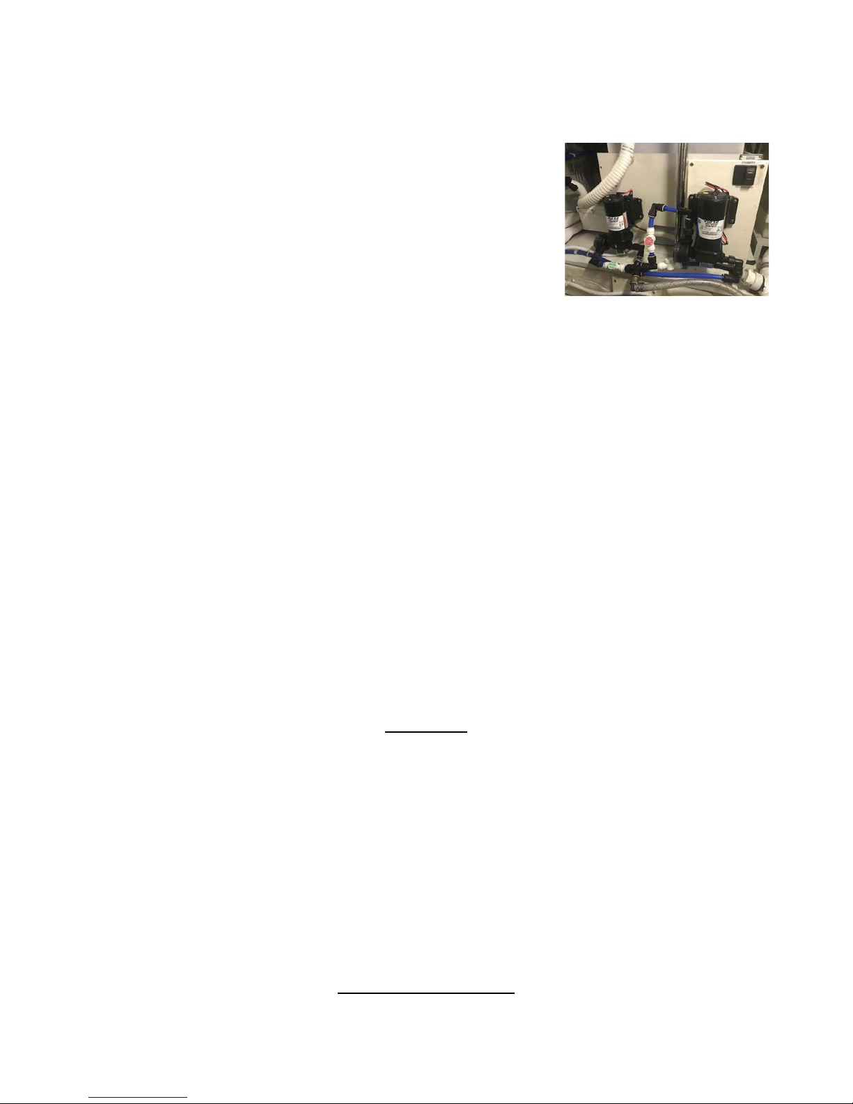
Page 11 of 15
might have an air lock and need to bleed the system by opening up a faucet. If you run out of water SHUT
OFF YOUR HOT WATER HEATER on the AC panel. Serious damage can occur!
A backup fresh water pump is installed just aft of the primary. In order to
switch to the backup pump:
1) Open the RED Valve
2) Close the GREEN Valve
3) Move the BLACK Electrical switch from PRIMARY to
SECONDARY
Hot Water Tank
The HOT WATER HEATER has an 20 gallon capacity tank and is available when connected to shore power,
using the generator, or via a heat exchanger underway. To use on shore power, flip on the water heater
circuit breaker on the AC electrical panel. Do not use the water heater if the water tank level is very low.
The water heater is located in the engine room, starboard side forward.
Shower
Before taking a SHOWER, make sure water pressure and shower sump breakers are on. Take only very short
“boat” showers (turning off water between soaping up and rinsing). To keep shower tidy wipe down the
shower stall and floor. Check for accumulation of hair in the shower and sink drains. An additional FRESH
WATER SHOWER is located on aft swim deck. Ensure that the faucets and nozzle are completely off after
use.
A pressured RAW WATER WASHDOWN is available from two hose spigots, one in the swim step locker
and one forward in the bow locker near the anchor windlass. To activate, flip the WASHDOWN PUMP
ROCKER SWITCH located in the 12 volt panel. After use, turn the switch off to prevent pump burn out, and
ensure no object leans on the switch to turn it on accidentally.
GALLEY
Stove/oven
The stove/oven is electric. Turn on the “stove” breaker on the AC panel. Clean stove top and oven after
each use. Do not use abrasive cleaners on the stove top. A soft scrub solution should be used.
Refrigerator
The REFRIGERATOR is dual voltage (12-volt and 110-volt power). It will automatically use 110-volt
power when the shore power is connected; otherwise, it will operate on 12-volt power. Monitor the use of
the refrigerator when the engines are not charging the 12-volt battery system. The local power switch is
located below the front door. It can be turned down to the lowest position when anchored or moored or
turned off when turning in for the night.
HEATING SYSTEM

Page 12 of 15
Built-in Cabin Heat (AC)
MAIN CABIN AND STATEROOM HEATERS keep each space at the desired individual temperature.
Controls are located in the main salon port side and in each stateroom. To make heat available you must be
on shore power or using the generator. Turn on all the AC power breakers on the main AC panel. Press
POWER on the left side of the thermostat in salon and staterooms, scroll through “Mode” options to HEAT,
set desired temperature and fan speed. There are three thermostats- Galley/dining room, master bedroom,
guest bedroom.
ELECTRONICS
Ohana’s Raymarine E120 System is an integrated navigational system. Both of the main instruments at the
lower helm provide radar, plotter, and gps in full screen mode or split screen, depending on your preferences.
They turn on by pressing the red “On” button and accepting the terms of use by pressing OK. You may
access the navigational mode you desire by scrolling through the options using the “Page” button on the
upper right hand corn of each instrument. You may find it helpful to dedicate one instrument to one mode
and the other to a different mode. For example, have one instrument set to plotter/gps and the other to radar.
Or, have one set to plotter/gps in large scale and the other to plotter/gps in small scale to see your local
position in detail as well as your destination. All electronics manuals are located in the salon cabinet
starboard side.
VHF Radio
There are two VHF RADIOS. The first is located in the lower helm to the right of the steering wheel.Make
sure the Electronics Main breaker is on located at the DC panel. There is a second VHF RADIO located at
left side of the upper helm. Turn on at upper helm. Volume controls are located on speakers near the VHF
controls. Always monitor channel 16 while underway.
Depth Sounders
There are two DEPTH SOUNDERS, one in the pilothouse and the other on the flying bridge. To activate the
DEPTH SOUNDERS, turn on Navigation Instruments on DC panel. Set the scale, shallow alarm, and deep
alarm as desired. The sounder should provide reliable readings in shallow waters. If in doubt, switch it off,
then turn it back on to reset sounder. If your reading is blinking, it is a FALSE reading. False readings can
occur in depths of more than 200 feet or in areas of strong currents or tides.
A second identical DEPTH SOUNDER is located at the upper helm.
Remember to ALWAYS consult your charts for depth!
Note -- GPS is considered a navigation aid. Do not rely on it. Compasses, charts, and dividers are the
tools to plot position, course, and speed. They are between the seat and window pane on the port side of
helm.

Page 13 of 15
ENTERTAINMENT SYSTEMS
AM/FM Stereo Radio
The Sony brand stereo unit is located on the forward starboard side of the salon It operates like a normal car
radio. There are Bose speakers (stereo) in the salon and two (stereo) on the bridge. The FADER controls
the distribution of the salon and bridge speakers. The BALANCE controls the sound distribution in the left
and right speakers.
CD Changer
The CD remote changer unit is located in the salon, and also master stateroom. The CD changer control
panel is left of the master stateroom bed. To activate the control panel, push the play button.
To remove the CD changer cartridge at the bottom of the cabinet, slide the cover to the right and push the
eject button.
TV/VCR
A TV/VCR is stored in the entertainment cabinet in the salon. To use, the remotes are marked with marking
tape for the unit they operate. The control to raise/lower the TV screen is located in the 2nd cabinet to the
right of the stove top. Push power button on Sony receiver on the top left. Raise TV with buttons inside port
galley cabinet by refrigerator. TV remote is in small box by lamp. DVD’s stereo is under receiver (no
satellite).
ANCHORING
The primary WORKING ANCHOR is a 60 lb. Delta and is attached to 300 ft chain passed through the deck
from the ANCHOR LOCKER. The locker can be accessed through the forward starboard deck hatch and a
side hatch within that locker.
The main breaker for the windlass is located in the engine room on the aft starboard bulkhead. It can remain
on and does not need to be touched unless it pops under heavy load. The WINDLASS POWER SWITCH is
located at the lower helm. Switch this on and go up on the bow to lower the anchor. At the bow remove the
restraining lanyard, tap gently on the ‘down’ foot control to lower the anchor. If necessary, gently guide the
anchor over the anchor roller to prevent binding on the pulpit.
Let out sufficient ANCHOR RODE (chain) before setting the anchor. Colored markers are placed every 50
feet on the chain, indicating the amount of rode. If the anchorage is crowded put down at least a 3 to 1 scope
(60 feet for 20 feet of water), back the anchor in with a short burst from the engine. Once the anchor sets,
slack out additional chain to a minimum of 4 to 1 scope. Let out additional scope dependent upon
conditions. Turn off WINDLASS SWITCH at lower helm.
Before raising the anchor, ALWAYS start the engines as it uses large amounts of power. Turn ‘on’ the
WINDLASS SWITCH and slowly maneuver the boat toward the anchor. As the boat moves toward the
anchor, press the ‘up’ control to take up slack line. Give the windlass short rests as you are pulling it up.
Place yourself in position to guide the anchor onto the roller. As the anchor rises, be careful not to allow it to
swing against the hull. Wash it down if you have a wash down pump before it goes into anchor locker.

Page 14 of 15
Reconnect the keeper between the anchor and windlass. Close the plastic covers on the FOOT PEDAL
CONTROLS. Turn ‘off’ the WINDLASS POWER SWITCH.
A SPARE ANCHOR is stowed in the engine room. The aft SPARE ANCHOR RODE is located in the
engine room. Attach the rode securely to the chain shackle.
Mooring Cans
Ohana is bigger than State rules allow for mooring to Washington Parks buoys.
BARBECUE
The BARBECUE is permanently mounted on the aft cockpit rail. Open the hatch on the swimstep locker to
access the propane tank. Attach hose to the barbecue, ignite, and bon appetite! Please wipe up any spillage
around the barbecue to prevent soiling the cockpit or swimstep. Shut propane off and disconnect hose after
use.
Ensure gasoline and flammable materials are not near the barbecue.
DINGHY & OUTBOARD MOTOR
Your Walker Bay 325 Supertender DINGHY with a 30hp Tohatsu 4 stroke engine is stored on the upper
deck aft. It has a capacity of about 950 pounds (motor, equipment, and 5 people). Please be careful as you
near shore so that the lower unit or propeller of the motor does not hit the bottom. You are better off
stopping and raising the motor early and paddling the last few yards to the beach.
Ohana has a high quality electric davit to raise and lower the dingy. To launch:
1) Plug the davit control into the receptacle on the davit base. The control is kept in the locker
under the front of the bridge chair.
2) Remove the dingy cover and store under seats in the upper deck salon.
3) Remove tie downs and store with cover.
4) Carefully slack the davit lift line down so the head knocker (line weight) can be detached from
the deck fitting. Swing the davit hook back to the boat and snap onto lifting harness ring.
5) With help from another person (or two) to steady it, lift the dingy and use the bowline and a stern
line to control the dingy as it is swung out over the side. Be particularly attentive to swells or
boat wakes during this process as they can cause the dingy to swing as it is launched. Using the
bow and stern lines to control the dingy is the best way to be safe.
6) Once the dingy is in the water, detach the lifting hook, be careful with the head knocker as you
raise the hook, and reattach it to the fitting in the deck, take the slack out of the lifting line.
To retrieve the dingy, reverse the above procedure. Be sure to reconnect the tie downs from dingy to
chocks.
Towing your dingy is a recipe for problems. Please load the dingy whenever you plan to travel.
When fueling the dingy remember the motor is a 4 stroke and uses straight gas. DO NOT USE GAS WITH
OIL IN IT. Whenever possible, purchase ethanol free gasoline for the dinghy engine.

Page 15 of 15
PFD'S: Coast Guard regulations state that any child 14 and under must wear a life jacket in a dinghy. It
is a good idea for EVERYONE to follow this rule. There are two stored in the cockpit locker, aft deck.
There are seven PFD'S stored in the cabinet on the bridge, on the starboard aft end. The flare gun and flares
are store here also.
CRABBING & FISHING
Always check the fishing and crabbing requirements before you leave on your cruise. You will need a
license. Many areas are CLOSED to crabbing and fishing on certain months.
CRAB AWAY FROM THE BOAT! Lines can get wrapped around props. Fish-flavored cat food, turkey
legs, or chicken backs are great bait. After 15-20 minutes, retrieve the crab line and ring quickly. Measure
the crabs using the CRAB MEASURING GAUGE inside the pocket of the crab trap cover. Keep the male
crabs of proper size (usually 6 ¼ inches across the carapace).Boil crabs about 15 minutes to cook.
Cleaning crabs before boiling saves space in the pot and makes for much cleaner move from pot to table.
Please cook all crab on the swim-step platform to avoid smelly boilovers.
There is a two gallon bottle of propane stored in the aft deck cabinet, accessed on the swim platform. Use it
for exterior BBQ and crab cooker. Please turn off the valve after each use.
After using, wash equipment thoroughly with fresh water (available from the cockpit shower faucet). Note --
Please do not store wet rings and gear inside the boat.
OTHER:Safety & Bilge Pumps
SAFETY should be paramount in your daily cruising. A MAN OVERBOARD DRILL should be discussed
and perhaps even practiced with a life jacket. Remember your lifejackets are stowed in the cabinet of the
lazerette in aft of boat. A few should always be out and ready. Your flares and safety equipment are located
on bridge, starboard aft cabinet.
Ohana is equipped with an AUTOMATIC BILGE PUMP. The master switch is located on the electrical
panel. Normally, the switch will be left in the AUTO position. Ohana has dripless shaft logs, so there should
not be any pump operation unless water enters from another source.
The ENGINE SPARES BOX (plastic blue color) is stowed to be stored in forward engine department This
includes oil filter, raw water impeller, pump parts, injectors, and other small parts.
THRU-HULL LOCATIONS
A thru hull fitting diagram is located in the owner’s manual in the starboard salon book shelf. The diagrams
are on p. 9.7.3 in the manual.
Table of contents
Popular Boat manuals by other brands


Jeanneau
Jeanneau SUN ODYSSEY 41 DS owner's manual

Meridian
Meridian 490 Pilothouse owner's manual

Advanced Elements
Advanced Elements AdvancedFrame Expedition AE1009 owner's manual

Robo Marine Indonesia
Robo Marine Indonesia GEOMAR user manual

Swallow Boats
Swallow Boats BayRaider owner's manual

X SHORE
X SHORE EELEX 8000 owner's manual


